Note: Descriptions are shown in the official language in which they were submitted.
CA 02469365 2004-05-28
MOISTURE DRAINAGE PRODUCT, WALL S3~'STEM INCORPORATING SUCH
PRODTJCT AND METHOD THEREFORE
Technical Field
[0001] This invention relates to moisture drainage products and, more,
particularly, to
moisture drainage products intended for incorporation in wall systems and
methods for
providing moisture drainage in wall systems.
background
[0002] Warm, moisture-laden air can exist in buildings even in buildings in
colder
climates. A significant amount of moisture can be placed into the air through
common
household activities, such as cooking, bathing and showering.
[0003] Especially in colder climates, insulation in a wall structure helps to
reduce
heat loss from buildings which are heated due to the cold climate. As moisture-
laden air
passes through the wall structure of such buildings, the moisture-laden air
encounters
steadily decreasing temperatures. As the air is cooled while moving from the
interior of a
wall structure to the exterior of the wall structure, the air can eventually
reach its dew
point and water vapor in the air condenses to form moisture. The result can be
a moisture
buildup in the wall structure.
[0004] Vapor barriers are commonly employed on the «-arm side of wall
structures in
order to prevent moisture-Laden air fram entering the wall structure. However,
vapor
barriers are not usually perfect. In a typical building, multiple penetrations
of a vapor
barrier can occur, e.g., from electrical and plumbing lines and from windows
and doors.
[0005] If the exterior temperature is cold enough, the moisture existing in
the wall
structure could eventually tum to frost or ice a.nd, thus, be prevented from
draining from
the wall structure, at least until the exterior temperature increases. When
that happens,
however, the moisture can still cause significant damage to the wall
structure.
[0006] Several products exist to allow drainage of moisture from wall
structures once
the riaoisture has formed in the wall structure.
[0007] U.S. Patent No. 3,654,765, Healy et al, Subterranean Wall Drain,
discloses a
subterranean wall drain unit including a drain pipe having openings therein
and a
longitudinally extending planar core defining channels normal to the pipe. A
water
pervious sheet material covers one face of the core and the openings in the
pipe to form a
-1-
CA 02469365 2004-05-28
filter therefore. The other face of the core may be covered with a plastic
sheet or other
vapor barrier.
[0008] U.S. Patent No. 3,888,087, Bergsland, Foundation Wall Protective Sheet,
discloses improvements in pratective membranes or sheets for foundation walls.
The
sheets have regular courses of protrusions for spacing the sheet from the
foundation wall
and a porous backing for drainage outwardly of the sheet. The protrusions
provide air
channels between the protective sheet and the foundation for thermal
insulation and for
facilitating drying of the foundation wall. Small vertical ribs between t'he
courses of the
protrusions provide convenient water passages to take care of drainage water
in the
porous backing without interfering with the air spaces and incidentally
providing bending
vertical lines for more facile installation handling. Modifications of i:he
sheet include
transverse ribs at lower portions of the sheet to allow horizontal bending
thereof wall for
footing and drainage configurations. A barrier for preventing back fill
falling between the
protective sheathing and foundation is also disclosed.
[0009] U.S. Patent No. 3,318,056, Thompson, Ventilating Wall Construction With
Stud Location Indicators, discloses a sheet of building material placed
between wall
veneers for moisture protection that includes vertical drainage channels and
perforations.
[0010] U.S. Patent No. 6,298,620, Hatzinilolas, Moisture Control Panel,
discloses a
moisture control panel used in exterior walls. A wall coazstructed with the
panel has an
inner back-up wall component and an outer wall component of a moisture
pervious
material, for example, stucco. The moisture control panel is positioned
between the two.
It has a base sheet on the iruzer face of the outer wall component. A set of
drying
perforations slope downwardly toward the inside through this sheet. This
drains moisture
from the inside of the outer wall component. On the inside, the bay sheet has
a set of
upwardly sloping bosses which provide an air space on the inside the moisture
control
panel providing for air circulation and drainage of any moisture.
[0011] U.S. Patent No. 4,381,630, Koester, Foundation Vent Structure,
discloses a
foundation vent structure positioned upon the footings of the building below
the
lowermost row of concrete blocks of the basement wall and extends bf;low the
concrete
floor of the basement. Tle vent structure is formed of a plastic material,
preferably in
strips, and is shaped to define alternate tunnels and channels having openings
therein.
The vent structure intercommunicates the openings in the hollow, concrete
blocks with
-2-
CA 02469365 2004-05-28
the drain area located along the marginal area below the basement wall to
permit moisture
to be vented into this drain area.
[0012] However, significant problems exist with such pre-existing products and
systems. Such products can prevent the continued movement of moisture of water
vapor
from the interior to the exterior side of the wall structure where the
moisture or water
vapor then exits the wall structure and, hence, can cause no further damage.
Such
products can also become contaminated with other construction materials being
used in
the formulation of the wall structure or otherwise in the construction of the
building.
Summary Of The Invention
[0013] The present invention helps prevent damage from moisture in a wall
structure
by draining such moisture from the wall structure using ridges and grooves to
form
vertical channels which allow such moisture to drain. The present invention
also allows
water vapor and moisture to pass through the product allowing such water vapor
or
moisture to continue its passage from the interior of the wall structure to
the exterior of
the building. And further, th~~ present invention prevents other consvtruction
materials
from contaminating the channels formed by the ridges and grooves permitting
moisture to
drain in the existing channels.
[0014] The present invention provides a .product adapted to allow drainage of
moisture from a wall of a structure. A sheet of corrugated material forms a
plurality of
ridges and grooves on opposite sides of the sheet of corrugated material. The
sheet of
corrugated material is relatively inflexible under a force applied generally
perpendicular
to the sheet. The sheet of corrugated material has a multiplicity of
perforations. A sheet
of water permeable material ins affixed to one side of the sheet of corrugated
material.
The product is flexible in a direction along the plurality of ridges and
grooves allowing
the product to be stocked in roll form.
[0015] In an alternative embodiment, the present invention also provides a
wall
system for a structure having an interior and an exterior. A plurality of
structural
members form a structural support for the wall system. Sheathing is placed
exterior of
the plurality of structural members. A moisture drainage product adapted to
allow
drainage of moisture from the wall s~rstem has a sheet o;f corrugated material
forming a
plurality of ridges and grooves on opposite sides of the sheet of corrugated
material. The
-3-
CA 02469365 2004-05-28
sheet of corrugated material is relatively inflexible under a force applied
generally
perpendicular to the sheet. The sheet of corrugated material has a
multiplicity of
perforations. A sheet of water permeable material is affixed to one side of
the sheet of
corrugated material. The product is flexible in a direction. along the
plurality of ridges
and grooves allowing the product to be stocked in roll form, The moisture
drainage
product is placed exterior of the sheathing with the ridges and grooves being
oriented in a
generally vertical direction with the sheet of water permeable material facing
the exterior.
An exterior veneer is placed exterior of the moisture drainage product.
[0016] In a preferred embodiment, the plurality of ridges and grooves are
parallel.
[OOI7] In a preferred embodiment, the corrugated material is a material
selected from
the group consisting of foils, such as copper, stainless sterol and aluminum,
plastics, and
cellulose materials with a moissure resistant additive.
[0018) In a preferred embodiment, the corrugated material is a material
selected from
the group consisting of cementuous and cementuous materials having a
reinforced scrim.
[0019] In a preferred embodiment, the plurality of ridges and grooves in the
sheet of
corrugated material are evenly spaced.
[0020] In a preferred embodiment, the sheet of water permeable material
comprises
polypropylene.
[0021] In a preferred embodiment, the polypropylene is a spunbond
polypropylene.
[0022) In a preferred embodiment, the sheet of water permeable material
comprises a
fabric.
[0023] In another alternative embodiment, the present invention provides a
method of
providing drainage of moisture from a wall of a structure, the wall having
structural
members and an exterior veneer. A moisture drainage product is applied to the
exterior of
the structural members. The rrloisture drainage product has a sheet of
corrugated material
forming a plurality of ridges and grooves on opposite sides of the sheet of
corrugated
material. The sheet of corrugated material is relatively inflexible under a
force applied
generally perpendicular to the sheet. The sheet of corrugated material has a
multiplicity
of perforations. A sheet of water permeable material is affixed to one side of
the sheet of
corrugated material. The product is flexible in a direction along the
Plurality of ridges
and grooves allowing the product to be stocked m roll form. The applying a
moisture
drainage product step is accomplished with the ridges and grooves of the sheet
of
corrugated material being oriented in a generally vertical direction with the
sheet of water
-4-
CA 02469365 2004-05-28
permeable material facing away from the structural members. l-1 veneer
exterior is
applied exterior of the moisture drainage product.
[0024] In a preferred embodiment, the veneer exterior is applied exterior to
the
moisture drainage product with the ridges and grooves of the sheet of
corrugated material
maintaining an ability to channel to channel moisture along the ridges and
grooves.
Brief Description Of The Drawing
[0025] Figure 1 is a plan view of a moisture drainage product constructed in
accordance with an embodiment of the present invention;
[0026] Figure 2 is a edge view of the moisture drainage product illustrated in
Figure
1;
[0027) Figure 3 is a close-up view a portion of the moisture drainage product
illustrated in Figure 1;
[002] Figure 4 is a partial cut-away perspective view of a wall structure
incorporating the moisture drainage product illustrated in Figure p;
[0029] Figure S is a perspective view showing the partial installation of the
moisture
drainage product illustrated in Figure f installed over sheathing in a wall
structure;
[0030] Figure 6 is a perspective view showing the partial installation of the
moisture
drainage product illustrated in Figure 1 in a wall structure with lathe
iinstalled over the
moisture drainage product; and
[003I] Figure 7 is a perspective view showing the partial installation of the
moisture
drainage product illustrated in :Figure 1 in a wall structure with stucco
installed over the
lather and the moisture drainage product.
Detailed Description
[0032] Since the presence of moisture in wall structures of buildings is not
uncommon, it is desirable to drain such moisture from the wall structure.
Figure 1 and
Figure 2 illustrate a section of moisture drainage product 10 constructed in
accordance
with an embodiment of the present invention. A sheet of corrugated material 12
is
formed from a sheet of plastic material which has been heated and passed
through a
crimping apparatus producing a series of linear ridges 14 and grooves 16
approximately
-5-
CA 02469365 2004-05-28
3/16 of an inch (0.48 centimeters) deep and approximately 7/16 of an inch
(l.ll
centimeters) on center.
[0033] In other embodiments, corrugated material 12 may be constt~ucted from
foils,
such as copper, stainless steel and aluminum, plastics, and cellulose
materials with a
moisture resistant additive.
[0034] As will be discussed with respect to later Figurc;s, linear ridges 14
and grooves
16 of corrugated material 12 form a plurality of channels which, when moisture
drainage
product 10 is installed in a wall structure with ridges 14 and grooves 16
oriented in a
generally vertical orientation, allows moisture which has accumulated in the
wall
I O structure to drain, via gravity, from the wall structure.
[0035] Corrugated material 12 also has a multiplicity o~f perforations 18
which may be
formed in corrugated material 12 either before. crimping or after although, in
a preferred
embodiment, perforations 18 are formed before crimping.
[0036] Perforations I8 in corrugated material 12 allow moisture, including
water and
I S water vapor, to pass through perforations 18. Perforations 18 allow water
vapor which
has not condensed in the wall structure to continue to pass outwardly through
the wall
structure. Further, perforations 18, since they are water pervious, allow
water moisture to
pass through corrugated material 12 and be drained from the wall structure
with the
channels formed by ridges 14 and grooves 16.
20 [0037] A sheet of material 20 is affixed to one side of corrugated material
12. As
shown in Figure 1 and Figure 2, sheet of material is affixed to the back side
of
corrugated material 12. The primary function of sheet of material 20 is to
prevent
building materials from accumulating in ridges 14 or grooves 16 on the side of
corrugated
material 12 having sheet of material 20. If buildia2g materials, i.n the
course of
25 construction, were allowed to accumulate in such ridges 14 and grooves L6,
the channels
formed by ridges 14 and grooves 16 could be obstructed by the building
material and the
drainage ability of the channels formed by ridges I4 anti grooves 16 could
obfuscated.
Sheet of material 20 is also pervious to moisture, including water and water
vapor.
[0038] In a preferred embodiment, sheet of material ZO is constructed of
30 polypropylene, preferably spunbond polypropylene. Alternatively, <,9heet of
material
could be constructed of a fabric woven of a moisture resistant material.
[0039] Sheet of material 20 may be affixed to corrugated material :l2 in any
suitable
manner such as by commonly available commercial construction adhesives.
-6-
CA 02469365 2004-05-28
[0040] Figure 3 is a close-up view of a portion of moisture drainage product
10
showing corrugated material I2 including ridges 14 and grooves 16 forming
channels,
perforations I8 and sheet of material 20.
[004I] Corrugated material I2 is constructed of a material which is rigid
enough such
j that, when comtgated with ridges 14 and grooves 16, is able to withstand
commonly
encountered construction forces as moisture drainage material 10 is being
installed in a
wall structure. Examples of commonly encountered construction forces are
hammer or
automated nailing strikes either affixing moisture drainage product 10 in the
wall
structure or affixing a later applied material in the wall structure such as
the exterior
veneer. As an example, an exterior veneer of stucco typically requires a lathe
material to
be applied exterior to moisture drainage product 10. The force required by
nails or spikes
to secure the lathe material to the wall structure should not compromise
ridges I4 and
grooves 16 to the extent that drainage channels formed by ridges I4 and
grooves 16 are
obstructed. Similarly, commoxily encountered forces involved in shipping,
storing and
I S handling of moisture drainage product I O should also not compromise the
drainage
channels. In a preferred embodiment, moisture drainage product IO is able to
withstand
the weight of a typical construction worker wearing shoes.
X0042] It will be appreciated that ridges I4 and grooves I6 of moisture
drainage
product 10 increase the rigidity of moisture drainage product as moisture
drainage
product 10 is attempted to be bent transverse to ridges 14 and grooves 1.6.
Thus, ridges
I4 and grooves I6 actually increase the rigidity of moisture drainage product
10 and help
allow moisture drainage product 10 to withstand normal construction forces. It
will also
be appreciated that ridges I4 .and grooves I6 in moisture drainage product 10
allow
moisture drainage product I0 t:o be less rigid in a direction parallel to
ridges I4 and
grooves 16. This relatively less rigidity allows moisture drainage product 10
to be
shipped, stocked and stored as a. roll stock. Preferably, moisture drainage
product IO can
be shipped and stored on ~0 foot (15.2 meter) rolls. Alternatively, moisture
drainage
product could also be shipped, stocked and stored as rigid sleet stock.
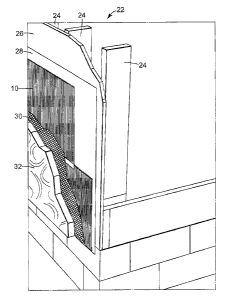
X0043] Figure 4 is an illustration of wall structure 22 c:.ontaining moisture
drainage
product 10. Starting at the interior side of wall structure 22, conventional
studs 24 form a
plane along which sheathing 26 may be affixed. Typically, and optionally, a
water barrier
2.8, such as #15 roll stock, is applied exterior to sheathing 26. l~toisture
drainage product
IO is affixed exterior to water barrier 28 with sheet of material 20 facing
outwardly.
_.
CA 02469365 2004-05-28
Sheet of material 20 extends beyond corrugated material I2 on one edge of the
roll of
moisture drainage product 10. This edge of sheet of material 20 is used to
overlap the
next roll of moisture drainage product I0. The lowest roll of moisture
drainage product
I0 in wall structure 22 has this edge of sheet of material 20 wrapped under
corrugated
material 12 to form a bug screen. A veneer for wall structure 22 is applied
exterior to
moisture drainage product I0. In one embodiment, the veneer consists
oj° a metal lathe 30
and stucco 32 applied over metal lathe 30. It is to be recognized and
understood that
many other forms of exterior veneer are also contemplated including, but not
limited to
concrete black, brick, natural or man-made stone, and wood siding of all types
including
IO wooden lap siding.
[0044] It can be recognized that without moisture drainage product IO in wall
structure 22 that moisture occurring or accumulating in wall structure 22 can
drain
through channels created by ridges 14 and grooves 16 :in moisture drainage
product.
Perforations 18 allow moisture drainage product L0 to be i~~ater pervious
allowing water
IS and water vapor to pass through moisture drainage product I0. This prevents
moisture
drainage product from a v apor Barrier in the middle of wall construction~~ 22
and actually
causing the moisture accumulation it is designed to ameliorate. Further, sheet
of material
20 prevents the stucco material 32 from obscuring channels formed in
corrugated material
I2 on the exterior side of moisture drainage product 10.
20 [0045] Figure 5, Figure 6 and Figure 7 illustrate a method of constructing
wall
structure 22.
[0046] In Figure 5, wall structure 22 is partially formed with studs :,4,
sheathing 26
and roll stock 28. This is a typical and conventional wall structure
construction
technique. Typically, studs 24 are installed and then sl2eathing 26 is affixed
to the
25 exterior side of studs 24. Roll stock 28 is then affixed to the exterior
side of sheathing 26.
Studs 24, sheathing 26 and, optionally, roll stock 28 form the structuraii
components of
wall structure 22. Of course, it is recognized and understood that wooden
studs 24,
sheathing 26 and rall stock 28 are just one example of what: could comprise
the structural
components of wall structure 22. Many other conventional, and unconventional,
30 products, materials and construction could also used. ~~s can Be seen in
Figure 5,
moisture drainage product IO is then conventionally affixed with construction
fasteners
exterior to roll stock 28 and sheathing 26. Note that sheet of material 20 is
again placed
on the exterior side of moisture drainage product 10. Thus, Figure 5 shows
wall structure
_g-
CA 02469365 2004-05-28
22 in a partially completed state with moisture drainage product 10 installed
but without
an exterior veneer.
[0047] In Figure 6, the canstruction of wall structure 22 has taken one more
step, the
step of partially completing the exterior veneer. In this ernbod_iment, th~~
exterior veneer
is stucco. In order to prepare wall structure 22 for stucco material 32,
lathe, preferably
metal lathe, 30 is conventionally affixed exterior of moisture drainage
product 10. In
Figure 7, stucco 32 can be seen having been applied to lathe 30. Again.,
especially since
stucco material 32 is semi-liquid when applied to lathe 30 and is intermixed
with lathe 30
to give stucco structural integrity, that it is likely that stucco 32 would
get into the
channels formed by ridges 14 and grooves 16 of corrugated material 12 if it
were not for
sheet of material 20 which effectively prevents the clogging of the channels
formed by
ridges 14 and grooves 16.
X0048] Various modi~catio:ns and alterations of this invention will be
apparent to
those skilled in the art without departing from the scope and spirit of this
invention. It
should be understood that this invention is not limited to the illustrative
embodiments set
forth above.
-9-