Note: Descriptions are shown in the official language in which they were submitted.
CA 02469441 2007-06-01
TITLE OF INVENTION
AN OPTICAL SENSOR USING A LONG PERIOD
GRATING SUITABLE FOR DYNAMIC INTERROGATION
Technical Field
This invention relates to an optical sensor, and more specifically to an
optical sensor
for monitoring dynamic events and associated interrogation methods.
Background Art
Optical sensors are well known in the art, and have utility in a number of
different
measurement applications. For example, and as shown in Figure 1, a fiber Bragg
grating 10
(FBG 10) formed in an optical fiber 12 or other optical waveguide can be used
to measure
pressure or temperature. A FBG, as is known, is a periodic or aperiodic
variation in the
effective refractive index of a core of an optical waveguide, similar to that
described in U.S.
Patents 4,725,110 and 4,807,950 entitled "Method For Impressing Gratings
Within Fiber
Optics," to Glenn et al. and U.S. Patent 5,388,173, entitled "Method And
Apparatus For
Forming Aperiodic Gratings In Optical Fibers," to Glenn.
FBG 10, when interrogated by broadband light from an optical source/detector
14,
will reflect a narrow band of this light (essentially a single wavelength),
called the Bragg
reflection wavelength, XB, in accordance with the equation XB a 2neffA, where
neff denotes the
index of refraction of the core of the waveguide, and A denotes the spacing of
the variations
in the refractive index of the core (i.e., the grating spacing). Because
strain along the axis of
an FBG affects its grating spacing A, and because temperature effects both the
index of
refraction neff and the grating spacing A (in the latter case, due to thermal
expansion or
contraction), FBG 10 can be used as either as pressure or temperature sensor
by assessing the
magnitude of the shift in its Bragg reflection wavelength. FBG 10 is usually
partially
transmissive so that a portion of the light at the Bragg reflection wavelength
(and light of all
other wavelengths that is not affected by the FBG 10) transmits through the
FBG 10, which
allows further sensors along the optical fiber 12 (not shown) to be
interrogated in a
multiplexing approach to determine the pressures and/or temperatures present
in those
locations.
2
CA 02469441 2007-06-01
When interrogating the FBG 10, the optical source/detector 14 can be operated
in a
continuous wave mode, where light is continuously fed to the FBG 10 and its
reflections are
continuously monitored, or the light can be pulsed. In a pulsed scheme, the
frequency of the
pulses needs to be sufficiently short to detect changes in the parameter being
measured. For
example, when measuring temperature in a given application, such as within an
oil/gas well,
it is noted that temperature does not change very rapidly, or at least it is
usually not of
interest to the well operator to detect such rapid changes if they occur.
Accordingly, light
pulses need to be sent from the optical source/detector 14 only occasionally,
for example,
every second, which provides an update of the temperature at the location of
FBG 10 every
second.
However, some parameters of interest to detect occur on much smaller time
scale. For
example, if the FBG 10 is used to measure a dynamic event, such as a pressure
wave
indicative of seismic activity occurring within the oil/gas well, sampling
needs to take place
more frequently. For example, a seismic pressure wave may contain frequency
components
as high as f=1000 Hz, and therefore would require interrogating the FBG 10 one
the order of
at least 2f times a second to properly resolve these higher order frequency
components and to
provide an accurate picture of the detected pressure wave. However, such high
frequency
rate pulsed sampling may not be possible in a practical application. For
example, the FBG 10
will likely in an oil/gas application be wavelength-division or time-division
multiplexed to
other optical sensors such as flow rate meters, speed of sound meters, or
other pressure or
temperature sensors, and such meters or sensors may themselves contain FBGs
which will
produce reflections. (Examples of such other meters or sensors, and ways of
multiplexing
and interrogating them, are disclosed in the following U.S. patents:
6,782,150, issued August
24, 2004; U.S. Patent 6,785,004, issued August 31, 2004; U.S. Patent
6,691,584, issued
February 17, 2004; U.S. Patent 6,354,147, issued March 12, 2002). High rate
sampling of
FBG 10 could interfere with interrogation of the other optical sensors or
meters multiplexed
with FBG 10, and/or confused the reflected signals, making it difficult to
determine which
reflections pertain to which meter or sensor.
3
CA 02469441 2004-06-02
As alluded to above, one solution to the problem of interrogating the FBG 10
to monitor
dynamic events is to interrogate the FBG 10 with a continuous wave light
source. Continuous
wave interrogation produces a continuous reflection of Bragg wavelengths
shifts from the FBG
10, which can be monitored as a function of time. However, continually
monitoring Bragg
wavelength shifts is difficult in many applications, and requires detectors
and signal processing
schemes that are not always economical in practice.
Accordingly, there is room for improvement in the art of optical sensors. The
art would
benefit from a sensor design which can monitor dynamic events in real time,
and which is
interrogatable using methods that are easily implemented and reliable.
Summary of the Invention
Disclosed herein is an optical sensor design and method for continually
interrogating that
sensor to produce an accurate representation of a dynamic event (such as a
change in strain,
pressure or temperature) being monitored by the sensor. The sensor design
preferably constitutes
continuous wave optical source/detection equipment coupled in series to a
first fiber Bragg
grating (FBG), a long period grating (LPG), and a second FBG formed in an
optical waveguide.
The LPG broadly attenuates light in the vicinity of the Bragg reflection
wavelength 12B of the
second FBG, and this attenuation profile shifts in wavelength in accordance
with the dynamic
event being monitored. Perturbation of the attenuation profile thus attenuates
the intensity of the
light reflected from the second FBG, i.e., I(42), because such reflected light
must pass (twice)
through the LPG. Accordingly, continually monitoring I(XB2) as a function of
time allows the
dynamic event to be recreated and processed accordingly. If necessary, I(XB2)
can be normalized
by dividing it by the intensity of the Bragg reflection wavelength from the
first FBG, I(XBi), to
discard attenuation within the system not related to the dynamic event being
monitored.
Brief Description of the Drawings
Figure 1 illustrates a prior art system for monitoring a parameter using an
FBG.
Figure 2A illustrates the disclosed interrogation system and sensor design
which
incorporates the use of a long period grating (LPG), and illustrates a dynamic
event to be
monitored by the system.
4
CA 02469441 2004-06-02
Figure 2B illustrates the reflection profiles of the FBGs which bind the LPG,
and also
shows the effect of attenuation through the LPG on the reflection profile from
the second FBG.
Figure 2C illustrates the detector output which constitutes a recreation of
the dynamic
event being monitored, as normalized to subtract out system parasitic
attenuation.
Detailed Description of the Preferred Embodiments
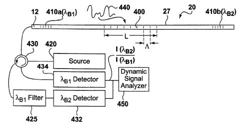
In Figure 2A, the parameter-measuring FBG 10 of Figure 1 has been replaced by
a long
period grating (LPG) 400 along the optical waveguide 12. The dynamic event 440
being sensed
effects the LPG 400, which acts as the sensitive element as will be explained
below. While
capable of detecting different types of dynamic events 440, such as
temperature variations, this
disclosure assumes for simplicity that the dynamic event 440 constitutes a
dynamic pressure,
such as a seismic pressure wave, which is the application for which the
improved sensor and
interrogation technique was primarily designed. The spacing A of the index of
refraction
modulation in an LPG 400 is greater than normally used in a narrow band Bragg
reflector,
ranging on an order of over 25 microns, e.g., about 100 microns, and
stretching over a length L
of approximately 2 cm. The LPG 400 provides coupling of light propagating in
the waveguide
to forward propagating cladding modes which are eventually lost due to
absorption and
scattering. The LPG 400 can be customized to couple light of specific
wavelength bands into the
cladding.
The LPG 400 is bounded by shorter reflective FBGs 410a and 410b having Bragg
reflection wavelengths XB1 and XB2 of, for example, 1530nm and 1550nm
respectively, and
having grating spacings A of 0.51 and 0.52 microns respectively. Because these
FBGs 410a,
410b are preferably not used in this embodiment as the pressure-sensitive
elements, but rather
are used merely to bind the pressure-sensitive LPG 400, FBGs 410a, 410b are
preferably isolated
from the pressures being sensed. Moreover, they can be remotely located from
LPG 400,
perhaps even by kilometers. Therefore, the FBGs 410a, 410b can be removed from
the
environment in which pressure sensing is taking place. For example, the FBGs
410a, 410b can
be located near the optical source/detection equipment residing at the surface
of an oil/gas well
(not shown), while the LPG 400 is deployed in the well to take pressure
measurements.
Alternatively, the FBGs 410a, 410b can be deployed in the environment to be
monitored, e.g., in
the well, but isolated from the pressures or temperatures in that environment
that might cause
5
CA 02469441 2004-06-02
their Bragg reflection wavelengths to significantly shift. For example, the
FBGs 410a, 410b
could be sealed in appropriate pressure vessels, or covered with high pressure
sheaths to prevent
their deformation. In any event, it is not strictly necessary to isolate the
FBGs 410a, 410b from
the pressures being measured, and they can in some applications also be
subject to the pressures
being measured as will be explained below. While Figure 2A shows the LPG 400
and the FBGs
410a, 410b as being formed along a common optical waveguide 12, this is not
strictly necessary,
and instead these components could be coupled or spliced together. For
simplicity, a grating is
said to be "formed in" an optical waveguide even if it is spliced or coupled
to a waveguide, and
two gratings are said to be "formed in" a single optical waveguide even if
they are located on
two waveguides which are coupled or spliced together.
In a preferred embodiment, continuous wave broadband light from light source
420
enters an optical circulator 430, which directs the light to the LPG 400 and
FBGs 410a, 410b.
As shown in Figure 2B, the LPG 400 imparts an insertion loss 423 to a
relatively broad spectrum
of light that passes through it, and this insertion loss profile 423
preferably overlaps the Bragg
reflection wavelength Xa2 of the second FBG 410b, more preferably near the
middle of one of
the broadly sloped edges of the profile 423 as shown. The dynamic pressure 440
being detected
changes the spacing of the index of refraction modulation for the LPG 400,
which causes every
point in the transmitted spectral profile 423 to shift in wavelength, as shown
at 424. It is
preferably to understand the exact shape of the insertion loss 423, and how it
responds to
pressure (424) prior to its inclusion in the system, which can be determined
by testing and/or
computerized modeling.
While light reflected from the first FBG 410a at XB1 is not attenuated by the
LPG 400,
light reflected from the second grating 410b at XB2 will be attenuated in its
intensity over region
426. (One skilled in the art will recognize that light at wavelength 42 is
attenuated twice,
because the incident light must pass to and from the second FBG 410b, and thus
will pass
through the long period grating twice; this multiplicative effect on the
attenuation in the reflected
intensity from FBG 410b is not shown in Figure 2B for simplicity). Because the
dynamics of the
insertion loss profile 423 and its response to pressure (424) are known, the
attenuation or change
of the intensity of light reflected from the second FBG 410b, i.e., I(XB2) can
be correlated to the
pressure presented to the LPG 400 at any given point in time.
6
CA 02469441 2005-06-02
This reflected light from the FBGs 410a, 410b then proceeds by way of
circulator 430 to
high frequency detectors 432 and 434. Detector 432 detects light tuned to the
Bragg ieflection
wavelength of the second FBG, X$2. Light tuned to 41, by contrast, is
reflected by filter 425 and
directed by circulator 430 to detector 434 where it is assessed. By comparing
the intensity of this
reflected signal I(42) at detector 432 with the intensity of the signal
reflected from the first
Bragg grating I(XBI) at detector 434, the dynamic strain 440 imparted to the
optical element 20
can be recreated in real time as shown in Figure 2C. Thereafter, the resulting
signal can be
assessed pursuant to well known signal analysis techniques; for example, the
signal's frequency
components can be assessed using a dynamic signal analyzer 450, which is well
known.
In this scheme, I(41) is used to normalize I(XB2), i.e., to remove attenuation
losses in the
system that are not due to dynamic pressure 440 impingent upon the LPG 400.
However, this is
not strictly necessary, and accordingly FBG 410a can be dispensed with, with
the variation in
I(71,H2) alone used to characterize the detected dynamic pressure. Dispensing
with normalization
in this fashion is particularly useful if the attenuation losses in the system
are well known or
characterized, or if the magnitude of the detected dynamic pressure 440 is not
interesting to
know with particularity. For example, in a seismology application, it may be
desirable to know
only the shape of the incident pressure wave, and hence it frequency
components, rather than the
magnitude of these components.
As noted earlier, this technique is beneficial in that it can operate with a
continuous wave
light source instead of by high rate pulsed sampling (although sampling can
also be used), which
allows detection of higher frequency components present in the dynamic strain
440. The
detectors 432 and 434 are accordingly preferably high frequency detectors
capable of resolving
the higher frequency components of interest in the dynamic pressure 440.
Either a broadband
light source 420, or at least a source containing frequency components tuned
to the two FBGs
410a, 410b, is suitable. One skilled in the art should note that separate
detectors 432 and 434
need not be used, and that a single detector capable of sensing both FBG
reflections can be used
instead. Moreover, the detectors 432, 434, source 420, circulator 430, and
signal analyzer 450
can be coupled together, e.g., in a common optical source/detection unit'(as
in 14 of Fig. 1),
although they are shown separately in Figure 2A to more easily understand
their individual
functions.
7
CA 02469441 2004-06-02
As noted earlier, the FBGs 410a, 410b are preferably isolated from the
parameter (in this
case, dynamic pressure 440) being sensed, although this is not strictly
necessary. Should FBGs
410a, 410b be subject to dynamic pressure 440, or other stresses in the
environment being
measured, such as temperature and pressure, the Bragg reflection wavelengths
X$1 and XB2 will
shift, but this is not deleterious and can be compensated for at the detectors
432, 434, and filter
425. For example, if it is known that the Bragg reflection wavelengths for
each of the FBGs
410a, 410b can be expected to vary +/- 5 nm in a given operational
environment, the detectors
432, 434, and filter 425 can be tuned accordingly to ensure that the detected
(or filtered) signals
correspond to FBGs 410a, 410b. For example, the XB2 detector 432 can be
designed to detect the
intensity of reflections occur within a band from 1545nm to 1555nm. If the
expected variation in
the Bragg wavelength shift of these FBGs is potentially greater, their Bragg
reflection
wavelengths can be set a further distance apart (e.g., 1520nm and 1560nm)
no,ensure no overlap
in detection of the bands of interest. In environments in which the FBGs are
subject to stresses,
it is particularly preferred to use normalizing FBG 410a to assist in
subtraction of intensity-
varying effects that are due to that environment, as opposed to the event in
that environment
being monitored.
The above-disclosed approach provides a simple way to recreate the detected
dynamic
pressure without the need for high rate pulsed sampling, and without the
inconvenience of
continuous wave spectral monitoring approaches used in the prior art. For
example, and as
discussed above, were a continuous wave source to interrogate the pressure-
sensitive FBG 10 in
Figure 1, the optical source/detector 14 would need to detennine the Bragg
wavelength shift and
track that shift as a function of time, a relatively demanding task. By
contrast, using the
disclosed sensor design incorporating the long period grating, the detector(s)
need only measure
intensity at one (or two) wavelengths (or at relatively narrow bands around
those wavelengths).
Intensity is easily determined by simply monitoring the detector current at
those tuned
wavelengths, and thus can be performed without the need to spectrally process
the reflected
signal.
Although FBGs 410a, 410b are preferred, it is not strictly necessary to use
FBGs to bind
the LPG 400. Any device, such as a tuned reflector, capable of reflecting
light at a given
wavelength (i.e., XBI and X$2) or in discrete bands can be used in lieu of
these components.
8
CA 02469441 2007-06-01
The disclosed sensor structure and method for interrogating the reflections
therefrom
can benefit and improve a wide variety of optical sensors, and particularly
those that are used
to measure dynamic events. An example of a sensor benefited by the disclosed
approach is
disclosed in U.S. Patent 6,955,085, issued October 18, 2005, entitled "Optical
Accelerometer
or Displacement Device Using A Flexure System". Other examples of sensors in
which the
disclosed technique can be employed include static strain or temperature
sensors, electrical
current sensors, chemical analysis sensors, vibration sensors, liquid level
sensors, etc. The
LPG can also be made sensitive to the external index of refraction which will
allow its use
for chemical and presence of liquids.
As disclosed in the above-referenced U.S. Patent 6,955,085, the LPG 400 can be
placed in the narrowed portion of a relatively large diameter "cane"
waveguide, with the
FBGs 410a, 410b, being placed at larger diameter portions of the cane
waveguide, in a so-
called "dog bone" structure. Alternatively, the LPG 400 (and or the FBGs 410a,
410b) can all
be placed in a large diameter cane based waveguide, without utilizing a
narrowed portion.
Further information concerning cane based waveguides can be found in U.S.
Patent No.
6,931,188, issued August 16, 2005.
If desirable, further loss can be imparted to the waveguide over and beyond
that
provided by the LPG 400. For example, the LPG could be replaced by notches in
the
waveguide, or air gaps, which would generally act to broadly attenuate light
passing
therethrough. Other techniques for purposefully imparting loss to the LPG, or
to optical
waveguide more generally, could also be used.
As used herein, "fiber Bragg grating" or "FBG" do not necessary imply that the
grating is contained within a fiber, i.e., a standard communications optical
fiber. Any suitable
grating for simplicity, and consistent with common nomenclature, is referred
to herein as an
"fiber Bragg grating" or "FBG" even if it is contained within larger diameter
waveguides
(e.g., cane-based waveguides) or other optical waveguides which are not
optical fibers, such
as those disclosed herein and preferably used in connection with the optical
sensing element
20.
"Long period grating" of "LPG" should not be understood to encompass gratings
having traditional grating spacings A for reflecting light near the visible
portion of the
electromagnetic
9
CA 02469441 2004-06-02
spectrum, e.g., from 400 to 800 nm. Instead, a "long period grating" or "LPG"
should be
understood as having grating spacings approximately at least 100 times large
than such typical
grating spacing values.
"Coupled" as used in this disclosure should not necessarily be interpreted to
require
direct contact. Thus, two elements can be said to be "coupled" from a
functional standpoint even
if an intennediary element intervenes between them.
"Light" as used herein does not necessarily constitute visible light, but
instead for
simplicity constitutes any portion of the electromagnetic spectrum useable to
interrogate the
disclosed sensors.
Although the disclosed sensors are described as being interrogated by
assessing reflection
therefrom, those of skill in the art will recognize that assessing
transmission of light through the
sensors is equally feasible.
Although designed as particularly useful for measuring seismic activity in.
oil/gas well
applications, the disclosed sensor and techniques can be used to sense dynamic
and constant
forces in any number of applications, including other industrial sensing
applications.