Note: Descriptions are shown in the official language in which they were submitted.
CA 02469617 2007-02-09
1
FLEXIBLE TRACK DRILLING MACHINE
FIELD OF THE INVENTION
The present invention relates to machines for drilling or performing other
work operations on large workpieces configured as simple- or compound-
contoured
panels or the like, such as wing and fuselage sections for aircraft. The
invention
relates more particularly to a flexible track machine and method for
positioning a
working module such as a drill, marking device, or the like, relative to a
workpiece by
traversing the module along a track mounted on and indexed to the workpiece.
BACKGROUND OF THE INVENTION
The problem of accurately drilling holes in large workpieces such as aircraft
wing and fuselage panels and other types of structures has been an ongoing
challenge
in the aircraft industry as well as other industries, and one for which a
completely
satisfactory solution applicable to a wide range of workpiece configurations
has not
heretofore been provided. Large fixed-monument machines such as five-axis
drilling
machines can be used for some types of workpieces, but these machines are
quite
expensive to procure and operate. In contrast, a relatively low-cost solution
to the
above-noted problem that has been developed by the assignee of the present
application and others is to mount an automated drill or other working module
on a
track that is mounted to the workpiece. The drill or module is supported on a
carriage
that travels along the track, which is formed by a pair of parallel rails
mounted on the
workpiece. For examples of such devices, see U.S. Patent No. 4,850,763,
assigned to
the assignee of the present application and U.S. Patent No. 3,575,364.
In the above-noted patents, however, the embodiments illustrated and
described were applied to workpieces that did not have compound-contoured
surfaces.
As used herein, the term "compound-contoured" is used to denote a surface
having
curvature in more than one direction. On such a compound-contoured surface, it
is
not possible in general to lay a pair of straight, flexible rails such that
the rails
conform to the surface contour and are the same distance apart at all points
along the
rails. Thus, the surface of a sphere is an example of a compound-contoured
surface,
because in the general case the spacing between a pair of flexible rails laid
on the
CA 02469617 2007-02-09
2
surface will vary. In contrast, a circular cylinder does not have a compound-
contoured surface, because the rails can be laid in either circumferential,
axial, or
helical directions and the spacing between them can be constant. In U.S.
Patent No.
3,575,364 noted above, a pair of flexible rails are mounted in the
circumferential
direction around a circular cylindrical workpiece. It will be appreciated that
the rails
can be perfectly parallel in such an arrangement, because the cylindrical
surface is a
simple-contoured surface. The rails in the '364 patent are made flexible so
that they
can be conformed to a variety of surfaces, but even such flexible rails cannot
be made
exactly the same distance apart at all points along the rails when they are
mounted on
a compound-contoured surface. Furthermore, rails mounted along two different
paths
on a compound-contoured surface will twist differently from each other because
of
the different directions of the surface normals along the two paths. This can
make it
difficult to traverse a carriage along the rails and maintain good accuracy of
carriage
positioning.
It is possible to mount a pair of spaced rails on a compound-contoured surface
such that the rails are the same distance apart at all points along the rails,
but only by
custom-designing the rails for the particular workpiece surface. If such
custom-
designed rails were used on a differently contoured surface, they would not be
the
same distance apart at all points. While it is highly desirable to be able to
traverse a
drill or other machine component on a pair of rails mounted on a compound-
contoured surface, it is also desirable to be able to use the same apparatus
on a wide
variety of surface contours, including simple- and compound-contoured
surfaces.
SUMMARY OF THE INVENTION
The above needs are addressed and other advantages may be achieved by the
present invention, which provides a flexible track machine for accurately
positioning
a drill or other machine component that can be used on simple- and compound-
contoured surfaces of various configurations. The machine has no rigid
monument or
foundation; rather, the workpiece itself supports the machine. More
particularly, a
pair of rails are mounted on the workpiece, and the drill or other machine
component
is traversed along the rails. The above-noted difficulties associated with
laying rails
on compound-contoured surfaces would seem to counsel making the rails flexible
in
CA 02469617 2007-02-09
3
all bending directions so that they act as splines, and fixing the location of
each rail at
a plurality of hard points spaced along the rail such that the rails are
precisely parallel.
The present invention, however does not take this approach.
In accordance with the present invention, a pair of spaced flexible rails are
mounted on the workpiece such that the rails extend along an X-axis direction
along
which the drill or other machine component is to be traversed. The rails are
placed
approximately parallel but, as noted, will not be precisely parallel when the
surface
has a compound curvature. An X-axis carriage is slidably mounted on the rails
and
supports the drill or other machine component. The X-axis carriage is driven
using
only one of the rails as a reference rail to set the X-axis location of the
carriage. The
other rail is not used as a reference but is used only to react forces on the
carriage in a
Z-axis direction (i.e., normal to the workpiece surface), such as from drill
thrust. The
rails are relatively stiff in bending about a first bending axis and
relatively flexible in
bending about a second bending axis orthogonal to the first bending axis. This
is
accomplished in preferred embodiments of the invention by configuring the
rails as
elongate plate-like structures having widths much greater than their
thickness. The
rails are mounted on the workpiece with the major surfaces of the plate-like
rails
substantially parallel to the workpiece surface, such that the first bending
axis is
substantially normal to the workpiece surface (parallel to the Z-axis) and the
second
bending axis is substantially parallel to the workpiece surface (parallel to
the Y-axis).
The rails thus are able to bend and twist to substantially follow the surface
normals of
the workpiece surface. In this manner, the rails are able to position the X-
axis
carriage so that it reflects the surface normal of the workpiece at any given
position
along the rails.
The machine component can be a drill, as noted above, but can also be other
types of devices, including but not limited to a marking device for applying
markings
on the workpiece, or a welding device. In any case, preferably the machine
component is mounted on the X-axis carriage via a Y-axis carriage that in turn
is
mounted on the X-axis carriage so as to be translatable along the Y axis
transverse to
the direction along which the X-axis carriage travels along the rails. Thus,
the
machine component is independently translatable in each of two axes.
CA 02469617 2007-02-09
4
The invention thereby enables the three-dimensional positioning of a drill or
the like relative to the workpiece to be accomplished by numerical programming
in
only two axes, i.e., the X- and Y-axes, since the rails and X-axis carriage
act to
automatically position the drill normal to the workpiece surface when the
drill is
suitably mounted on the X-axis carriage. In accordance with a preferred
embodiment
of the invention, a mathematical definition of the three-dimensional surface
of the
workpiece is transformed into a two-dimensional flat pattern, and numerical
programming of a controller for the X-axis and Y-axis carriage drive systems
is
performed in the two axes of the flat pattern. Thus, programming is
considerably
simplified compared with conventional multi-axis machines requiring
programming
in three or more axes.
The rails can be attached to the workpiece in various manners. In one
embodiment, a plurality of spaced attachment devices are mounted on the
workpiece
and the rails are releasably attached to the attachment devices. The
attachment
devices can attach to the workpiece by vacuum.
The X-axis carriage preferably is mounted on the rails by flexible mounts that
can accommodate varying bending and/or twisting that occurs along each rail
from
one end to the other when mounted on a compound-contoured surface. The
flexible
mounts can comprise plate-shaped springs affixed to the X-axis carriage and
having
rail-engaging rollers mounted thereon, or bearing cars coupled to the X-axis
carriage
by spherical bearings and having the rollers mounted thereon.
In the preferred embodiment, the flexible mounts comprise plate-shaped
springs that are rigidly affixed to the X-axis carriage near their middles
such that
opposite ends of each spring are supported in a cantilever fashion from the X-
axis
carriage. The rail-engaging rollers are mounted on the cantilevered ends of
the
springs. The springs preferably have a width that is smallest in the middle
and greater
at the ends so that the spring preferentially twists at the middle rather than
at the ends.
The X-axis drive device preferably employs a pinion gear mounted on one
cantilevered end of the plate-shaped spring that is disposed above one of the
rails (i.e.,
the reference rail). The pinion gear engages a rack mounted on the reference
rail. To
control the height of the pinion gear relative to the rack so that the height
is
substantially constant as the X-axis carriage is driven along the reference
rail, the
CA 02469617 2007-02-09
rotational axis of the pinion gear preferably lies in the same plane as the
rotational
axes of a pair of rollers mounted on the end of the spring. The rollers
preferably are
V-groove rollers that define V-shaped grooves in which the opposite edges of
the rail
are engaged, thus preventing movement of the rollers relative to the rail in
the
5 direction generally normal to the workpiece surface.
In a preferred embodiment of a flexible track drilling machine in accordance
with the invention, a pre-load force is applied between the X-axis carriage
and the
surface of the workpiece prior to drilling a hole, a normal component of the
pre-load
force having a greater magnitude than a normal component of reaction force on
the X-
axis carriage caused by thrust of the drill during drilling. This pre-load
force helps
stabilize the machine and takes up any play in the Z-direction that may exist
in the
connections between the attachment devices, rails, carriage, etc. Preferably,
the pre-
load force is applied by a pressure foot attached to the drill. The pressure
foot
preferably is connected with the drill such that the reaction force caused by
drill thrust
is reacted through the pressure foot so as to reduce the pre-load force
between the
pressure foot and the workpiece.
In summary therefore, in accordance with one aspect of the invention, there is
provided an apparatus for guiding and positioning a machine component relative
to a
surface of a workpiece. The apparatus includes first and second elongate
flexible rails,
the rails being spaced apart and approximately parallel to each other. The
apparatus
also includes a plurality of vacuum attachment devices connected to each rail
and
spaced at intervals therealong for releasably attaching each rail to the
surface of the
workpiece by vacuum, with the widths of the rails extending substantially
parallel to
the surface of the workpiece, the rails bending and twisting as needed to
substantially
follow the surface of the workpiece. The apparatus further includes an X-axis
carriage
structured and arranged to support the machine component, the X-axis carriage
slidably engaging the rails and being traversable along the rails so as to
position the
machine component relative to the workpiece.
Each rail may be relatively stiff in bending about a first bending axis and
relatively flexible in bending about a second bending axis orthogonal to the
first
bending axis, and each rail may be mounted on the workpiece such that the
first
CA 02469617 2007-02-09
5a
bending axis may be substantially normal to the workpiece surface and the
second
bending axis may be substantially parallel to the workpiece surface.
The apparatus may further include a connecting member connected between
the rails at a location therealong to substantially fix a spacing distance
between the
rails at the location, the rails having freedom to move toward and away from
each
other at other locations remote from the location.
The attachment devices may include vacuum cups.
The X-axis carriage may be connected to the rails by flexible mounts.
The flexible mounts may include plate-shaped springs.
The apparatus may further include an X-axis drive device for driving the X-
axis carriage along the rails, the X-axis drive device being mounted on one of
the
plate-shaped springs.
The X-axis drive device may include a drive member that engages a
cooperating member on one of the rails.
The drive member may extend through an aperture in the plate-shaped spring.
The X-axis carriage may be slidably connected to the rails by rotary members
that have a rolling engagement with the rails.
The rotary members may be mounted on flexible mounts that are affixed to the
X-axis carriage and can flex relative to the X-axis carriage to accommodate
varying
bending and twisting of the rails.
The apparatus may further include a drill mounted on the X-axis carriage.
The apparatus may further include an actuator connected to the X-axis
carriage and a pressure foot coupled with the actuator, the actuator being
operable to
press the pressure foot against the workpiece surface generally normal thereto
so as to
exert a pre-load force between the workpiece and the X-axis carriage.
The pressure foot may be connected with the drill such that a reaction force
caused by drill thrust during drilling of the workpiece may be reacted through
the
pressure foot so as to reduce the pre-load force between the pressure foot and
the
workpiece.
The drill may be mounted on a Y-axis carriage that may be slidable on the X-
axis carriage along a Y axis, and the actuator may be connected between the Y-
axis
carriage and the drill.
CA 02469617 2007-02-09
5b
The actuator may include a plurality of fluid-operated cylinders.
In accordance with another aspect of the invention, there is provided an
apparatus for drilling holes in a workpiece. The apparatus includes a pair of
rails each
of which is relatively flexible in bending about an axis extending in a
direction across
a width of each rail, and relatively stiff in bending about an axis extending
in a
thickness direction of each rail. The apparatus also includes a plurality of
attachment
devices attached to each rail at spaced locations therealong for attaching the
rails to a
surface of the workpiece such that the thickness direction of each rail is
substantially
normal to the surface of the workpiece. The apparatus further includes a
carriage
slidably mounted on the rails via a plurality of rail-engaging members
connected to
the carriage, the rail-engaging members being mounted on supports that are
attached
to the carriage, the supports and rail-engaging members being structured and
arranged
such that relative movement is permitted between the carriage and rails to
accommodate varying bending and twisting of the rails. The apparatus also
includes a
drill supported on the carriage.
The supports may include spring plates.
The rail-engaging members may include rollers.
The supports may include bearing cars that are attached to the carriage with
spherical bearings.
The rail-engaging members may include rollers.
The apparatus may further include a drive motor mounted on one of the
supports and in driving connection with a drive element that engages a
cooperative
driven element extending along one of the rails.
The drive element may be a rotary gear element and the driven element may be
a linear gear element, the supports being resilient and supporting pairs of
spaced
rollers that receive each of the rails therebetween, the rotary gear element
being
arranged such that a rotational axis thereof is coplanar with rotational axes
of one of
the pairs of rollers mounted on the support that supports the drive motor.
In accordance with another aspect of the invention, there is provided a method
of positioning a machine component relative to a compound-contoured surface of
a
workpiece such that a machine axis of the machine component is substantially
normal
to the surface of the workpiece. The method involves slidably mounting a first
CA 02469617 2007-02-09
5c
carriage on a pair of spaced-apart flexible rails that are relatively flexible
in bending
about first bending axes and relatively inflexible in bending about second
bending
axes. The method further involves affixing the rails to the surface of the
workpiece
such that first bending axes are substantially parallel to the workpiece
surface and the
second bending axes are substantially normal to the workpiece surface, whereby
the
rails bend and twist as needed to substantially conform to the surface of the
workpiece
such that a reference axis of the first carriage at any position along the
rails is
substantially normal to the workpiece surface. The method also involves fixing
the
machine component on the first carriage such that the machine axis of the
machine
component is aligned along the reference axis of the first carriage, whereby
the
machine axis is positioned substantially normal to the workpiece surface.
The method may involve providing a second carriage mounted on the first
carriage such that the second carriage may be slidable on the first carriage
along a
direction defined by a Y axis parallel to the workpiece surface, the first
carriage being
slidable along the rails in a direction defined by an X axis perpendicular to
the Y axis,
and wherein the machine component is affixed to the second carriage.
The method may involve determining a mathematical transformation of the
compound-contoured workpiece surface into a two-dimensional flat pattern, and
controlling positioning of the first and second carriages based on the flat
pattern.
In accordance with another aspect of the invention, there is provided a method
of positioning a drill for drilling a workpiece having a contoured surface
such that
drilling occurs along an axis that is substantially normal to the workpiece
surface at
any point thereon. The method involves transforming a mathematical three-
dimensional representation of the workpiece surface into a two-dimensional
flat
pattern such that each point (x, y, z) on the workpiece surface is transformed
into a
corresponding point (X, Y) on the flat pattern. The method also involves
positioning
the drill along the workpiece surface so that drilling will occur at a desired
point (xi,
yl, zr) by positioning the drill to intersect a point (XI, Y1) on the flat
pattern
corresponding to the point (xi, yi, zi). The method further involves orienting
the drill
with a drilling axis thereof substantially normal to the workpiece surface at
the point
(xj, yl, zi) by mounting the drill on a support system that is attached to the
workpiece
CA 02469617 2007-02-09
5d
surface and automatically orients the drilling axis substantially normal to
the
workpiece surface.
The step of orienting the drill may involve attaching a pair of spaced
flexible
rails to the workpiece surface such that the rails bend and twist as needed to
follow
the contour of the workpiece surface, with the rails approximately parallel to
each
other, and slidably mounting the drill on the rails, the rails positioning the
drill such
that the drilling axis is substantially normal to the workpiece surface at any
position of
the drill along the rails.
BRIEF DESCRIPTION OF THE DRAWINGS
The above and other objects, features, and advantages of the invention will
become more apparent from the following description of certain preferred
embodiments thereof, when taken in conjunction with the accompanying drawings
in
which:
FIG. 1 is a perspective view of a flexible track drilling machine in
accordance
with one preferred embodiment of the invention;
FIG. 2 is a perspective view of the machine with the drill spindle removed;
FIG. 3 is a perspective view similar to FIG. 2, but without the vacuum cups
and without the mounting elements for the drill spindle;
FIG. 4 is a perspective view showing the assembly of the X-axis carriage and
Y-axis carriage in engagement with the rails, generally from above;
FIG. 5 is a perspective view similar to FIG. 4, generally from below;
FIG. 6 is a cross-sectional view through the drill assembly of the machine;
and
FIG. 7 is a perspective view of an alternative embodiment of the invention.
DETAILED DESCRIPTION OF THE INVENTION
The present invention now will be described more fully hereinafter with
reference to the accompanying drawings, in which preferred embodiments of the
invention are
CA 02469617 2004-06-08
WO 03/049899 PCT/US02/35321
-6-
shown. This invention may, however, be embodied in many different forms and
should
not be construed as limited to the embodiments set forth herein; rather, these
embodiments are provided so that this disclosure will be thorough and
complete, and will
fully convey the scope of the invention to those skilled in the art. Lilce
numbers refer to
lilce elements throughout.
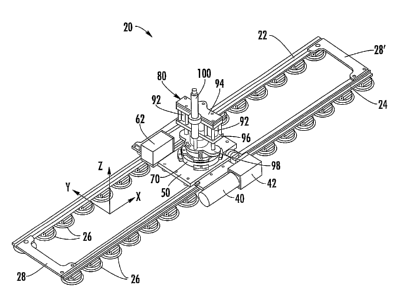
With reference to Figure 1, a machine 20 in accordance with one preferred
embodiment of the invention is shown. The machine comprises a pair of rails
22, 24 to
which a plurality of attachment devices, preferably in the form of vacuum cup
assemblies
26, are releasably affixed at spaced intervals along the length of each rail.
The rails 22,
24 preferably have a width substantially greater than their thickness such
that they are
substantially stiffer in bending about an axis that extends in the thickness
direction than
they are about an axis that extends in the width direction. The rails are
oriented
approximately parallel to each other, although the lateral spacing between the
rails can
vary when the rails are mounted on a compound-contoured workpiece surface.
Preferably, the rails are rigidly affixed to each other at only one end by a
connecting
member 28, which fixes the spacing between the rails at that end. At other
locations
along the rails, the spacing between the rails can vary as noted. There can be
another
connecting member 28' at the opposite end of the rails, but this connecting
member 28'
provides a "floating" connection that allows the spacing between the rails to
adjust as
needed depending on the contour of the workpiece surface.
The widths of the rails extend substantially parallel to the surface of the
workpiece when the vacuum cups are attached to the workpiece surface. Because
the
rails are able to easily bend about the widthwise directions and to twist
about their
longitudinal axes, the rails flex and twist as needed to substantially follow
the surface of
the workpiece and the vacuum cup assemblies maintain each rail at a
substantially
constant distance from the surface of the workpiece. In this manner, the major
surfaces
of the rails are substantially perpendicular to the surface normal of the
workpiece at any
point along each rail.
Mounted on the rails is an X-axis carriage 30 (FIGS. 2-5) that slides along
the
rails by virtue of rollers 32 that are mounted on the carriage 30 and engage
the rails. The
X-axis carriage 30 in the illustrated embodiment comprises a plate-shaped
member. The
rollers 32 are mounted along each of the opposite side edges of the carriage.
More
CA 02469617 2004-06-08
WO 03/049899 PCT/US02/35321
-7-
particularly, spring plates 34 and 36 (best seen in FIG. 5) are attached to
the carriage 30
adjacent to a lower surface thereof at each of the opposite side edges of the
carriage. The
spring plates are affixed to the X-axis carriage at locations 37 (FIG. 5)
spaced inwardly
from the opposite ends of the spring plates, such that each spring plate has
two opposite
end portions that are cantilevered from the carriage. The rollers 32 are
mounted on these
cantilevered end portions of the spring plates 34, 36. There are two opposing
rollers 32
mounted on each cantilevered end portion of each of the spring plates 34, 36.
Each rail
22, 24 is received between the opposing rollers 32. The rails 22, 24
preferably have V-
shaped edges engaged by the rollers, and the rollers are V-groove rollers
having V-
shaped grooves that receive the V-shaped edges of the rails. The rollers thus
prevent
relative movement between the rollers and rails in the direction along the
rotational axes
of the rollers, which axes are substantially normal to the workpiece surface.
The spring plates 34, 36 on which the rollers are mounted flex and twist as
needed (i.e., dictated by the contour of the workpiece surface as the X-axis
carriage
traverses the rails) to allow a limited degree of relative movement to occur
between the
X-axis carriage 30 and the rollers 32. This is facilitated by making the
spring plates
relatively narrow at their middles and wider at their ends, so that the plates
preferentially
bend and twist at the middle rather than at the ends where the rollers are
mounted. Thus,
a limited degree of relative movement can occur between the X-axis carriage
and the
rails 22, 24. The net result is that the flexible track machine 20 enables the
X-axis
carriage to traverse the rails along the X-axis (i.e., the axis parallel to
the length direction
of the rails) even though the rails may be bending and twisting in somewhat
different
ways relative to each other. In effect, the rails 22, 24 conform to the
contour of the
workpiece surface and thus approximate a normal to the surface at any point
along the
path defined by the rails. Consequently, a reference axis of the carriage (in
the illustrated
embodiment, an axis normal to the plane of the carriage) is maintained
substantially
normal to the worlcpiece surface at any position of the carriage along the
rails.
A rack 38 (FIGS. 2 and 3) for a rack and pinion arrangement is mounted along
the surface of the rai124 that faces the spring plate 36. A motor 40 and
associated
gearbox 42 are mounted on the spring plate 36. An output shaft from the
gearbox 42 has
a pinion gear 44 mounted thereon, and the spring plate 36 includes a window 46
(FIG. 4)
that the pinion gear extends through to engage the rack 38 on the rai124.
Thus, rotation
CA 02469617 2004-06-08
WO 03/049899 PCT/US02/35321
-8-
of the pinion gear 44 drives the X-axis carriage 30 along the rails. It will
be recognized
that the rail 24 having the rack 38 comprises a reference rail relative to
which the X-axis
positioning of the X-axis carriage is performed. No attempt is made to
determine or
control the X-axis positioning of the carriage relative to the other rai122.
It is important for accurate control of the X-axis position of the X-axis
carriage
that the pinion gear 44 have a constant height relative to the rack 38 at any
point along
the reference rai124. To accomplish this height control, the rotation axis of
the pinion
gear 44 preferably lies in the same plane as that defined by the rotational
axes of the two
rollers 32 mounted on the end of the spring plate 36. More particularly, the
axes of the
rollers 32 are parallel to each other and substantially norm.al to the
workpiece surface,
and the axis of the pinion gear 44 is substantially parallel to the workpiece
surface and
lies in the plane of the roller axes.
A Y-axis carriage 50 is slidably mounted atop the X-axis carriage 30 so that
the
Y-axis carriage can slide back and forth along a Y-axis direction
perpendicular to the X-
axis direction. More particularly, a pair of rails 52, 54 are affixed to the
opposite edges
of the X-axis carriage 30, and rollers 56 are mounted on the Y-axis carriage
for engaging
the rails 52, 54. A rack 58 for a rack and pinion arrangement is affixed to
the X-axis
carriage along the edge thereof adjacent to the rai154 (see FIG. 5). A motor
60 and
associated gearbox 62 are mounted on a plate 64 that is affixed to the Y-axis
carriage
adjacent to the rack 58. The plate 64 includes a window therethrough, and the
output
shaft of the gearbox 62 extends through the window and drives a pinion gear 66
that
engages the rack 58. Thus, rotation of the pinion gear 66 drives the Y-axis
carriage
along the rails 52, 54 in the Y-axis direction.
Mounted atop the Y-axis carriage is a clamp ring assembly 70, best seen in
FIG.
2. The clamp ring assembly supports and secures a drill assembly 80 as shown
in FIG. 1.
The drill assembly 80 includes a drill spindle 90. FIG. 6 depicts a portion of
the drill
assembly in cross-section, with the drill spindle 90 shown in a retracted
position on the
left-hand side of the figure and in an advanced position on the right-hand
side of the
figure. The drill spindle extends through a window in the Y-axis carriage 50
(visible in
FIGS. 3 and 4), and through a window in the X-axis carriage 30 (visible in
FIG. 5) that is
elongated in the Y-axis direction. The drill spindle is retracted and advanced
by a pair of
fluid cylinders 92 (FIG. 1) the cylinder portions of which are affixed to the
drill spindle.
CA 02469617 2004-06-08
WO 03/049899 PCT/US02/35321
-9-
More specifically, the cylinders 92 are connected between a pair of plate
members 94, 96
that are affixed to the spindle. The rods of the cylinders extend through
apertures in the
lower plate member 96 and attach to a plate member 98 that is affixed to the
clamp
assembly 70 on the Y-axis carriage. Thus, retraction of the rods into the
cylinder
portions causes the drill spindle to be advanced toward the workpiece, and
extension of
the rods causes the drill spindle to be retracted away from the workpiece. In
this manner,
a hole can be drilled in the worlcpiece with a rotary drill bit (not shown)
mounted in the
drill spindle. The axis of the drill along which the spindle is advanced and
retracted is
parallel to the reference axis of the X-axis carriage 50, i.e., normal to the
plane of the
carriage, and hence is substantially normal to the workpiece surface.
The machine also preferably includes a hydraulic check cylinder 100 shown in
FIG. 1, for controlling the speed of advancement of the drill spindle. The
check cylinder
is connected between the plate member 98 and the assembly of the plate members
94, 96
and fluid cylinders 92, and acts as a damping device to limit the advancement
speed of
the spindle.
With reference to FIG. 6, the drill assembly includes a pressure foot 102 that
is
extendable to bear against the workpiece suiface in a direction substantially
normal
thereto so as to exert a pre-load between the workpiece and the drill. A
piston 104
surrounds and is affixed to the body 106 of the drill. The piston 104 is
received into an
annular space defined in a cylinder 108 that surrounds and is affixed to the
clamp ring
assembly 70 on the Y-axis carriage. The pressure foot 102 is also affixed to
the body
106 of the drill. The piston 104 and cylinder 108 include seals as shown, such
that a
working chamber is defined in the piston-cylinder unit, which can be
pressurized via an
inlet port 110 to cause the piston 104 to be urged downward in FIG. 6, thus
urging the
drill downward and urging the pressure foot 102 against the workpiece surface.
The pre-
load exerted by the pressure foot against the workpiece preferably is of a
greater
magnitude than the maximum expected reaction force caused by the drill thrust
during
drilling of a hole. The drill thrust reaction force acts in a manner tending
to reduce the
pre-load between the pressure foot and the workpiece; stated differently, all
drill thrust is
reacted through the pressure foot. By pre-loading with a force greater than
the expected
maximum drill thrust, undesirable spindle movement can be minimized during
drilling.
CA 02469617 2004-06-08
WO 03/049899 PCT/US02/35321
-10-
An alternative embodiment of the invention is shown, in partial assembly, in
FIG.
7. This embodiment is similar to the previously described embodiment, except
that
instead of mounting the rollers 32 on spring plates 34, 36, the rollers 32 are
mounted on
bearing cars 37. Two bearing cars 37 are mounted to each of the opposite side
edges of
the X-axis carriage 30. Each bearing car 37 has two pairs of opposed rollers
32 that
receive the respective rai122 or 24 therebetween. The bearing cars 37 are
attached to the
X-axis carriage 30 by spherical bearings 39 that permit rotational movement of
the
bearing cars relative to the X-axis carriage. The bearing cars 37 and
spherical bearings
39 thereby provide the relative movement that the spring plates 34, 36 provide
in the
previous embodiment.
In accordance with the invention, the compound-contoured three-dimensional
surface of the workpiece is transfoimed or mapped to a planar or flat pattern
such that a
curvilinear distance between two points on the workpiece surface equates to a
linear
distance between corresponding points on the flat pattern. More specifically,
the three-
dimensional representation of the workpiece surface is transformed such that
each point
(x, y, z) on the workpiece surface is transformed into a corresponding point
(X, Y) on the
flat pattern. The drill is then positioned along the workpiece surface so that
drilling will
occur at a desired point (xi, yl, zi) by positioning the drill to intersect
the point (Xl, Yi)
on the flat pattern that corresponds to the point (xi, yl, zi). A numerical
controller for the
X-axis and Y-axis drive motors is programmed in the two-dimensional axis
system of the
flat pattern. The X and Y coordinates in the flat pattern generally correspond
to the X-
and Y-axes along which the carriages travel, but the correspondence in general
will not
be exact and a reference point is needed to calibrate the machine coordinates
to those of
the flat pattern.
To establish the relation between the flat pattern and the machine axes, two
locating holes are drilled into the workpiece at known locations, one at each
end of a
zone of the workpiece to be operated upon. The apparatus is attached to the
workpiece
such that a line connecting the two locating holes is approximately parallel
to the X-axis
defined by the rails and so that the locating holes are within the X-Y working
envelope
of the apparatus. The drill spindle is removed from the apparatus and a laser
edge finder
(not shown) is installed in its place. The X- and Y-axis drive motors are
operated to
position the carriages until the laser edge finder detects one of the locating
holes, and the
CA 02469617 2004-06-08
WO 03/049899 PCT/US02/35321
-11-
X and Y coordinates for the hole are stored in memory, and the process is
repeated for
the other locating hole. The coordinates of the locating holes in the frame of
reference of
the worlcpiece (as transformed into the flat pattern) are known. Thus, a
coordinate
transformation is performed to relate the machine X,Y coordinates to the
workpiece
coordinates in the flat pattern, so that the machine can be positioned at any
desired point
of the workpiece by controlling the X and Y drive motors to position the
machine at the
corresponding X,Y point.
Many modifications and other embodiments of the invention will come to mind
to one skilled in the art to which this invention pertains having the benefit
of the
teachings presented in the foregoing descriptions and the associated drawings.
For
example, while the rails 22, 24 in the illustrated embodiment achieve relative
flexibility
about one axis and relative stiffness about a perpendicular axis by virtue of
their widths
being much greater than their thicknesses, it will be recognized that there
are other ways
of achieving this characteristic. As an example, the rails could be made of a
material
having different moduli of elasticity in different directions, such as
composite materials,
or the cross-sectional shape of the rails could be designed to impart the
differential
flexibility. Furthermore, while rollers 32 are shown for engaging the rails,
other types of
members could be used instead of rollers for engaging the rails to facilitate
sliding of the
carriage 30 therealong, such as slide blocks or the like. Therefore, it is to
be understood
that the invention is not to be limited to the specific embodiments disclosed
and that
modifications and other embodiments are intended to be included within the
scope of the
appended claims. Although specific terms are employed herein, they are used in
a
generic and descriptive sense only and not for purposes of limitation.