Note: Descriptions are shown in the official language in which they were submitted.
CA 02469698 2004-06-03
- 1 -
POLE FOR RENdOTE OPERATION OF .A HAND TOOL
The field of the invention of this application is that
of the placement of fasteners of the nail or staple
type using a manually operated tool, but into a support
material remote from the operator a.nd inaccessible to
S his tool, even held at arm's length.
The support materiel mentioned here is, for example,
that of a ceiling.
The hand-operated tool mentioned here also is of the
kind of apparatus of the indirectly fired type for
driving fasteners, with a piston propelled forward
under the action of the combustion of a powder charge
or of the explosion of a. mixture of inflammable gases,
to drive a fastener.
The purpose of the invention is to avoid the operator
having to get up on a chair, a stool, or some other
form of stepladder, in order to be able to operate his
tool under good conditions of stability and of
attitude.
In the case of an indirectly fired apparatus, 'operate"
is to be understood as meaning operating the trigger of
the apparatus.
Thus, the invention relates to a pole for remote
operation of a hand tool comprising, at one end, tool-
securing means, a linkage for operating the tool, a
sleeve for operating the tool, designed to slide along
the pole, and means for securing the operating sleeve
to the linkage.
In the preferred embodiment of the pole of the
invention, the pole comprises at least one tubular
element in which the linkage runs and the operating
sleeve comprises a securing wedge that lies through a
window formed in the tubular element and through which
the linkage runs.
CA 02469698 2004-06-03
- 2 -
Also as a preference, the securing wedge is mounted to
pivot on the operating sleeve under the action of means
for returning this wedge to a wedging position on the
linkage.
Again as a preference, the pole of_ the invention is
telescopic and comprises at least two tubular elements
pushed one inside the other, the tool-securing means
being provided on the inner tubular element and the
operating sleeve on the outer tubular element.
In this case, sleeves for locking the relative position
of the two tubular elements may be provided.
It may then be beneficial for a first locking sleeve to
be secured on the outer tubular element at one of its
ends and to run along the inner tubular element to its
other end which is arranged in order', by screwing and a
wedging effect with a second sleeve arranged around the
inner tubular element to be clamped against the inner
tubular element and thus hold the two tubular elements
in position.
Advantageously too, the securing end of the operating
pole is tubular, a sheath to accommodate the linkage is
pushed into the tubular end of the pole from one end
and a tool-securing sleeve is pushed onto the tubular
end of the pole, the tubular end of the pole, the
sheath and the securing sleeve being secured together
so that they rotate as one.
Advantageously, the other end of the sheath is designed
to collaborate with a hub secured to braces for
standing the tool off in order, using a retaining yoke,
to create an antagonistic effect on the said tool and
thus immobilize the tool.
The invention will be better understood with the aid of
the following description of a preferred embodiment of
CA 02469698 2004-06-03
- 3 -
the remote operation pole according to the invention,
with reference to the attached drawing in which:
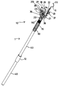
Figure 1 depicts a perspective view of the entirety
of the remote operation pole alone;
- Figure 2A is a view in longitudinal section of the
tool operating sleeve in the rest position;
- Figure 2B is a view in longitudinal section of the
operating sleeve while the tool is being operated;
- Figure 3 is a view in cross section of the operating
sleeve in the rest position;
- Figure 4 is a partial longitudinal sectional view of
the tubular elements of the pole of the invention
equipped with their locking sleeves;
- Figure 5 is a view in longitudinal section of the
tool-securing means;
- Figure 6 is a side view of the :securing end of the
operating pole and the tool secured to it, the
linkage being in the rest position; and
- Figure 7 is a perspective view of the same end and
the tool secured to it, in the operating position.
With reference to Figure 1, the remote operation pole
comprises a hollow cylindrical tubular element 40, a
linkage 11 running along inside the tubular element 40
and, at the end 10 of the pole l, means for securing
the tool 100 that is to be remotely operated (Figures 6
and 7). An operating sleeve 12, secured to the linkage
11 when the tool is operated remotely, slides along the
said tubular element 40 and allows the trigger 101 of
the tool 100 to be operated via the end 111 of the
linkage 11.
The tool-securing means are made up of a yoke in two
parts 21 and 25, pressing against a securing sleeve 20
secured to the end 10 of the pole, each part being
equipped with two claws 22, 23 and 26, 27 designed to
hold the tool under the antagonistic action of a thrust
standing it off from the end 10, exerted by stand-off
CA 02469698 2004-06-03
- 4 -
braces 36, 37, 38, 39 mounted on a hub 30 as explained
later on.
The operating sleeve 12, with reference to Figures 2A,
2B, 3, comprises a securing wedge 13 for securing it to
the linkage 11. The said wedge, of overall
parallelepipedal shape, is mounted to pivot about an
axle 19 provided in the sleeve 12. For this purpose,
the wedge lies through two windows 41, 42 formed in the
tubular element 40, these being more or less symmetric
with respect to the axis of the sleeve 12, of a length
more or less equal to the travel of the sleeve 12 on
the tube 40. The wedge is pierced with an orifice 18,
in this instance cylindrical, allowing the linkage 11
25 to pass with clearance. The clearance allows the wedge
to pivot, but through an angle 180 7.imited by its most
widely spaced opposed edges 181. Because the wedge lies
in two opposed windows of the tubular element 40, any
troublesome bracing effect when the pole length is
being adjusted is avoided.
A piston 14, pushed by a spring 15 bearing against a
ring 17 is pressed with some degree of firmness, or not
pressed at all, against the wedge 13, the ring 17 being
secured to the tubular element 40, in this instance by
means of a pin 16.
While in Figure 2A, the wedge 13 is not inclined by the
angle 180 and the linkage is therefore free to slide in
the orifice 18, in Figure 2B, the operating sleeve 12
can be urged manually downwards, compressing the spring
15, such that, under the action of the spring 15 and
the piston 14, the wedge 13 pivots and wedges the
linkage via the edges 181 of its orifice 18, thus
securing it to the sleeve 12. Conversely, the sleeve 12
is returned upwards by a device explained later on.
The remote operation pole is designed to be telescopic
and to comprise another tubular element 50, here an
CA 02469698 2004-06-03
- 5 -
inner one, sliding in the outer tubular element 40, and
able to be secured to it according to the desired
length of nesting.
As the ring 17 and the piston 14 leave a free passage
for the linkage 11, which linkage is designed to be
long enough, the linkage 11 can lae secured to the
operating sleeve 12 at a region of the said linkage
that corresponds to this length of nesting.
In order to adjust the desired length of nesting, with
reference to Figure 4, the outer tubular element 40
comprises a locking sleeve 60 secured to it at its end
furthest from the end 10 of the pole, by a pin 62, and
15, the inner tubular element 50 comprises a locking sleeve
70 mounted to slide along the tubular_ element 50.
The locking sleeves 60 and 70 collaborate to secure the
tubular elements 40 and 50 together at any region on
the tubular element 50, in the following way:
- the locking sleeve 70 comprises a tapped axial bore
72 that can be screwed onto a threaded external
cylindrical part 63 of the locking sleeve 60,
- the locking sleeve 70 comprises an axial tapered
bore 71 before the tapped bore 72 and the locking
sleeve 60 comprises, beyond its threaded external
cylindrical part 63, a split skirt 64 extending
along the inner tubular element 50 and ending in a
tapered surface designed to match the tapered bore
71 of the sleeve 70, having a certain elasticity and
thus affording a wedge effect,
- when the locking sleeve 70 is screwed onto the
locking sleeve 60 at the chosen point along the
tubular element 50, the securing tabs of the skirt
64, between the slits, are clamped onto the said
tubular element by the tapered bore 71 and this,
through a wedging effect, securer the inner tubular
element 50 to the locking sleeve 60 and therefore to
CA 02469698 2004-06-03
- 6 -
the outer tubular element 40 in a relative position
with respect to the latter.
Around the tubular element 50 a protective spring 90 is
inserted between the locking sleeve 70 and the securing
sleeve 20, so that as the tabs of the skirt 64 are
relaxed, the said sleeves do not come sharply into
contact with one another and risk injuring the user.
The means for securing the tool 100 to the end 10 of
the pole 1 will now be explained with reference to
Figures 5 and 6.
The securing sleeve 20 is secured to the upper end of
the inner tubular element 50, which is the end ZO of
the pole, and into which the end 81 of a sheath 80 to
accommodate the linkage 11 is pushed. The tubular end
of the pole (the inner tube 50), the sheath 80 and the
securing sleeve 20 are secured together by a pin 91.
The other end 82 of the sheath 80 has a thread onto
which the locking ring 31 of a hub 30 is screwed, the
tapping in the ring being a "left-hand" thread. The hub
is secured to stand-off braces, four of them in the
25 example considered here, numbered 36, 37, 38, 39,
uniformly arranged and having at their free end
cylindrical fingers 360, 370, 380, 390 designed to be
able to be pressed against surfaces 110 of the rear
structure of the tool 100.
30
In its central region, the sheath 80 comprises a fla nge
84 designed to collaborate with the securing sleeve 20
to hold a yoke comprising two parts, one male 25 and
one female 21, that are separable but designed to fit
together via male 29 and female 28 soles when they are
fitted between the flange 84 and the sleeve 20 on the
sheath 80.
CA 02469698 2004-06-03
_ '
When the tool 100 is in place in the yoke, the yoke
parts 21 and 25 extend beyond the rear structure of the
tool 100 as far as a shaping of the said structure that
has recessed surfaces 112 with the concave side facing
forwards, and against which claws 22, 23, 26, 27 of the
said yoke parts 21 and 25 can bear' and sit into the
recesses of these surfaces 112.
In addition, a finger 390 of the brace 39 passes
through a Iug 251 of the yoke part 25 (see Figures 1
and 5) so that when the yoke is turned about the pole,
the stand-off braces 36, 37, 38, 39 also turn about the
pole and drive the hub 30 in this ~:otation, which hub
then screws onto the sheath 80.
Likewise, the linkage 11 is driven in this rotation by
lugs 211 and 212 (see Figure 7) secured to the part 21
of the yoke. The result of this is that when clamping
the tool 100 between the yoke and the stand-off braces,
the tool, the parts 21 and 25 of the yoke, the stand-
off braces 36, 37P 38, 39, the hub 30 and the linkage
11 remain secured together so that they rotate as one.
Finally, the linkage 11 comprises a piston 9 sliding in
the end 82 of the sheath 80 and subj ected to a return
force exerted by a spring 83.
To fit the tool between the two parts 21 and 25 of the
yoke, they need to be parted from one another
transversely to the pole by causing their male 29 and
female 28 soles to slide one in the other, the rear
structure of the tool needs to be placed between their
claws 22, 23, 26, 27 then these two parts need to be
brought back together again in the :reverse movement in
order to bring their claws to face the surfaces 112.
To clamp the tool 100 between the claws of the yoke 22,
23, 26, 27 and the fingers 360, 370, 380, 390 of the
stand-off braces 36, 37, 38, 39, it is turned about the
CA 02469698 2004-06-03
pole 1 or the pole-securing sleeve 2C) is screwed around
the yoke and tool assembly. While this is being done,
as this assembly rotates as one with the hub 30, the
latter is screwed around the sheath 80. As the thread
on the sheath and on the ring 31 is a left-hand thread,
the fingers 360, 370, 380, 390 move away from the end
of the pole, and then, by pressing against the
surfaces 110 of the rear structure of the tool 100,
cause the tool itself to stand off from the pole, and
10 press the surfaces 112 against the claws 22, 23, 26, 27
of the yoke. By an antagonistic effect due to the yoke,
the soles 28, 29 exert a pulling action on the flange
84 of the sheath 80, and this secures them to the sheath
80, and therefore to the end 10 of the pole 1.
To operate the tool, the operating sleeve 12 is pulled
downwards (if the tool has to be offered up upwards),
and this compresses the spring 15 via the piston 14.
The piston 15 pushes back and causes the pivoting of
the wedge 13 into a securing position (181) securing
the linkage 21. Thereafter, the linkage is pulled
downwards and operates the trigger 101 of the tool via
an end nib 111. At the same time, via the piston 9, the
linkage 11 compresses the spring 83.
Once the tool has been operated, the operating sleeve
12 is released, the spring 83 pushes back the piston 9,
and this has the effect of pulling the linkage 11
upwards (still assuming that the tool is being offered
upwards) , moving the end nib 111 avaay from the trigger
101 and detaching the said linkage from the operating
sleeve 12 which, under the action of the spring 15, of
the piston 14 and of the wedge 13, returns to its rest
position, that is to say the position it had prior to
operation.