Note: Descriptions are shown in the official language in which they were submitted.
CA 02469711 2004-06-07
WO 02/46571 PCT/US01/48312
WELLBORE FLUID RECOVERY SYSTEM AND METHOD
BACKGROUND OF THE INVENTION
1. Field of the Invention
The present invention relates generally to drilling and completion fluid
recovery and,
more specifically, to a system for preventing wellbore fluids from being
spilled when the
threaded connections between the joints of the wellbore tubulars are
disconnected, while
being tripped out of the wellbore.
2. Description of the Background
During what is sometimes called a "wet" trip, a release of drilling fluid may
occur
with each of a large number of drill pipe connections that are broken. As the
drill pipe string
is being removed from the well, for example to substitute a new drilling bit
for a worn
drilling bit, the drilling mud that may remain in the string can create
considerable problems.
Each stand of drill pipe maybe approximately ninety feet long in accordance
with the drilling
rig size. Depending on well conditions, the pipe which is removed may
therefore contain up
to a ninety-foot column of drilling fluid therein. Although variable based on
the size of the
2 o drill pipe, the volume of fluid in a ninety-foot column may be in the
range of as much as one
hundred fifty gallons. When a threaded joint between the stand of drill pipe
and the drill
string is disconnected, this column of mud is released to flow from the length
of the drill
pipe. This release of wellbore fluids may typically occur many times during a
"wet" trip.
Drilling and completion fluids which include fluids such as weighted n1ud, oil-
based
CA 02469711 2009-04-16
fluids, water-based muds and the like are often quite expensive and may
frequently cost more
than one million dollars per well. Loss of such fluids during the numerous
pipe trips made per
well can therefore be quite costly as the fluids will need to be replaced.
Moreover, the loss of
such fluids can also create pollution which is highly undesirable. As well,
the fluids may
create an unusually slippery rig floor and surroundings so as to cause safety
problems by
increasing the likelihood of accidents to operators working on the rig floor.
The above problems are well known in the oil industry and therefore many
efforts
have been made in past years to limit spillage. One exemplary prior art system
for a drilling
mud container apparatus is disclosed in U.S. Patent No. 5,295,536, issued
March 22, 1994, to
Robert E. Bode. The drilling mud container apparatus provides a container for
preventing
spilling of drilling mud onto the rig floor to thereby save the mud for later
reuse. The
invention includes a diametrically split and hinged barrel having a fixed
lower seal assembly
and a movable upper seal assembly which engage the outer wall of the drill
pipe respectively
below and above a joint connection that is to be unthreaded. Upon
disconnection of the joint
and upward movement of the drill pipe, the upper seal moves upward with the
pipe to
eliminate wear which otherwise would result in seal and mud leakage. The
container includes
a large drain port and is adapted to be connected to a suitable hose which
leads to a mud pit or
tank.
However, several significant problems still exist with prior art fluid
recovery systems.
One problem relates to the amount of time required for the recovery system to
operate.
Draining large amounts of fluid as each connection is broken considerably
increases the
overall effective time required to break each connection and therefore
significantly increases
the time required for tripping the drilling string out of the wellbore.
Therefore, the associated
time costs of wet trips may also significantly increase the cost of drilling
the well.
2
CA 02469711 2004-06-07
WO 02/46571 PCT/US01/48312
As another factor, unless considerable time is allowed for drainage and
dripping, depending
on the viscosities and flow rates of the fluid, size and length of pipes,
drilling fluid losses
may still occur that are greater than permissible under governmental
regulations even though
the losses are greatly reduced. Another problem is related to the size of the
container that
must be secured around the pipe joint. To avoid the need for numerous
different size
containers related to the expected volume of fluid and size of pipe, a single
container size
with removable seals designed for each pipe size is generally constructed to
be large enough
in volume to handle the largest flows anticipated. However, due to this large
size, the
container can be awkward to work with thereby resulting in more loss of time
as well as the
inconvenience and hazards of working with unwieldy and bulky equipment.
Consequently, it would be desirable to further improve prior art drilling and
completion fluid recovery prior art systems. It would be highly desirable to
reduce loss of
drilling fluid even more than has been possible in the past, and to do so in
much less time.
It would also be desirable to reduce the size of the container used in prior
art systems while
still retaining the ability to handle the maximum possible fluid flow as the
pipe connection
is broken. Thus, it would be desirable to save the considerable cost due to
time loss while
even further reducing any loss of expensive and possibly environmentally harmf-
ul drilling
fluids. It is always desirable to further improve safety conditions. Those
skilled in the art
have therefore long sought and will greatly appreciate the present invention
which addresses
these and other problems.
3
CA 02469711 2004-06-07
WO 02/46571 PCT/US01/48312
SUMMARY OF THE 1NVENTION
The present invention was designed to provide more efficient operation to
thereby
save time and reduce drilling costs, significantly improve speed of breaking
pipe joints
during a wet trip, permit increased automation to reduce required manpower,
improve safety,
and to reduce any possible well fluid loss into the environment.
Therefore, it is an object of the present invention to provide an improved
wellbore
fluid recovery system.
Another object of the present invention is to have the ability to reduce the
time
required for breaking joints during a wet trip.
Yet another object of the present invention is to reduce the size of the
container
positioned around the pipe joint to catch fluid when the joint is broken.
An advantage of the present invention is improved rig safety.
Another advantage of the present invention is faster operation.
Yet another advantage is lower costs.
These and other objects, features, and advantages of the present invention
will
become apparent from the drawings, the descriptions given herein, and the
appended claims.
Therefore, the present invention provides for a wellbore fluid recovery system
for
recovering wellbore fluid when breaking one or more j oints of wellbore
tubulars comprising
elements such as a container mountable around each of the one or more joints
of the wellbore
tubulars, a receiving tank, a first conduit between the container and the
receiving tank, and
a vacuum source operable for producing a vacuum within the receiving tank.
A first valve may preferably be provided for controlling flow through the
first
conduit. A vacuum tank is included in a preferred embodiment of the invention
and the
4
CA 02469711 2004-06-07
WO 02/46571 PCT/US01/48312
vacuum source may be adapted for producing a vacuum in the vacuum tank. A
second
conduit between the vacuum tank and the receiving tank is preferably provided
with a second
valve for controlling flow through the second conduit. A wellbore fluid
storage tank, such
as a trip tank, is connected to the receiving tank by a third conduit. A third
valve controls
flow through the third conduit.
In one preferred embodiment, the container for attachment around the pipe
joint has
a container volume less than a volume of the colunm of wellbore fluid to
thereby provide a
more compact container.
The method of the invention may preferably comprise steps such as the steps of
placing the container around the joint, unscrewing the joint, applying the
vacuum to the
container, and collecting the fluid in the receiving tank. The step of
applying the vacuum
may further coinprise opening the first valve to permit fluid communication
between the
receiving tank and the container. Prior to opening the first valve, the vacuum
is preferably
produced in the receiving tank. In a preferred embodiment, the vacuum is first
produced in
the vacuum tank and then the second valve between the vacuum tank and the
receiving tank
is opened. Prior to operation, all three valves are closed. After fluid is
collected in the
receiving tank, the third valve is opened to drain the wellbore fluid into a
storage tank.
BRIEF DESCRIPTION OF THE DRAWINGS
FIG. 1 is a schematic view of a system in accord with an embodiment of the
present
invention prior to breaking of the wellbore tubular joint;
FIG. 2 is a schematic view of the system of FIG. 1, when the wellbore tubular
joint
5
CA 02469711 2009-04-16
is broken and fluid is drawn by vacuum into a receiving tank in accord with an
embodiment
of the present invention;
FIG. 3 is a schematic view of the system of FIG. 2, after fluid has been drawn
into the
receiving tank and flows therefrom by gravity into a rig site well fluid
reservoir as the drill
pipe is racked in the derrick; and
FIG. 4 is a schematic view of the system of FIG 3, after fluid has flowed out
of the
receiving tank and a vacuum is again produced in the receiving tank to place
thereby the
system in the status shown in FIG. 1.
While the present invention will be described in connection with presently
preferred
embodiments, it will be understood that it is not intended to limit the
invention to those
embodiments. On the contrary, it is intended to cover all alternatives,
modifications, and
equivalents included within the spirit of the invention.
DETAILED DESCRIPTION OF THE PREFERRED EMBODIMENTS
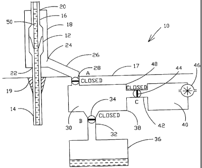
Referring now to the drawings which show operation of fluid recovery system 10
in
accord with the present invention, and more particularly to FIG. 1, there is
shown drilling
recovery system 10 prepared for receiving wellbore fluids such as drilling or
completion
fluids as wellbore tubular threaded connection 12 is broken apart in a manner
known by those
skilled in the art. Thus, wellbore pipe string 14, such as a drill pipe
string, completion string,
production string, or other wellbore tubular string, is being pulled from the
wellbore through
rig floor 17. Upper stand of pipe 16 may typically include about three drill
pipes threadably
connected together. Each drill pipe is typically about thirty feet long. The
drilling rig height
6
CA 02469711 2004-06-07
WO 02/46571 PCT/US01/48312
normally allows multiple pipes to be contained in each stand so that, for
instance, only every
third pipe connection needs to be disconnected. Each stand is lifted, set
aside, and stacked
upright on one side of the derrick until drill pipe string 14 is to be run
back into the well. By
working with stands of multiple pipes rather than individual pipes, a great
deal of time is
saved.
Depending on the hydraulics of the wellbore, it may be that the annular
pressure
outside the drill string 14 is greater than the pressure within the drill
string. This may occur,
for instance, due to heavy cuttings in the wellbore fluid, U-tube effects, and
the like. When
pulling out the drill string with a bit having small or clogged j ets,
nozzles, or water ways, the
mud maybe trapped in the drill string or not have time to drain during the
trip out of the hole.
Thus, it is well known that when connection 12 is broken, approximately ninety
feet of mud
column inside drill stand 16 may be dumped out of the bottom end of stand 16.
Prior to
breaking connection 12, slips 19 engage drill string 14 to prevent drill
string 14 from
dropping into the wellbore when connection 12 is released. The connection may
then be
initially slightly rotated a few degrees by applying a high initial breaking
torque with
powered tongs of which there are many types. Prior to spinning stand 16 with
respect to
wellbore string 14 to thereby completely unscrew connection 12, and perhaps
prior to initial
breaking of the connection with power tongs as discussed above, fluid recovery
container 18
is preferably placed around connection 12 in a manner known to those of skill
in the art.
2 o Fluid recovery container 18 will preferably include upper and lower seals
such as upper seal
above joint 12 and lower sea122 below joint 12. The seals maybe of various
types such
as sliding seals and the like as are known in the prior art.
It will be understood that such terms as "up," "down," "vertical" and the like
are
made with reference to the drawiings and/or the earth and that the devices may
not be
7
CA 02469711 2004-06-07
WO 02/46571 PCT/US01/48312
arranged in such positions at all times depending on variations in operation,
transportation,
and the like. As well, the drawings are intended to describe the concepts of
the invention so
that the presently preferred embodiments of the invention will be plainly
disclosed to one
of skill in the art but are not intended to be manufacturing level drawings or
renditions of
final products and may include simplified conceptual views as desired for
easier and quicker
understanding or explanation of the invention. As well, the relative size of
the components
maybe greatly different from that shown, e.g., a wellbore fluid storage tank
such as trip tank
36, discussed below, may typically be much larger than receiving tank 30.
Outlet 24 is provided from container 18, and is connected by hose or pipe 26,
through
valve 28 to recovery tank 30. Valve 28 may be of many types including but not
limited to
rotatable element valves such as ball valves, plug valves, butterfly valves,
and the like,
sliding element valves such as gate valves and the like, pivotal element
valves such as
flapper valves, plunger and seat valves, and any other suitable valves. Thus,
valve 28 may
be any type of valve so long as it is suitable to provide the function of the
system as discussed
hereinafter. Valve 28 may be manual or automatic, hydraulically operated, air
operated,
biased to one position as desired, or have other controls and the like. Again,
any variety or
combination of operating features may be used for controlling valve 28 so long
as such
operational features are suitable to provide the function of the system as
discussed herein.
As well, valve 28 may comprise more than one valve, more than one valve
element, single
or multiple valve controllers or actuators and the like, and/or more than one
conduit such as
conduit 26.
Recovery tank 30 has one or more outlets such as outlet 32 with one or more
valves
such as valve 34 that leads to rig reservoir tank 36- for storing welibore
fluids such as a trip
tank, mud pit or tank, and/or other fluid tank in which it is desirable to
store the recovered
8
CA 02469711 2004-06-07
WO 02/46571 PCT/US01/48312
wellbore fluids. Outlet 32 may preferably be located on or near bottom section
38 of fluid
recovery tank 30 so as to facilitate gravity feed or flow of fluid from
recovery tank 30 to
reservoir tank 36. Valve 34 could also be of many types and could be operated
by many
methods and controls some but not all of which were mentioned above in
connection with
valve 28. Valve 34 may or may not be the same type of valve or valves as valve
28.
Recovery tank 30 also connects to vacuum tank 40 through one or more outlets
such
as outlet 42 through which fluid flow is controlled by one or more valves such
as valve 44.
Valve 44, like valves 34 and 28 discussed above may be of many different types
with many
different types of controls. Vacuum tank 40 includes, in a presently preferred
embodiment,
one or more vacuum pumps such as vacuum pump 46 for producing a vacuum within
vacuum tank 40. Outlet 42 may preferably be located near an upper or top
section 48 of
reservoir tank 30 to reduce the likelihood of liquid flow therethrough.
In the sequence of operation of a preferred embodiment of the invention as
illustrated
by FIG. 1, valves 28, 34, and 44 are initially closed. A vacuum has been
formed in receiving
tank 30, as will be discussed subsequently. Because all outlets 26, 32, and 42
are closed by
their respective valves 28, 34, and 44, the vacuum is maintained within
receiving tank 30.
Receiving tank 30 is therefore sufficiently air tight for this purpose.
Receiving tank 30 has
sufficient volume to receive the entire column 50 of wellbore fluid in stand
16 and so may
preferably be greater than one hundred fifty gallons or any suitable size for
quick filling
thereof.
In FIG. 2, stand 16 has been rotated such as with a spinner, or other pipe
rotating
means which may be of many different types typically but perhaps not always in
the
counterclockwise direction indicated by arrow 52 to thereby unscrew joint 12
to break apart
pin 54 from box member 56. Therefore wellbore fluid in column 50 flows out
into container
9
CA 02469711 2004-06-07
WO 02/46571 PCT/US01/48312
18 which, as stated above, is preferably sealed around pipe or stand 16 with
seals such as seal
20 and 22. Use of the present invention reduces the likelihood of leakage of
seals 20 and 22
due to the vacuum applied to container 18 as discussed herein. During this
time period, or
shortly before or after the stand is spun to discoimect j oint 12, valve 28 is
preferably opened.
Valve 34 and preferably valve 44 may remain closed at this time as indicated
in FIG. 2. The
vacuum within receiving tank 30 creates a suction force on the wellbore fluid
in stand 16 due
to the differential pressure between the atmospheric pressure and vacuum
inside receiving
tank 30. This suction force, in addition to the gravitational force, acts on
the wellbore fluid
in stand 16 to cause the wellbore fluid to flow more quickly into receiving
tank 30 where the
fluid is accumulated as indicated at 57. The greater the vacuum, the faster
fluid will flow.
As well, increased hose size of conduit 26 or multiple hoses will enhance
fluid flow. Due
to the vacuum, the fluid flow will continue to flow from container 18 much
faster than if left
to flow purely by gravity. As well, less fluid will be left within container
18 and stand 16 in
a shorter period of time. Thus, expensive rig time is saved as compared to the
prior art. As
well, because container 18 will be empty quickly due to opening of valve 28,
container 18
can be much smaller and more convenient to work with thereby again saving
expensive rig
time and also improving rig safety conditions. The smaller interior surface
area of container
18 also reduces the amount of possible fluid loss and drainage time. Thus, all
or practically
all wellbore fluid is drawn by the vacuum in receiving tank 30 until the
vacuum is exhausted
and the pressure within receiving tank 30 preferably reaches atmospheric
pressure.
Receiving tank 30 is then drained as indicated in FIG. 3. During drainage of
receiving tank 30 by opening of valve 34, valve 44 to vacuum tank 40
preferably remains
closed. Due to the present invention, container 18 may be more quickly removed
from
around pin 54 of stand 16 and box 56 of the remaining wellbore tubular string
16. Thus as
CA 02469711 2004-06-07
WO 02/46571 PCT/US01/48312
also indicated in FIG. 3, container 18 is removed to allow stacking of stand
16. At this time,
valve 34 is left open to allow fluid to drain by gravity into any desired tank
36 for the rig
fluid system such as a trip tank. As the rig is busy stacking stand 16 and
getting ready to pull
another stand from wellbore tubular string 14, there is time to permit gravity
drainage of
system 10 that does not interfere or slow down rig operation as occurs when
gravity drainage
is used to drain a typically larger container 18. Valve 28 may also preferably
be left open
during this time to enhance drainage into tank 36 from receiving tank 30.
FIG. 4 shows a presently preferred embodiment of the next stage of operation
of
system 10. Valves 28 and 34 are closed. Valve 44 is opened. Vacuum tank 40
preferably
already has a vacuum therein. After review of the present specification, one
of skill in the
art will understand there are different possible methods of operation and
system 10 features
to produce the vacuum in receiving tank 30. For instance, depending on the
size of vacuum
tank 40 as compared to the size of receiving tank 30, and the degree of vacuum
in vacuum
tank 40, as compared to the desired amount of vacuum in receiving tank 30,
system 10 may,
if desired, be designed such that the opening of valve 44 almost
instantaneously places
receiving tank 30 at the desired vacuum. In one embodiment, vacuum pump 46
could even
be a smaller less expensive vacuum pump that runs for a longer time such as
during the
operation shown in FIG. 1, FIG. 2, and FIG. 3, to place vacuum tank 40 at a
desired vacuum
level. Alternatively, the vacuum in tank 40 may partially evacuate receiving
tank 30 with
some additional vacuum assist required from vacuum pump 46 which will be sized
to
produce the desired vacuum in tank 30 within a short time period as will be
available without
slowing normal rig time operation as the next pipe joint is being positioned
by the rig.
Vacuum pump 46 may be activated nlanually or automatically, such as for
instance by a
switch responsive to a reduced level of vacuum. After activation, depending on
the desired
11
CA 02469711 2004-06-07
WO 02/46571 PCT/US01/48312
arrangement of system 10, vacuum pump 46 may continue to operate until the
desired
amount of vacuum is produced within receiving tank 30 and/or vacuum tank 40.
In yet
another embodiment, vacuum pump 46 could be directly connected to tank 30
assuming the
action of vacuum pump 46 or multiple vacuum pumps is sufficient to produce the
desired
amount of vacuum in receiving tank 30 within the time allowed for stacking
stand 16 and
pulling up a new stand for removal from wellbore tubular string 16 which may
typically be
in the range of 15- 60 seconds. At that time, valve 44 is closed again. Pump
46 .may be
turned off or, if desired, pump 46 may continue to reduce the pressure in
vacuum tank 40 to
a level less than that of receiving tank 30. The sequence of replenishing the
vacuum, e.g.,
reduced pressure with respect to atmospheric pressure, within receiving tank
30 may
preferably take place as wellbore tubular string 14, such as a drill string or
production string
or other tubular string, is being lifted by the rig blocks (not shown). When
wellbore tubular
string 14 is raised to the proper position, then slips 19 will be set,
container 18 will be
positioned around the next j oint to be broken or which is already partially
broken, and system
10 will again be in the situation as indicated in FIG. 1. Thus, FIG. 1- 4
illustrates a sequence
that is repeated for each connection 12 that is broken.
It will be understood from the discussion above that various changes and
alternatives
may be used that are within the spirit of the invention. For instance, system
10 of the present
invention may be combined with automatic pipe breaking assemblies so as to be
fully
automated. System 10 may also be combined and/or operated in conjunction with
other
devices such as pipe handling or racking tools. A control system may be used
to completely
automate operation of valves 28, 34, and 44, vacuum pump 46, container 18, and
the like.
Alternatively, the system could be manually operated or some parts could be
automatic and
others manual. Various sensors such as fluid flow sensors, valve state
sensors, fluid level
12
CA 02469711 2004-06-07
WO 02/46571 PCT/US01/48312
indicators, pressure indicators, and the like could be used as part of a
control system for fluid
recovery system 10. The supporting arm of container 18 could be attached to an
automatic
pipe breakout unit which unit may have two or more torque arms andlor power
spinners.
While a separate vacuum tank 40 is preferably used, vacuum pump 46 might also
be attached
directly to receiving tank 30 and/or other vacuum systems and arrangements may
be made
to apply a vacuum to container 18 and/or to produce and/or maintain a vacuum
within
receiving tank 30. A two stage vacuum or multiple stage assist may be used
whereby a
second vacuum is applied to receiving tank 30 or container 18 either
simultaneously or
subsequent to that of system 10 as described hereinbefore.
While system 10 is shown as being constructed with most elements located below
rig
floor 16 where tanks 30 and 40 are conveniently out of the way, fluid recovery
system 10
could also contain one or more tanks above the rig floor or positioned as is
convenient for
rig conditions.
The foregoing disclosure and description of the invention is illustrative and
explanatory thereof, and it will be appreciated by those skilled in the art,
that various changes
in the size, shape and materials, the use of mechanical equivalents, as well
as in the details
of the illustrated construction or combinations of features of the various
elements may be
made without departing from the spirit of the invention.
13