Note: Descriptions are shown in the official language in which they were submitted.
CA 02469867 2004-06-09
BAGGAGE T ROLLEY THAT CAN
BE USED ON ESCALATORS
Description
The invention relates to a luggage trolley which is usable on escalators
and nestable with like trolleys, comprising two rear wheels and a steering
caster arranged at the front end, means for supporting the trolley on an
escalator, a wheel frame, a loading platform and uprights, the lower ends
of which are each provided with a wheel fork for mounting the rear
wheels and the upper ends of which together carry a pushing
arrangement suitable for controlling a brake device acting on the rear
wheels, wherein the brake device comprises a transversely extending
release rod and wherein the wheel frame, the loading platform and the
uprights are connected to one another by weld j oints, and the loading
platform is additionally supported on the wheel frame.
The closest prior art includes luggage trolleys which are usable on
escalators and which, on the application date of this invention, were or
still are in use at. least at Frankfurt/Main airport in Germany. These
luggage trolleys comprise means which effectively support the luggage
trolleys when the trolleys are on a moving escalator. This use requires
the luggage trolleys to have adequate torsional strength as well as a low-
lying overall centre of gravity so that the luggage-laden trolleys can be
conveyed on a moving escalator and be handled without problems, The
wheel frame of these luggage trolleys comprises a lower frame and an
upper frame, the rear ends of the lower frame being welded to the
upwardly extending uprights. The front region of the upper frame is
welded to a crossbar connecting the longitudinal members of the lower
frame, and its two rear ends are also welded to a crossbar which
CA 02469867 2004-06-09
2
connects the longitudinal members of the Iower frame and which for its
part is also welded to the longitudinal members of the lower frame. The
loading platform is welded to the lower frame and to the upper frame and
is fixedly connected to the uprights by its upwardly extending rear ends.
A respective reinforcing rib is provided for improving the connection of
the wheel frame and loading platform to the uprights. This inherently
stable structure is unfavourably conspicuous by its large number of weld
joints and its considerable variety of parts. It has also been observed over
the course of time that cracks and fractures develop in the structure
described because the elasticity required for use on moving escalators is
no longer present on account of the enormous torsional strength of the
selected frame structure.
The object of the invention is to develop further a luggage trolley of the
present type so that the number of weld points in the region of the wheel
frame and the loading platform is , reduced, the variety of parts is
decreased and, at the same time, the elasticity of the resulting frame
structure can be improved without the overall centre of gravity of the
luggage trolley being shifted upwards.
The object is achieved in that the wheel frame and the loading platform
intersect one another, in that the loading platform is connected to the
wheel forks and the wheel frame is connected to a crossbar leading into
the wheel forks, and in that the connection points between the loading
platform and the wheel forks are arranged lower than the connection
points between the wheel frame and the crossbar.
The proposed solution provides the following advantages:
- the number of weld points in the region of the wheel frame and the
loading platform is reduced from 22 to 12 weld points;
CA 02469867 2004-06-09
3
- the upper frame and the two reinforcing ribs are omitted, thus
reducing the number of parts;
- by reducing the weld points and the number of parts, the elasticity
of the selected frame structure is increased; torsional forces do not
have a detrimental effect on the weld points;
- by connecting the loading platform to the wheel forks and owing to
the resulting intersecting arrangement of the wheel frame and the
loading platform, the latter adopts an extremely Iow position on the
luggage trolley, thus avoiding upward displacement of the overall
centre of gravity.
The invention will be further described with reference to an embodiment.
Fig. 1 shows a three-dimensional view of a luggage trolley, and
Fig. 2 shows a side view of the same trolley in longitudinal section.
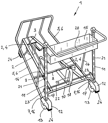
The luggage trolley 1 shown in fig. 1, which is usable on escalators and
nestable with like trolleys, comprises two rear wheels 13 and a steering
caster 3 at the front end. Means 24, which are formed as supporting
parts and ensure that the luggage trolley 1 is reliably supported on a
moving escalator, are Located in the vicinity of the steering caster 3 and
in the vicinity of the rear wheels 13. The luggage trolley 1 comprises a
wheel frame 2, a loading platform 5 rising towards the front for luggage,
and rear uprights 11, the lower ends of which each carry a wheel fork 12
for mounting a rear wheel 13 and the upper ends of which carry a
pushing arrangement 20. A brake device 21 leads downwards from the
pushing arrangement 20 to the rear wheels 13, the brake device 21 being
controllable in a known manner by the pushing arrangement 20. The
brake device 21 comprises a transversely extending, pivotable release rod
22 which releases the brake device 21 of the respective preceding luggage
trolley 1 when a plurality of luggage trolleys 1 are nested in a row, i.e.
CA 02469867 2004-06-09
4
parked. The front portion of the wheel frame 2 carries the steering caster
3. The loading platform 5 has two longitudinal members 6 which are
each welded to a wheel fork 12 at their rear end 7. Supporting struts I4
extend upwards from the two longitudinal members 6 and are welded~to
the two uprights 11 and optionally carry a basket 15 for holding small
items of luggage. A crossbar 10 is provided above the connection points
16 of the longitudinal members 6 and the wheel forks 12 and is welded
to the two wheel forks 12. The connection points 17 between the
crossbar 10 and the wheel forks 12 are arranged higher than the
connection points 16 between the longitudinal members 6 and the wheel
forks 12, Two longitudinal members 4, forming part of the wheel frame 2,
are welded to the crossbar 10. The wheel frame 2 slopes downwards
slightly towards the front. Close to the supporting struts 14, the loading
platform 5 is provided with a transverse strut 8. Two small supporting
parts 9 lead from the transverse strut 8 to the longitudinal members 4 of
the wheel frame 2, the longitudinal members 4 being welded to the
transverse strut 8 of the loading platform 5 by means of the supporting
parts 9. A stop device 18 extends rearwards from the transverse strut 8.
The stop device 18 is arranged between the uprights 11 and is
additionally welded to the crossbar 10. The stop device 18 has a closed
portion 19 through which extends the release rod 22, the ends of which
are each connected to a pivoted lever 23 forming part of the brake device
21.
Fig. 2 clearly shows that the wheel frame 2 sloping downwards and the
loading platform 5 rising upwards intersect one another. It can be seen
that the loading platform 5 is connected to the wheel forks 12 and the
wheel frame 2 is connected to the crossbar 10 leading into the wheel
forks 12. The distance A shows that the connection points 16 betyveen
the loading platform 5 and the wheel forks 12 are arranged lower than
the connection points 17 between the wheel frame 2 and the crossbar 10.
CA 02469867 2004-06-09
All other technical details which have not been described here can be
drawn from the initially mentioned prior art.