Note: Descriptions are shown in the official language in which they were submitted.
CA 02470032 2004-06-04
2003P08138US WER
Patent~Treuhand--Gese7.lscha~t
~ur eiektrische G~,u~.iarnpen ~bi~. , I~unic~x
Title : Electric Lamp with outer buYb aaad associated
support bod3r
~ec~a~ical ~ie:a.d
Reference is made to applicat_~on with docket no.
2003P08248DE filed in parallel, which provides a more
detailed description of processes for producing a lamp
with a Better strip.
The invention relates to an electric lamp with outer
bulb and with an inner vessel, in particular a
discharge vessel, arranged therein, a Better material
being held on a support body inside the outer bul b. It
deals in particular with discharge laves, such as :metal
halide lamps, but also with incandescent halogen lamps.
Eackground Art
US-A 5 825 127 "nas disclosed a process for producing a
cap strip for discharge lamps, in which the cap strip
is a support strip comprising a mater~_al which is to be
introduced into the lamp, in particular mercury and/or
Better material as a coating. The on__y application area
envisaged for cap strips of this type in that document
is as the discharge vessel of a low-pressure mercury
lamp. In this case, the cap strip is often secured in
the vicinity of an electrode, cf. in this :aspect also
US 6 043 603. A support strip with Better is also
referred to as a Better strip.
An example of an incandescent halogen lamp with a
Better in the outer bulb is to be found in
CA-A 1 310 058.
CA 02470032 2004-06-04
- 2 -
Letters are usually used on a disk as a base in the
outer bulbs of high-pressure discharge lamps in order
to absorb impurities. Far example US 5 327 042 uses a
2r Better on an iron sheet base which is securely
welded to the frame. In the case of discharge vessels
which are closed on two sides in an outer bulb which is
closed on two sides, Betters are usually secured in the
pinch of the outer bulb using a piece of wire or at the
outer supply conductor or at a sheet-metal shell placed
around the pinch of the discharge vessel, cf. in this
respect Technisch wissenschaftliche Abhandlungen der
OSRAM-Gesellschaft, Vol. 12, Springer-Verlag, Berlin
1986, pp. 11 to 14.
Disc.lc~s~are ~f the Inve~s~i~r~
It is an object of the present invention to provide an
electric lamp with outer bulb ar_d with ar_ inner vessel,
in particular a discharge vessel, arranged therein, a
Better material being held on a support body inside the
outer bulb which -.~a.mp allows simple9 inexpensive and
space-saving securing of a Better in the outer bulb. A
further object is to provide a support bcdy which is
particularly well adapted and in particular is
especially suited for this purpose.
This object is achieved by the feature that the support
body is a support strip to which the Better material is
applied, the support strip being curved in such a way
that it is automatically held in the outer bulb without
the need for any auxiliary means. Particularly
advantageous configurations are to be found in. the
dependent claims.
The electric lamp according to the invention has an
outer bulb and an inner vessel which is arranged
therein and is closed off in a vacuum-tight manner,
generally a discharge vessel. It is usually held in the
outer bulb by means of a frame. However, the lamp may
CA 02470032 2004-06-04
- 3 -
also be an incandescent halogen lamp with an outer
bulb. A Better material i_s held on a support body in
the outer bulb, the support body being a support strip
to which the Better rttaterial .s applied as a layer, as
is known per se from US 5 825 127. According to the
invention, however, the support strip itself is used
directly as a holding mechanism, with the support strip
being bent in such a way that it is automatically held
in the outer bulb without the need for any auxiliary
means.
The invention may be realized in various ways; in one
embodiment, the support strip consists of flexible
material. In this case, a simple holding mechanism can
be produced by the discharge ~ressel hawing at least one
pinch, with the support strip being wrapped around at
least part of the pinch. If the inner vessel, which is
generally a discharge vessel,, has at least one fused
seal, the support strip is wrapped around at least part
cf the fused seal.
In a second embodiment, the support strip consists of
elastic, resilient material, in particular of spring
steel. With this condition, it is possible for the
support strip to be held on the inner surface of the
outer bulb by spring forces alone.
Reliable holding is achieved if the support strip is
clamped into notchev; in the inner surface of the outer
bulb.
One alternative is f_or the support strip to be bent in
such a way that it has at least three bearing points
against the inner surface of the outer bulb.
A further embodiment req~,aires the support strip to be
perforated and tc be secured to the discharge vessel in
a clamping fashion by bending at the perforated
locations. In this case, of course, the support strip
CA 02470032 2004-06-04
may additionally be resilient or at least flexible.
Particularly secure holding of the support strip in the
outer bulb is achieved by virtue of the outer bulb
being provided with a bulge which assists with secure
holding of the support stripo
A particularly preferred embodiment, in which the
advantages of the novel concept manifest themselves
particularly clearly,, is an arrangement in which the
discharge vessel is closed off by sealing parts at
opposite ends, with the outer bulb only partially
surrounding the discharge vessel and ending in the
region of the sealing parts at the latest.
One typical application is metal ralide lamps and
incandescent halogen lamps.
Br~.ef descri~tl.on of the davwa.ngs
The invention is to be explained in more detail below
with reference to a plurality of exemplary embodiments,
in which:
Figure 1 shows a side view, in section, of a
metal halide lamp;
Figure 2 shows a production process, in highly
diagrammatic form, for the lamp shown in
Figure 10
Figure 3 shows a metal halide lamp in cross
section with support strip;
Figures 4 to 9 show further exemplary embodiments for
lamps with support strip in cross
section;
Figure 10 shows a plan view of an exemplary
embodiment of a perforated support
stripo
best mode for c~rryinc~ out the iwsrentiors
CA 02470032 2004-06-04
- 5 -
Figure 1 shows a side view of a metal halide lamp 1
which is pinched an twa sides. The discharge vessel 2,
which is designed as a barrel-like body made from
quartz glass, encloses two electrodes 3 as well as a
metal halide fill. The bulb ends are sealed by pinches
4 in which foils 5 are embedded. 'The foils are
connected to external supply conductors 6. The external
supply conductor 6 is guided inside a tubular sleeve 7
and ends in a bush 8 of an integral cap part 9. The' cap
is produced as a single part from steel and also
comprises a circular disk 10 as contact element and
barb 11 as centering and holding means. The part of the
discharge vessel which bulges out is surrounded by an
outer bulb 12 whi ch i s rolled on (13) in the region of
the transition bet~Yaeen the pinch 4 and the sleeve 7.
The outer bulb 12 ~nas an encircling indentation 14, so
that an elastic support strip 15 made from iron, in
particular nickel-plated, or steel is spread apart
against the inner surface of the outer bulb without
being able to slip laterally. The support strip
contains Better materials, such as Zr, Fe, V~ Co, which
are used to absorb various substances, such as oxygen,
hydrogen or the like. The outer bulb may be filled with
nitrogen, another inert gas or vacuum.
One possible form of production is described, for
example, in US 2002/003 529, US 2002/07 115 or US-A
5 128 589. A variant with a complete outer bulb is
indicated, for example, in CA 2 042 143. The concept of
the invention can be used for all these designs.
A further production method is described below with
reference to Fig tae first of all, the discharge
vessel 2 is completed from a cylindrical tube by means
of a forming roll and if appropriate pinching jaws,
which in each case fix an electrode system which has
been introduced into the still-open tube, for example
by pinching, unt~.l the stage at which it has been
CA 02470032 2004-06-04
-
provided with a seal (pinch 4 or fuse seal) at both
ends. At the same time, integrally attached, sleeve-
like extension parts 7 remain in place at the seals.
While a first extension part 7a is being closed up by
the end 16a, which is initially stall open, of the
extension part being dropped onto a cap part 17 which
has been introduced, a pumping hole 18 remains opE:n at
the second extension. part 7b. Moreover, the open end
16b is not initially treated. Irl parallel, the
cylindrical outer bulb 12 is pretreated until an
encircling indentation 14 laterally fixes a support
strip clamped next to it in the outer bLllb 12. The ends
of the outer bulb are then rolled onto the extension
part 7 on both sides by means of prior heating by
1 5 flames (,arrow P1~ , specifically in such a way that, the
fixing at the end 16b of the second extension part 7b
takes place outside the still-open pumping hole 18. At
the height of the pumping hole 18, a1_though the outer
bulb 12 is rolled in down to a fraction of its original
diameter, it is not yet rolled in to such an extent
that it bears against the exter~.sion part 7b (arrow P2).
At the still-open end 16b of the second extension part
7b, this arrangement is connected via a feedline 38 to
a pumping and filling system 39, i.n particular by a
pumping rubber 40 being fitted to the end of the
extension part. The atmosphere in the outer bulb can
then be evacuated. The pumping path is indicated as
arrow P3. Then, the outer bulb 12 care be supplied with
a substantially inert atmosphere via this pumping path
or a vacuum can be maintained. In the next step, the
pumping hole 18 is closed up, either by being closed by
rolling, being melted shut by means of a laser, or
simply by material automatically dropping onto it after
heating under the application of reduced pressure.
Then, the end 16b of the second extension part is also
"shrunk on". The Better strip 15 may, if necessary for
the Better used, subsequently be activated through the
outer bulb 12 by means of a laser..
CA 02470032 2004-06-04
- 7 -
Instead of an indentation 15 as an inwardly facing
bulge as the lateral boundary, it is also possible to
use an outwardly facing bulge (52) in which the support
strip is guided ors account of the two-part lateral
delimitation, cf. Fig. 2b.
Figure 3 shows the principle of a further way of
securing the support strip. In this case, the support
strip 20 is secured directly to the i~-shaped pinch 21
(srown in cross section) by being bent in such a way
that two contact sections 22 thereof touch the two wide
sides 23 of the pinch 21 in a clamping manner, whereas
a central secticn 24, located between them,. of the
support strip surrounds a first narrow side 25 at a
distance therefrom. The free ends 26 of the support
strip protrude towards 'the second narrow side 27 at the
pinch.
A similar concept can also be used for a lamp with a
fused seal 28. Figure 4 shows a cylindrical fused seal
28 in section, The support strip 29 with Better
surrounds the fused seal 28 virtually completely,
specifically it surrounds at least three quarters of
its circumference, bearing against it at at least three
points. The free ends 30 of the support strip are bent
back through approximately 330° and are also angled off
through approximately 90° at the direct end, with these
free end pieces acting as a fitting aid.
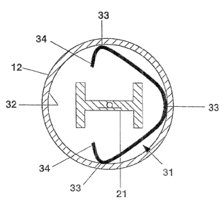
Another concept is shown in Figure 5. In this case, the
support strip 31 is not secured to the pinch 21 (cr
fused seal) , but rather to the inner surface 32 of the
outer bulb, by virttae of the support strip being formed
from spring steel or nickel-plated Iran approximately
as an isosceles triangle with rounded corners 33 and an
open base 34. The rounded corners form the three
contact points with respect to the outer bulb. To be
held securely, it is advantageous if the three contact
points span slightly more than half the circumference
CA 02470032 2004-06-04
of the outer bulb, in particular approximately 55 to
750. The temperature to which the support strip is
exposed, on account of its proximity to the discharge
vessel, is in this case relatively high, and
consequently this configuration is eminently suitable
for getter materials which require a high temperature
in order to be effective. This concept is also
eminently suitable for fused seals, since fused seals
take up less space than finches.
A second variant s:nown in Figure 6 is designed for
Betters which require a relatively low temperature to
provide an optimum efficiency. In this case, the
support strip 35 is nestled significantly more closely
i5 to the inner surface 32 of the outer bulb. For this
purpose, the support strip 35 is bent approximately in
a C shape, so that it acquires a further distance from
the pinch 21 of the discharge Vessel.
Figure 7 shows a further embodiment. In this case, the
support strip 3a is clamped between two slots 37 at the
inner surface 32 of the outer bulb, so that it is
curved in a -roof shape. The two slots 37 are arranged
slightly eccentrically with respect to an imaginary
parallel diameter D, with this connecting straight line
V between the slots being offset with respect to the
parallel diameter D to such an extent that it lies
approximately at they height of the ends of the narrow
sides of the H-shaped pinch 21. The spring stress is
preferably selected in such a way that the support
strip 36 has a length of approximately 120 to 1600 of
the length of the connecting straight lines V between
the slots 37.
A further embodiment uses a perforated support strip 41
for securing to the discharge vessel 42, so that the
bends in the support strip can be better matched to the
shape of the H-shaped pinch 2~. Figure 8 shows a
support strip 41 which, in a sim~_.iar manner to in
CA 02470032 2004-06-04
g a
Fig. 3, is clamped securely to two wide sides 43 of the
pinch, with a central section 44 surrounding a narrow
side 45. Unlike in Figure 3, however, suitable
perforation of the support strip allows the central
section 44 of the support st rip to run parallel to the
narrow side 45 and then to be bent off at right angles
toward the wide sides. There, contact with the wide
sides is effected in each case by means of an end
section 46 which is V-shaped in form. In this way, the
space taken up by the support strip is considerably
reduced. This embodiment is particularly suitable for
getters with a high working temperature and for lamps
with a short distance between the outer bulb and the
discharge vessel.
Figure 9 shows an exemplary embodiment of a perforated
support strip 47 which is secured to a fused seal. 28.
Compared to Fi gure 4, the perforation allows a shorter
support strip 47 to be used. The support strip is
wrapped around the fused seal, which is cylindrical in
cross section, over approximately 70 to 900 of its
circumference, with five lines of perforations allowing
sharp ends 48 to be made in the support strip. This
makes the holding
more reliable and
more tightly
fitting. There is no need for an extension as a fitting
aid, as in Figu re 4.
Figure 10 diagrammatically depicts a perforated support
strip 47. In the unbent state, it is a metal sheet
which has been cut at right angles and to which a
Better mater? al 49 has been applied, for example as a
centrally running ribbon. In. the exemplary embodiment
shown (left-hand half), by way of example, five slots
50 have been punched into the support strip as
perforation lines. Of course, the perforation may also
be configured differently, for example may be formed by
rows of stamped holes 51 along a line, as shown in the
right-hand half of Figure 10. The number of lines of
perforations depends on the number of desired bends.
CA 02470032 2004-06-04
- I0 --
The stamped holes have the advantage that they can be
formed over a greater proportion of the width of the
metal sheet than the slots. On the other hand, the
slots, the length of which is greater than the width of
the Better-containing ribbon 49, Nacre the advantage
that it is impossible for any Better material, for
example zirconium oxide, to flake off or crumble away
when the metal sheet is being bent.
Of course, this technique can also be used for
discharge vessels which are closed on one side, in
particular pinched. This may be accommodated in an
outer bulb which is c~_osed on one aide. Accordingly,
the technique can also be used for a discharge vessel
which is closed on two sides in an outer bulb closed on
one side.