Note: Descriptions are shown in the official language in which they were submitted.
CA 02470039 2004-06-04
Eir~~~~u ~~~ ~~~rA~~ii~~~ ~~~ H~I~ ~LIi~P~~
A~KRC~Ui~~ ~>F ~HINr~~~ITIN
'The present invenKion relates generally to hair dipping devices used for
trimming facial hair, whether manually operated or powered. Specifically, the
present invention relates to such trimming devices intended for use in
trimming
eyebrows.
It is not uncommon tra use a pot~rered hair trimmer or hair clipper for
trimming the hair of one's eyebrows. Hlowever, one drawback to the use of a
power trimmer around the eyes is that the clipping;; generated ~n the (rimming
process can become caught in the eye and be irritating to the user. ,mother
applicable to individuals whose brow ridges do not extend far beyond the outer
margin of the eye. In other words, for individuals with relatively deep-set
eyes,
the issue of the clipper blades coming in close contact with the eye is less
~f an
issue.
~llhiie it is known to use conventional trimmers or dippers having
g attachment combs for trimming eyebrow hair, one disadvantage of that
application is that the relatively wide cutting blade of such devices risks
cutting
CA 02470039 2004-06-04
any hair of the normal head hair which happens to be ors the forehead or in
close
proximity to the eyebrow area. Another drawback of using conventional hair
trimmers with combs for eyebrow trimming is that the relatively wider blade
Inherently entails comb teeth which typically extend tire full width of the
blade,
which may come in close proximity to the eye.
Still another concerrr for individuals using electric or powered trimmers for
trimming eyebrow hair is that in some cases, the trimming edge of tile blade
is
obscured either by the clipper itself, or the individual's hand. If possible,
visibility
of the cutting area through at least one and preferably both eyes is
preferable in
'I ~ accurately achieving welhtrimmed eyebrows.
Thus, there is a need for a device for trimming eyebrow hair which
facilitates the use of a hair trimmer and which helps prevent hair clippings
from
entering the eye. In addition, there is a need for a device: for use with a
powered
hair trimmer design for eyebrow trirr~ming in which the clipper or trimmer
blades
1 b are prevented from coring in contact with the user's eye.
SI~IEF SIJ~IIMA~Y ~3F T~fE IIV~'IVTI~I~
The abovepider~tied needs are addressed by the present eyebr~w comb
attachment for a hair clipper, which is removably attachable to a conventional
hair
trimmer or hair clipper blade end. The attachment s~f the present device is
similar
20 to that of a conventional attachment comb. one feature of the present
attachment
is a blade guard for obscuring, rr~asl<ing or blocking r~°~rach c>f the
width of the cutting
CA 02470039 2004-06-04
b clippings from entering the eye. ~ti!! another feature of the present
eyebrow comb
attachment is the provision of comb teeth for guiding eyebrow hair into the
relatively
narrow, unobscured or exposed cutting area where the blades are available for
cutting.
More specificallyQ the present invention provides an eyebrow comb
attachrr~ent for attachment to a hair clipper having a bladeset with a roving
blade
laterally reciprocating relative to a stationary blade, includes a guard
'Formation fnr
blocking access to end portions of the bladeset and defining a cutting area
between
the end portions, and at least one deflecting formation associated with the
guard
forrnation for deflecting hair clippings generated by action of the biadeset
in the
cutting area. ~'he attachment preferably incl~des~ at least one guide
f~rmation
associated with the cutting area and configured f~r guiding hair into the
cutting area
for clipping.
BRIEF I~ESGI~IPTl~i61 ~F ~°HE ~31~r111~lNCi~
Fl(~. 1 is an elevatior'al view of a powered hair clipper fitted with tl~e
present eyebrow comb attachment and being used on a users' eyebrc~w8
Fl~. 2 is an overhead plan view of the attachment shown in F9~. 1;
CA 02470039 2004-06-04
DETi4i~.E~ DE~~RiPTi~N (5F THE lNV'ENTIC?N
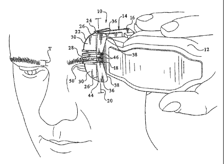
Referring now to FI~. ~ , a powered hair clipper or hair trimmer (here used
interchangeably} suitable for use with the present attachment is generally
designated 10. Included on the clipper ~ 0 is a housing 12 enclosing a power
source
knot shown} preferably an electric motor, powered by line voltage or batteries
as is
well known In the art. i~hife a powered hair clipper 9 0 is depicted, it is
blades 1 fi, 18 have a plurality of teeth, and the reciprocal rr~oveaner~t of
the blades
causes cutting action along a cutting line 20 extending ths~ width of the
blades. As
is mown in the art, such clippers 10 are v~idely used for personal groors~ing
such as
hair cutting, beard and rreustache trimming and eyebrornr trimming.
~0 For facilitating eyebrow trimming, and for addressing some of the abvve-
identified needs, the present eyebrow comb attachment 22 is releasably
attachable
CA 02470039 2004-06-04
to the bladeset 1~, preferably to the stationary blade fig. The attachment 22
is
specifically designed o help prevent cut hair front 'failing into the user's
eyes, for
protecting the user's eyes from contact with the bladeset 94 and for guiding
eyebrow hair into the blade;set for cutting. Further, the profile of the
attachment 22
b is designed to minimize the obstruction to the user's field of view when
using the
product, at the sarr9e ticrae providing adequate blocking and deflecting of
hair
clippings. In the preferred embodiment, the attachment 22 is integrally moEded
from
a suitably durable plastic ~°naterial, however other rrsaterial;~ are
contemplated as are
known in the art.
1d E~eferring now to Fl~s. 1~5, included on ~tl~°~e attachment 22 is a
guard
formation 24 configured for blocking or masking the operation ofthe biadeset ~
4 for
a significant portion of the bladeset width. It is desirable i~or the bladeset
14 to cut
hair only the approximate freight or thickness ~°'T"} of an eyebrow to
minimize the
possibility of stray heed hair being inadvertently cut, and for protecting the
user's
1~ eyes frost unwanted contact with the biadeset ~~.. Thus, in the preferred
embodiment, the guard formation 2~. is configured to overlie a significant
portion of
cutting edges of the bladeset 1~.9 preferably in two spaced apart end portions
26
which block access to corresponding ends of the biadeset.
An exposed area referred to as the cutting area 2~, located bet~nreen the
CA 02470039 2004-06-04
cutting area of the bladeset f 4 is blocked. It is contemplated that other
dimensions
for the cutting area may be desirable depending ors the application or the
width of
the clipper or trimmer blades.
Another feature of the attachment 2~ is at least one deflecting formation
associated with the guard formation 2~. for deflecting fcair clippings
generated by
action of the bladeset in said cutting area. In the preferred embodinnent,
there are
i~ro such deflecting formations, a first is referred to as a fan rib 30 v~hich
projects
from the Sine ~0 in a first direction from the guard vorrnation 2~4, or
forvrard of the
guard formation as the clipper ~ 0 is ~ie~red in Fl~~,. ~ . The fan rib 3g is
provided
~fg adjacent at feast one side of the cutting area 23, and preferably in tvvo
portions
separated by the cutting area ~3. In addition, the fan rib 30 is dirx~ensioned
t~
provide deflecting of hair clippings away from the user's eyes, ~rhiie at the
same
time providing adequate visibility of the cutting area, as the user observes
the
cutting action in a mirror. Accordingly, the fan rib 30 is pr~~rided with a
curved and
radiused forward edge 32, and a generally straight rear edge 34. along the
attachment line to the guar~~ formation ~4. °hen wiewee~ frorn above,
the fan rib
defines a general a~"-shape (best seen in FICA. 2~. The forward edge 32, as
veil as
ail other exposed edges of the attachment 22, are preferably radiused or
rounded
for facilitating movement alr~ng the skin andfor in tl~e hair of the user.
A second deflecting formation Is at least one defleci;ing surface .3g in
closely
spaced relationship to the moving blade '!8. In the preferred ernbodirr~ent,
the at
least one deflecting surface 36 includes a pair of said surfaces disposed on
either
side of the cutting area ~3, tt~e surfaces 3~ having a profile cfln~gured for
providing
ti
CA 02470039 2004-06-04
seen in the Fl~s., the fan rib 30 is a deflecting formation projecting from
the cutting
line 2D in a first direction, and the at least one deflecting surface 36 is at
least ore
second formation projecting frog the fire ire a secorvd dire~,tiot~ distinct
from the first
direction.
Referring nowto FI~. 5, anotherfeature ofthe at least one deflecting surface
3fi is that a spaced relationship is defined relative to an upper end 42 of
the moving
blade °! 3. ~°he deflecting sa~rfaces 35 are secured to, .and
preferably integrally
formed with, the guard f~rmatlor~ 2~.. IVlore specifically, the guard
forrt~atlc~n 24
Includes a leading edge 44 which forrvs a generally forvrard projecting vredge
or "~i"-
'l 5 shape corresponding to a pr~ofife when viewed from the side defined by
the bladeset
~t~ depending on, arr3ong other things, the profile of the; biadeset ~ 4, the
speed of the
clipper 1fl, and the desired arrtount of deflection, depending ors the
application.
Ir't a further preferred embodiment, It is noted that the fan rib 30 is also
inclined relative to the plane '~~°' of blade reciprocation (Ft~. 5~.
l~ihiCe the degree
CA 02470039 2004-06-04
of inclination rrsay vary to suit the application, it is preferred that the
degree of
inclination of the fan rib 0 to the plane !~ and to the bladeset 94 will be
the same
as the degree of inclination of the deflecting surfaces ~5.
Referring nowto FIGS. ~ and ~, additional d~:fCecting is prcvideci between the
deflecting surfaces 3fi by at least one spaced deflector pad 4~6 disposed in
the
°IO In the preferred embodiment, the deflector pads ~6 are located at
ends 45
of each of at least one guide formation ~0 associated with the cutting area 2~
and
configured for guiding hair into fihe cutting area for clipping. i'referably,
as is known
in the attachment comb art, the afi least one guide formation 50 is a
plurality of
spaced comb teeth having generally pointed Taut radiused and thus lalunted)
tips 52
best seen in FIG. 3). each tooth 50 has a generally s~lid tooth ~nrall 5~
~Fi~. 3) with
a radiused border edge 5b, and is secured at its root 55 FIG. 2) to a base 60-
of the
guard formation 24. !~s seen in FIG. , lower edges 5~ c~fthe comb teeth 50 are
curved as is known in the art to follow the surface of the brow ridge on the
user's
head.
2Q Referring now to FIGS. 2 and 3, it will be seen that the outerm~st teeth
5~a
and 50b are attachment paints for corresponding edges fit of the fan ribs 30.
Thus,
in the preferred embodiment, the fan ribs 3Q extend firot~ the leading edge 44
of the
guard formation 24. to the corresponding outermost teeth 50a, 50b. It has been
CA 02470039 2004-06-04
rear end fi4. At the rear end 6~, a connection forrnatior~ preferably taking
the forrr~
of a generally rtormaliy~extending latch rr~all 6fi including a latch lug 6~
fc~r engaging
the stationary blade 1 S. Further, it is preferred that at least one gripping
forrnatior~
7~ for facilitating the removal of the attachment 2~ from the clipper 10.
15 In operation, arid referring rso~nr to FILE. 1, upon attachment to the
clipper 10,
the present attachment ~~ substantially blocks the teeth of the biadeset due
to the
wedge shaped leading edge 4 of the guard formaflort ~4. ~nly at the cutting
area
2$ are the blades 1 fi,1 ~ e~cposed and available for trimming. This enclose
re of the
blades 1 ~, "I , protects the usec~s eyes from the blades therr~selves and
a1s~ from
2g clippings generated during the trimming process. The cutting area 28 is
dimensioned to be about as ~nride as the eyebrov~r. ~s the clipper 1 C3 is
moved along
the eyebrow, the guide teeth b0 guide hair into the cutting area 2~ for
trirr~rr~ir~g by
the blades 16, °i ~. clippings are deflected by combined action of the
fan rib 3D, the
g
CA 02470039 2004-06-04
deflecting surfaces 3~, as well as the deflector pads ~6. mother operational
characteristic ofthe present attachment 22$ particularly when used in the
orientation
of Fly. 1, is that clippings pass through spaces 2 (FIG. 2~ between adjacent
deflector pads 46 and between the pads 40 and the deflecting surfaces 36. By
.5 e~ltit~g through thaw spares '2, the clippings are more easily prevented
from
reaching the eye area.
P~nother feature of the present eyebrow comb attachment 22 is that it
perforrns thefunctions ofguarding the eye, deflecting clippings and guiding
eyebrow
hair into a relatively narrow cutting area while minimizing the overall
profile of the
unit. T'h~s, visibility of the cutting area by the c~ser is dept reasonably
open.
Thus, it wil! be seen that the present attachrner~t 22 facilitates the use of
a
standard clipper 10 for trimming eyebrows. Clippings are deflected away from
the
eyes and radiused edges protect the eyes from the attachment starfaces as wel9
as
the bladeset 14. In addition, the overal! shape of tl~e attachmerEt is
configured for
providing sufficient deflection and protection, while also providing
visibility of the
eyebrow area by the user.
Vilhile a particular embodiment of the present eyebrow comb attachment for
hair clipper has been described herein, it will be appreciated by those
spilled in the
art that changes and modifications may be made thc;reto without departing from
the
invention in its broader aspects and as set forth in the following claims.