Note: Descriptions are shown in the official language in which they were submitted.
CA 02470097 2004-06-11
WO 03/052959 PCT/US02/37825
(0001( Sl'STE\'1S :ADD f~-1ET1-IUDS I~OR i'It0\~ID1\~G hCL-iO C~t~\~~I~ROL
(0002] FIL:Ln OF Tl-lE l~\'E\TIO\
(0003) The present invention relates ~~en~r;tily to echo control i,n mworks
and. more
har-ticularlv. to providing echo control for voice calls trammitted ow:~
packet switched
networks.
(0004] BACKGRGL!\'D OF THE I~IVE'~ITIO\
(OOOS] Voice and voice-band traffic has traditionally L~e~n transport~.i by
circuit switched
nenworks, such a~ the public switched telephone nmwork (PST\). Tudav, an
increasine
amount of voice u~affic is carried over a combination of~ir~uit wwitched
neavorks alld
packet switched nenworks, such as Internet Protocol (IPj nm~~orks.
(U006] The PST\ typically uses both 2-wire circuits and rt-wire circuits for
carrying full
duplex voice traffic. The 2-wire circuits are typically used in the local loop
portion of the
PST's, such as the connection from the end user to a local switch or a local
central office.
For example, a voice call from a typical telephone may be routed to ., switch
over the
PST\ as an analo'z signal on a standard two-wire circuit. .-\t the switch. a
hybrid circuit
may convert the ?-wire circuit connection to a 4-wire circuit connection. The
switch may
also forward the voice call to one or more conventional gateways that provide
various
services associated with transmitting information over an IP nehwork. For
example, the
~atevway may convert analog voice signals in pulse code modulation (PC\t)
format into
packets for transmission over the IP nenwork. .At a second gateway. the
packetized signal
may be converted back to an analog signal. Another switch located in relative
proximitw
CA 02470097 2004-06-11
WO 03/052959 PCT/US02/37825
to the called pane m:lv include ~l hybrid circuit that converts :1 -l-wire ~
irmit to a. _'-w ire
circuit for connection to tllr called party's l~:lephone.
~0007~ One problem with t! ansmittin~ ~,~oicc data in this manner is th;lt mho
stay ucrur as
a I'eslllt Of IIllped311Ce 1111~i11:11C17 ~tl lily 11', brt0 CIrCIIIIS, l.e..
llle pOllll ~~ ll~e llle ~-w 11'e
circuits are converlwd to -t-wire circuits and vice versa. This echo is oaten
perceivable by
the hllillall ear and ultimately degrades the quality of the voice call.
Conventional
gatewa}-s may include integrated echo cancellers to combat echo. That is, the
gateways
themselves perfoml echo cancellation.
(0008] One problem with gatwvays that include integrated echo cancellers is
that they
oaten do not support the tone disables function. The tone disables function
reicrs to a
1 UO Hz tone with phase reversal that is generated by a data modem. This tone
is
typically used to disable echo cancellers since echo cancellers often
interfere with
voiceband data traffic. Since the gateways do not support the tone disables
function,
voiceband data traffic cannot be supported over the network.
(0009] Another problem with gateways with integrated echo cancellers is they
often fail
to introduce "COIllt01't~~ noise alter echo cancellation has been perfonlled.
This results in
the listener perceiving a loss of connectivity. In addition. the conventional
gateways
often do not adhere to the echo cancellation convergence criteria specified by
the
International Telecommunication Union (ITU) 6.168. As a result. the echo may
be
objectionable in voice calls made over an IP network.
[0010] SUW\iARI' OF THE I\'VE\T10\
(0011 ] There exists a need for systems and methods that improve problems
associated
with echo control in an IP network.
CA 02470097 2004-06-11
WO 03/052959 PCT/US02/37825
;0011) These and other needs arc ntet by the pre~.mt invention, where sUtnd-
alone c~ho
~:,tncellcr; are strafe«icallv located to perform echo eancullation. By
lomltin~ the echo
~,tnrcll~rs at particular !ovations, the echo problem ntay be eliminawd or
substantially
~~c~iuced, tlterety, improvip~ the quality of \'OICe CaIlS 1r31151711t1~d over
an IP nom ork.
;t1013J According to one aspect of the invention. a sysmm that includes a
first echo
~anceller, a first gateway, a second v~atewav and a second echo cancell~r is
provided. The
first echo canceller is coupled to a first switch in a circuit switched
network and is
coati<aured to cancel echo associated with voice calls transmitted over a
circuit switched
nmvork and a packet switched network. The first gateway is coupled to the
first echo
canceller and is configured to forward a first voice call owr the packet
switched network.
The second gateway is coupled to the first gateway via the packet switched
network and
is configured to receive the first voice call from the first gateway via the
packet switched
network and forward the first voice call to a second switch in the circuit
switched
network. The second echo canceller is coupled to the second gateway and the
second
switch and is configured to cancel echo associated evith voice calls
transmitted over the
circuit switched network and the packet switched network. The second echo
canceller is
configured to cancel echo associated with the first voice call when a time
associated with
transmitting a first voice signal is greater than or equal to a predetermined
threshold.
(0014( Another aspect of the present invention provides a method for
cancelling echo in
a voice call from a first party to a second party, where the voice call is
routed from the
first party to the second party over circuit switched and packet switched
networks. The
method includes fowarding the voice call from the first party to a first
switch included in
a first circuit switched network, where the first switch includes a hybrid
circuit that
3
CA 02470097 2004-06-11
WO 03/052959 PCT/US02/37825
converts a wo-wire circuit to ~ four-wire circuit. T~I1C Illethod ,tl,o
m~!tiiius tran~m:ttint~
the voii:c call over the lour-wire circuit to a first gateway. convertintT.
:~t the lirst '~~~teway.
tltc voice call to a format compatible ~.vith the packet switched nmvork, and
transmutin~~
tl;e voice call over the packet switcl-~ed network to a second gateway. Tlte
IllelhOd further
incU.ides converting, at the second «atwvay, the voice call to a format
compatible w ith a
second circuit switched neavork and transmitting the voice call to a second
switch
included in the second circuit switched network. The second switch includes a
hybrid
.ciucuit that convents the four-wire circuit to a two-wire circuit. The method
also includes
forwarding the voice call to the second party, where a portion of the voice
call reflects
back at the second switch toward the first party, and cancelling the reflected
portion o1
the voice call using an echo canceller. The echo canccllen is located
cxmrnally ti-om each
of the first switch, the second switch. the first gateway and the second
gateway alld is not
controlled by any of the first switch, the second switch, the first gateway
and the second
gateway.
[OOI~J ~ccordina to a further aspect of the invention, a method for providing
echo
control in a system that routes voice calls over a circuit switched new~ork
and a packet
switched network is provided. The method includes identifying echo sources in
the
system. The method also includes determining whether a first time associated
with
transmitting a first signal from a first one of the echo sources over a voice
path that
traverses both the circuit switched and packet switched neW ~orks and
receiving a
retlected portion of the first signal at the first echo source is greater than
or equal to 3~
milliseconds. The method further includes determining whether a second time
associated
with transmitting a second signal from a second one of the echo sources over
the voice
CA 02470097 2004-06-11
WO 03/052959 PCT/US02/37825
path and receivine a reflected portion of the second signal at the mound cvho
;our~c is
greater than or equal to 35 milliseconds. The method also includes inserting
lirst anii
aecond stand-alone echo eancellers on the voice path when the lint and second
tinms are
both Ur~atcr than or equal to 3~ milliseconds.
(0016] Other features and advantages of the present invention will become
readily
apparent to those skilled in this art from the following dmailed description.
The
embodiments shown and described provide illustration of the best mode
contemplated for
aarryin~ out the invention. The invention is capable of modifications in
various obvious
raspects, all without departing from the invention. .Accordingly, the drawings
are to be
reUarded as illustrative in nature, and not as restrictive.
(U017] BRIEF DESCRIPT10?~ OF THE DRAB\'I\GS
[0018] Reference is made to the attached drawings, wherein elements having the
same
reference number designation may represent like elements throughout.
(0019] Fig. 1 is a block diagram of an exemplary system in which methods and
systems
consistent with the present invention may be implemented.
[0020] Fig. 2 is an exemplary flow diagram, consistent with the present
invention,
illustrating processing for determining whether external echo cancellers are
needed in the
system of Fig. 1.
[0021] Fig. 3 is a block diagram of an exemplary system, consistent with the
present
invention, which illustrates the insertion of external echo cancellers in the
system of Fib.
1.
CA 02470097 2004-06-11
WO 03/052959 PCT/US02/37825
J0022 J Fi'~. -1 i' a block dia~~ram ot~ another e~:rmplan w>tcm ~n w ill~Il
nmllod> aml
systems consistent with the present invention may be implemented.
[0023] Fig. ~ is an exemplary flow diagram. consistent with the present
invention.
illustrating processing for determininU whether external echo c:~mellers are
needed in the
system~of Fig. ~.
(002] Fig. 6 is a block diagram of an exemplary system. consister;t with the
present
invention, which illustrates the insertion of external echo cancellers in the
s~~snm of Fig.
[002] Fig. % is a block diagram of another exemplary system in which methods
and
systems consistent with the present invention may be Implemented.
[0026] Fig. 8 is a block diagram of an exemplan- system. consistent with the
present
invention, which illustrates the inset~tion of external echo cancellers in the
system of Fig..
7.
[0027] DETAILED DESCRIPTIO\
[0028] Systems and methods consistent with the present invention avoid the
problems
associated the occurrence of echoes for a voice call transmitted over a mixed
PST\; IP
network by providing echo.cancellers located externally from the various
switches and
gateways in the network. By strategically locating the echo cancellers,
problems
associated with echo may be avoided.
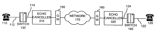
[0029] Fig. 1 is a block diagram of an exemplary system 100 in mhich methods
and
systems consistent with the present invention may be implemented. The system
l00
includes telephones l 10 and 120, switches 130 and 1~0, gateways 1 ~0 and 160
and
6
CA 02470097 2004-06-11
WO 03/052959 PCT/US02/37825
ncw~ork 1?0. The eacmplarv configuration illustrated in Fi~~. I is t~or
sinnpli~iy. It
should be understood that other devices may be included in system l0u in
implementations consistent with the present invention.
[0030) The telephones 1 10 and 1 ?0 may include conventional tel~J,honcs. such
a; tl~osc
that interface with the PST\ (not showm) to place and r~ccive tel~phooc galls.
in an
exetnplarv implementation of the present invention. the connection betvee;t
telephone
1 10 and switch 130, labeled I 12 in Fig. 1, rnay be a two-wire analog
circuit. Similarly,
the connection between telephone 120 and switch 1=10, labeled 122 in Fi~~. 1.
Illa~~ be a
two-wire analoe circuit.
[0031] Each of switches 130 and 140 may represent a conventional switch, such
as a
private branch exchange (PBX) that may be located at a customer's premises.
Alternatively, switches 130 and 140 may be located at a telephone service
provider's
premises. In an exemplary implementation of the present invention, the
connection
between switch 130 and gateway 150, labeled 1 14 in Fig. 1. may be a four-wire
circuit.
In this implementation, the switch 130 includes a hybrid circuit that converts
the two-
wire circuit 1 12 from the telephone 1 10 into the four-wire circuit 1 1-1. as
illusu~ated in
Fig. I. The hybrid circuit in switch 130 similarly converts four-wire circuits
from
gateway 150 into two-wire circuits for routing the analog voice signals to
telephone 1 10.
[0032) Switch 140 may similarly include a hybrid circuit that converts two-
wire circuit.
labeled 122, to four-wire circuit 124, and vice versa, as illustrated in Fig.
1. As discussed
previously, these two-wire to four=wire hybrid circuits at switches 130 and 1-
10 may
cause echo problems as a result of impedance mismatch.
CA 02470097 2004-06-11
WO 03/052959 PCT/US02/37825
[0033] Gatewa~.~; (G~~') I ~0 and I(s0 may inclu:lc ~_onvcntional ~~.ocwws umd
to mnvrrt
input channels tuom a circuit switched new~ork into the t~ormat n~Wed for a
packet
switched new~ork. such as new~ork 170. In an eaentplarv imple;mntatiort.
;_atewws I ~~.
and 150 may be enterprise ~~atewaw that imerface v,~ith .~ partiru::;r
cuaomer'
equipment. such as the respective switches 130 and 1-10. Gateways 1 ~0 alld
I6U Illa~' be
located at the customers premises. For eaampl~. ~.~ hen switches 1 30 and i W%
arc
customer PBXs, enterprise g,atewavs 150 and 160 may be located at a customer's
premises to interface with PBXs 130 and 140, respectively.
[0034] \'etwork 170 maybe a conventional packet switched newor',;, such as an
1P
nemork. \em~ork 170 may include the Internet, an intranet, a ~V.~\, a L ~,\ or
a similar
network that transmits data packets, such as IP data packets.
[003] In an exemplary implementation consistent with the present invention, a
telephone service provider determines whether system I00 requires external
echo
cancellers, as described in more detail below. When external echo cancellers
are needed.
the echo cancellers are strategically located to eliminate or reduce echo and
to improve
voice quality.
[0036] Fig. 2 is an exemplary flow diagram, consistent with the present
invention,
illustrating processing for determining whether external echo cancellers are
needed in
system 100 of Fig. 1. Processing begins by a telephone sen~ice provider
identifying
potential echo sources in the sen~ice provider's system (act 2101. For
example, in system
100. the ?-wire to =I-wire hybrid circuits included at switches 130 and 110
are potential
sources of echo caused by impedance mismatch. Therefore. in sv~tem 100, the
telephonz
sen~ice provider may identify switches 130 and 140 as potential echo sources.
a
CA 02470097 2004-06-11
WO 03/052959 PCT/US02/37825
(0037] \ext, the telephone ser\.ice pro\ iWr iirtermines \\ Nether tl?~ round
trip dcla~.
introduced by any \~oice;echo bath in sysmn 100 is greater than a prcdetcrmimd
amount
of time (art 2?0). For example. if the round trip delay introduced by the
voice echo path
between switches 130 and i-Iti. Inbeled D in Fi~~. I. ~s ~~r~ater than
approvimatc:y ?~
milliseconds (ms), then ecl;o may be pcr~eivable by the 1?uman ear and tlla\'
ultllll~itel_,
reduce voice quality. In oti,er w ords, if the time it takes .~ signal to
travel from sw itch
130 to switch 140 and reflect back (i.e., echo) to switch 130 takes more than
25 ms, then
the quality of voice signals ~c:ceived via telephones 1 10 and 1?0 may be
reduced due to
the echo.
(0038) In an exemplary implementation of the present invention, : ~ ms has
been set as
the design criteria in \vhich echo tray be considered to be objectionable.
That is, if the
round trip delay introduced by a voice/echo path is less than 35 ms, the echo
may not be
significant enough to be objectionable and external echo cancellers may not be
needed
(act 230). If, on the other hand, the round trip delay is 3~ ms or more,
external echo
cancellers may be needed (act ?=10). In this case, the telephone sewice
provider
determines the appropriate locations) for the external echo cancellers and
inserts the
echo cancellers at these locations (act 250).
[0039] Fig. 3 is a block diagram of an exemplary system 300, consistent with
the present
invention, which illustrates the insertion of external echo cancellers in
system 100 to
combat echo problems. Referring to Fig. 3, echo canceller 310 may be located
in system
300 between switch 130 and gateway 1~0. Echo canceller 310 may then cancel
echo
associated with caller 120. That is, echo canceller 310 cancels the echo
caused by a
reflection in the signal that occurs at the hybrid circuit at switch 1.0 and
propagates back
9
CA 02470097 2004-06-11
WO 03/052959 PCT/US02/37825
toward s,vitch 1-I0. In an rvemplary imple111Cill;ltl011. CCIIO ~amcll~r 311.1
is pref~c;~ablv
located as close to the source of thi: echo as possible, which in this example
is the hybrid
aircait at switch 1 30. Therefore, echo canceller 310 may be locamd near
switch 1 ~0.
X00-IO[ Echo canceller 3'!O may be located in system 300 hmueen switch 140
anil
~~atewav 16;J. Echo canccller 3'0 may then cancel echo associated with caller
1 1U. That
is, echo cat:celler 320 cancels the echo caused by a reflection in the signal
that occurs at
the hybrid circuit at switch 140 and propagates back toward switch 130.
Similar to echo
canceller 310. echo canceller 320 is preferably located near the source of the
echo. which
in this case. is the hybrid circuit in switch 140. Therefore. echo canceller
320 may be
iocatcd near switch 140.
[0041) In system 300., when a voice call is placed from telephone 1 10. it is
transmitted to
switch 130 over a hvo-wire analog circuit 1 12, converted at switch 130 into a
four wire
circuit and passed on through echo canceller 310 to gateway 150. It should be
undet'stood that echo czncellers, such as echo cancellers 310 and 320, cancel
echo
traveling in a single direction and do not affect the voice signal traveling
on its intended
voice path. Gateway 1 ~0 may packetize the voice call into an appropriate
protocol for
nec'ork 170 and forv.'ard the voice call over network 170. Gateway 160
receives the
voice call and for'vards the voice call through echo canceller 320 to switch
140. It should
be understood that switches l30 and 140 may be included in the same or
different circuit
switched neovorks. In either case, the voice call is converted back to a two-
wire analoe
circuit at switch 140 for transmission to telephone 120. ~t the same time the
voice call is
being forwarded through switch 140 to telephone 120. a portion of the voice
call ma~~
reflect or echo back toward switch 130. Echo canceller 320 receives this echo
and
CA 02470097 2004-06-11
WO 03/052959 PCT/US02/37825
..c'lnccls" the echo (i.e., prments the echo from beltlg tr;iI15111111C~1
baC6: uvcr the ~.~uii:e
path to telephone 1 i O). In a similar manner, echo r~tnceilur 310 prevents
the echo
associated ~~~lth ;1 wOlCe Call made iron telephone I ~0 tiwm ecltoin« back to
telephone
i ~0.
[00-12J In this manner, stand-alone echo caocell~rs 310 and 3''0 are
strategically lo~amd
to prevent ei:ho ti~om reducing voice quality. In addition. in situations
where one ur both
of the gateways 150 and 160 include integrated echo cancellers, these
integrated echo
cancellers may be disabled.
J0043J In an exemplaw implementation consistent with the present invention.
echo
cancellers 310 and 320 may be conventional devices, such as Quad-Tl echo
canceliers
manufactured by Ditech Communications Corporation. :Aternatively, other
conventional
echo cancellers may be used in implementations consistent with the present
invention.
Details of the particular echo cancellers used are not described herein in
order not to
unduly obscure the thrust of the present invention. However, one of ordinary
skill in the
art would be able to select the particular echo canceller given the guidance
disclosed
herein.
(004=tJ In each case, however, echo cancellers 310 and 320 are located
externally from
the switches and gateways of system 300. For example, echo canceller 310 is
coupled
between switch 130 and gateway 150. Echo canceller 310, however, is located
externally
from these devices. Similarly, echo canceller 320 is located externally from
switch 1:~0
and ~~atewav 160.
[OOa~J In addition, the stand-alone echo cancellers 310 and 320 are not
controlled by
either the switches or gateways of system 300. For example, echo canceller 310
is not
CA 02470097 2004-06-11
WO 03/052959 PCT/US02/37825
controlled by anv particular control logic. ~urh a~ conventional Q.l I ~ c~ho
control lo~~~i~.
bein« executed at switch 130, switch 1-J0: ~~:iieway 1 ~0 or r~atewav 160.
Echo canccilcr
310 is also not tied to w orkin~ in copunction with ativ particular protocol.
:mh .,~
conventioltai Q.~~ echo control protocol. ti;at may he included in switci~ i
3(i. sv iuh I-1(i.
gateway i s0 or gateway 160. In other words; echo canccller 310 operates
imich~ndentlv
From the switches and gateways in system 300 and may be used I11 any mixed
PST\~1P
network ttl whlCh echo may be a problem. Echo canceller 320 operates in a
similar
manner. That is. echo canceller 320 is not controlled by any of the switches
and
gateways in system 300 and is not tied to working in conjunction with any
particular
control protocol.
[0046] Echo cancellers 310 and 320 may also introduce "comfort noise" onto the
voice
path between telephones 110 and 120. That is, echo cancellers 310 and 320 may
introduce noise onto the voice path to prevent a listener from perceiving loss
of
connectivity with the other party. In addition, echo cancellers 3 I 0 and 320
may be
configured to support the tone disabler function. That is, when a 2100 hertz
tone with
phase reversal from a data modem is received, echo cancellers 310 and 320 may
disable
themselves. This allows system 300 to support voiceband data traffic.
(0047] Fig. 4 is a block diagram of another exemplary system 400 in which
methods and
systems consistent with the present invention may be implemented. The system -
100
includes telephones -I1 OA, -I1 OB and 410C. switches 420, 430 and =1=J0,
gateways ~s0 and
460, network =1?0, switches 180 and 485 and echo cancellers =190 atld 495. The
exemplary configuration illustrated in Fly. =1 is for simplicity. It should be
understood
12
CA 02470097 2004-06-11
WO 03/052959 PCT/US02/37825
that other device: may be included in sysmm -fUU I11 1171p1~117~11t;t11011~
lonsistent w ith the
present invention.
[004b[ The teiephon;a ~IIO.A-C may include come ntional ti:lephones, such as
those that
intert'acc with the PST\ (not showm to make and receive telephone ~:jlls. In
an
exemplary implementation of the present invention. the connection bmvren
t~l~phone
410A and switch 420 may be a m~o-wire analog circuit. Similary. the respective
connections bet'veen telephones 410B and 410C and switches 430 and 440 may be
two-
wire analog circuits.
[00-19J Each of switches =120, 430 and 4-10 may represent a conventional
switch. For
example, switches 420-4-~0 may be PB~s that are located at various customers'
premises
or at a telephone service provider's premises. In an exemplary implementation
of the
present invention, switches 420-440 each include hybrid circuits that convert
nvo-wire
circuits from telephones 410A-C into four wire circuits and vice versa. As
discussed
previously, these hybrid circuits may cause echo problems.
[0050] Gateway 450 may include a conventional gateway used to convert input
channels
from a circuit switched network into the format needed for a packet switched
nom ork,
such as network 470. In an exemplay implementation, Gateway 450 may include an
enterprise gateway that interfaces with a particular customer's equipment,
such, as switch
420, and may be located at the customer's premises. For example, when switch
420 is a
customer PBX, enterprise gateway 450 may be located at the customer's premises
to
interface with PBX 420. Alternatively. gateway 450 may be located at a
telephone
service provider's central office.
13
CA 02470097 2004-06-11
WO 03/052959 PCT/US02/37825
~00~1J Gateway 460 rnay include a direct access line ID:~Lt '~amvay. :\ D:\L
;_amv,y
may be a specialized gateway used to allow customers to copmunirate w ith ea:h
other
over a virtual private network (\-'P\ j.
~OU~2) Switches-DSO and 4Cj may include conventional class 3 (C3) switches
n~mi to
perform various switching functions for voice calls in a nemork. The
connectir.n
between switches 4S0 and 4S5 may represent an inter-machine trunk (I1~1'i~).
[0053] 'vetwork 470 may be a conventional packet switched network, such as an
IP
network. \etwork 470 may include the Internet, an intranet, a 1\'A\. a L:~\ or
a similar
network that transmits data packets. such as IP data packms.
[0054] Echo cancellers 490 and 495 may each be conventional echo canceller~
loc;3ted gn
the IMT between class 3 switches 480 and 485. Echo_ cancellers -490 and 495
may he
used to cancel echo in the IMT between class 3 switches 480 and 455.
[0055] In an exemplary implementation consistent with the present invention. a
telephone service provider determines whether system 400 requires external
echo
cancellers, as described in more detail below. When external echo cancellers
are needed.
the echo cancellers are strategically located to eliminate or reduce echo and
to improve
voice quality.
[0056] Fig. ~ is a flow diagram, consistent with the present invention,
illustrating
processing for determining whether external echo cancellers are needed for
system 400 of
Fig. 4. Processing begins by a telephone service provider identifying
potential echo
sources in the service provider's system (act 510). For example, in system
400. the 2-
wire to 4-wire hybrid circuits included at switches 420, 430 and 4-10 are
potential sources
14
CA 02470097 2004-06-11
WO 03/052959 PCT/US02/37825
~t~echo caused by impedance mismatch. l'heref~ore. in wmn -I~al.~. tlm
tcl~phonc ~crvi~e
provider may identify switches 420--l-I0 as potential erim sources.
(00;7J \cxt. the telephone service provider determine; wlmah~r the round trip
W!a~.
introduced by any voice; echo bath in system -ICAO is vl'oaml' than a
predm:rmlr~ed .
threshold. For example. similar to the discussion above w ith reahect to Fi~?.
~. in an
memplary implementation of the present invention. if tllc round trip d~lav
introdmed by
a particular voice/echo path is 35 ms or more. then echo problems may
ultimately reduce
voice quality.
(0058) Referring to Fiy~. 4, in an exemplary implementation. the telephone
service
provider determines whether the round trip delay for a si«nal on voice.-echo
path D..~e, for
example, is greater than or equal to 35 1115 (act 520). That is, if the time
it takes for a
sienal to travel from switch 420 to switch 430 and echo back to switch 420 is
at least 35
ms. then the quality of voice signals received via telephones 410A and 41 OB
will by
degraded due to the echo.
[009] If the round trip delay is Jess than 35 ms, no external echo cancellers
are needed
on voice path D..~B (act 530). If, however, the round trip delay on path D.~B
is greater than
or equal to 35 ms, external echo cancellers are needed (act 540j. In this
case. the
telephone service provider determines the appropriate locations) for the
exteral echo
cancellers and inserts the external echo cancellers at the desired locations
(act ~50).
[0060) Fig. 6 is.a block diagram of an exemplary system 600, consistent with
the present
111~~~I1L1011, which illustrates the insertion of exreral echo cancellers in
system 400 to
combat echo problems. Refen-ing to Fig. 6, echo canceller 610 may be located
in system
600 beuveen switch 420 and gateway 450. Echo canceller 610 may then cancel
echo
CA 02470097 2004-06-11
WO 03/052959 PCT/US02/37825
associated with a caller at telephone ~ I OB. That is. echo vameller ~ ; CI
cancels the echo
caused by a reflection.in the signal tli;lt occurs at the hybrid circuit at
:witch X30 and
propagates back toward switch=1~0. il. an memplary ilaplemcntatiol;. c~ho
canccllcr 61U
is preferably located near the source ofthe ec(;o. which il this case _ switch
-4'0.
[0061 ( Echo canceller 620 may be !ov:lted I11 S~ ~ICIII 61]0 between r';:~s 3
switch ~1y0 and
~atewav 460. Echo canccller 620 may then cancel echo asso,:iatrd ~.v ith a
caller at
telephone 410P,. That is, echo canceller 620 cancels the echo caused by a
reflection in
the signal that occurs at the hybrid circuit at switrh =13t) and propa~~aus
back toward
switch -120. In the exemplary configuration illustrated in Fig. 6. echo
cancellcr 620 is
located between aatewav -160 and class 3 switch :DSO. A!ternativel~.. mho
cancrller 620
could be located between class 3 switch 4S0 and switch =130.
(0062] Referring back to Fig. 4, the telephone service provider may then
identify whether
system 400 includes any other voice/echo paths that do not include external
echo
cancellers (act 5601. In system 400, however, each of the paths D,;;~ and DBE
include
external echo cancellers along the potential echo paths. For example. echo
cancellers 190
and =19~ may cancel echo on the path between telephones =110I3 and -I 1 OC.
These echo
cancellers 490 and 495 may similarly cancel echo associated with calls between
telephones 410A and 410C. Alternatively, echo cancellers 610 and 6?0 (Fig. 6)
may be
used to cancel echo on voice calls between telepl2ones 410A and =110C. In
either case. no
additional external echo cancellers are needed.
(0063) If. however. additional paths existed in system 400 in which no ewernal
echo
cancellers are provided. processing returns to act 520 to determine whether
the round trip
delay on any identified voice/echo paths is 3~ ms or more. If any _ uch path
existed. the
16
CA 02470097 2004-06-11
WO 03/052959 PCT/US02/37825
telephone s~rvicc provider would dricrminc the appropri;ttc locationtsl for
ihc eternal
who cancellers to reduce the echo on this particular voice path.
(0060 In this manner, stand-alone echo cancell~rs 610 and 621_1 re
str;3te'~icallv located
to prevent echo prom reuocin~ voice qttalitv. In addition, in situ;aion~ where
one or both
of the gateways ~1~0 and -X60 ltlclude integrated echo canrellers. these
imegrat~d ccl2o
cancellers ma~.~ l~: disabled.
(0065) In an exemplary implementation consistent with the present invention,
echo
cancellers 610 and 620 may be conventional devices, such as (quad-T 1 echo
cancellers
described previoustv or other conventional echo cancellers. Similar to the
discussion
with regard to Fig. 3, the external echo canceliers 610 and 620 are located
externally
from the switches and gateways of system 600.
/0066) In addition, similar to the previous discussion with regard to Fig. 3,
the stand-
alone echo cancellers 6i0 and 620 are not controlled by any particular control
logic
executed by the switches or gateways of system 600, such as conventional Q. l
15 echo
control logic. Echo cancellers 610 and 620 are also not tied to working in
conjunction
with any particular echo control protocol, such as cam entional Q.s~ echo
control
protocol. that may be included in the switches or gateways of system 600. In
other
words, echo cancellers 610 and 620 operate independently from the switches and
~ateways in system 600 and may be used in any mixed PS'Ti'I,~IP network in
which echo
may be a problem.
(0067] Echo cancellers 610 and 620 may also introduce comfon noise onto the
voice
path benvzen telephones 410A and =I l OB to prevent a listener from perceiving
toss of
connectivity with the other party. In addition. echo cancellers 610 and 620
may also be
17
CA 02470097 2004-06-11
WO 03/052959 PCT/US02/37825
~unii~urc~i to support the tone disabler function. This allows swtm~ 600 to
suppor~
vuiccband data traffic.
(OOGB( Fi;;. - is a block diagram of anotimr memplary wstern %Or_~ r, which
rnethuds and
wstems m~nsisteut with the present invention mau be imhlementeii. The _~.;tero
-OCR
includes telephones 710A. 710B and 71 OC, switch 720. networks -: 0. 7-lU and
7 70.
~,atcwavs ?~0 and ; 60. switches 780 and ~ S~ and echo cancellers -90 and 79~.
The
~xemplaiy configuration illustrated in Fie. 7 is for simplicity. It should be
understood
that other devices may be included in system 700 in irnplwentatie~s consistent
with the
present invention.
(0069 The telephones 710A-C may include conventional telephones, such as those
that
interface with the PST:~r (not shown) to make and receive telephur,~ calls. In
an
exemplary implementation of the present invention, the connection between
telephone
710A and switch 720 may be a hvo-wire analog circuit. Similarly, the
respective
connections between telephones 710B and 710C and networks 730 and 7-l0 may be
two-
wire analog circuits.
(0070] Switch 720 ma~~ represent a conventional switch. For evat:~ple,
switches 7 ?0 may
be a PBX located at a customer's premises or at a telephone service provid:r's
premises.
In an exemplary implementation of the present invention, switch -'_'0 includes
a hybrid
circuit that converts a r\vo-wire circuit from telephone 710A into a four-wire
circuit and
vice versa. As discussed previously, these hybrid circuits may ca~~~e echo
problems.
(0071( Gateway 7~0 may include a com~entional gateway used to ~onver-t input
channels
from a circuit switched nenvork into the format needed for a pacl:~t
s~~~itched network.
such as network 770. In an exemplary implementation, gateway -~0 may include
an
18
CA 02470097 2004-06-11
WO 03/052959 PCT/US02/37825
cnterpri5c ~:atev,~ay that interfaces with a particular customer's equipment.
amh a; ;v, itch
?20, and may be located at the customer's premises. For ~.~ample, mlt~n
5u~itcf~ 7 ~0 is a
customer PB\. enterprise ~,~ateway %>0 may be located at the customer':
hr~mises to
interface "ith PB\ 720. a Iternativelw. gamvay 7s0 may be located rat a
telephone
servicz provider's central office.
J0072J Gateway 760 may include a network.gatevway. \ctvwork gateway %60 may be
a
conventional gateway used to interface with a class 3 (C3) switch, such as
switch 780.
\~etwork gateway 760 may be located at the telephone service provider's
central oftice.
[0073) Switches 780 and 78S may include com~entional class 3 switches used to
perform
various switching funeti~~ns for voice calls in a network. The connection
b~m~een
switches 780 and 785 may represent an inter-machine trunk (IMT).
[0074] \eOwork 770 may be a conventional packet switched network, such as an
IP
network. Network 770 may include the Internet, an intranet, a V'AN, a LAN or a
similar
network that transmits data packets, such as IP data packets.
[0075) \'etworks 730 and 740 may include a circuit switched network, such as
the PST\'.
\etworks 730 and 740 niay be associated with a local exchange carrier (LEC)
and may
include hybrid circuits that convert the 2-wire local loop circuits to 4-wire
circuits and
vice versa for interfacing with class 3 switches 780 and 785, respectively.
(0076] Echo cancellers 790 and 795 may each be conventional echo cancellers
located on
the 1\~tT between class 3 switches 780 and 785. Echo cancellers 790 and 795
may be
used to cancel echo in the IMT bem~een class 3 switches 780 and 785.
19
CA 02470097 2004-06-11
WO 03/052959 PCT/US02/37825
)0077) In an exemplary lntple117tillallOn COnSlSlent Witll the (!I-~scl:l
I!1\u IllIUll. a
telephone service provider determines whether s~~stem %110 needs a>:ternal
echo
caricell~rs, in a similar manner as that described with respect to Fi~~. ~.
(0078) That is, the telephone service provider identities potential ~Lho
source: system
X00. .~s describe above. in system 700. the 2-wire to -1-~~ ire hyL~r;a
cirmits included at
switch 7?0 and LEC new~orks 730 alld 7:I0 are potential sources of echo caused
by
impedance mismatch. \Text, the telephone set~~ice provider determines whether
the round
trip delay introduced by any voice/echo path in system ; 00 is Ureater than a
predetet~tnined threshold. For example. similar to the discussion above with
respect to
Fig. ~, in an exemplary implementation of the present invention. i' the round
trip delay
introduced by a particular voice; echo path is greater than or equal to 3~ ms.
then external
echo cancellers may be needed.
[0079] Referring t~ Fig. 7, in an exemplary implementation, the telephone
service
provider checks whether the round trip delay time for a signal on voice,'echo
path D.aB,
for example, is greater than or equal to 35 ms. That is, if the time that it
takes for a signal
to travel from switch 720 to LEC 730 and echo back to :witch ~?~~ is 3~ ms or
more.
external echo cancellers are needed on that path. If the round trip delay is
loss than 3~
ms, no external echo cancellers are needed on voice/echo path D..,a.
[0080] Assume that the round trip delay on voice/echo path D.~B is greater
than 35 ms. In
this case, the telephone service provider determines the appropriate
locations) for the
external echo cancellers.
[0081 ] Fig. 8 is a block diagram of an exemplary system 500, con_istent with
the present
invention, which illustrates the inseation of external echo canceller: in
system 700 to
'' 0
CA 02470097 2004-06-11
WO 03/052959 PCT/US02/37825
COlllbat echo problems. Referring to Fig. ~, rcho cancell~r SIU may be located
in ;yslm
800 bew~een switch 720 and gateway 7 ~0. Erho canceller 810 may then ranc~l
crho
associaud with a caller at telephone -l OB or -IUC. That i. echo canc~ll~r s
lU nt;y
cancel the echo caused by a retlection in the signal that o~cur~ at the hybrid
eirmit as
switch 720 and propagates back toward LEC 730 or LEC 7.~0. In an ewmplary
implementation. echo canccller S 10 is preferably located near the sourm of
the echo.
which in this case is switch 720.
[0082] Echo cancealer S20 may be located in system S00 bem~een class 3 switch
7S0 cnd
'ateway 760. Alternatively, echo canceller 820 may be located 111 Sy5te111 SOU
bewuen
class 3 switch 780 and LEC 730. In either case, eC170 CallCellel' 820 may
cancel echo
associated with a caller at telephone 710A. That is, echo canceller 820
cancels the echo
caused by a reflection in the signal that occurs at the hybrid circuit at LEC
730 and
propagates back toward switch 720.
(0083] Referring back to Fig. 7, the telephone service provider may then
determine
whether system 700 includes any other voice; echo paths that do not include
eternal echo
cancellers. lrl system 700, however, each of the paths D,~,o and DBO includes
external
echo cancellers along the potential echo paths. Therefore, no additional
external echo
cancellers are needed. If, however, additional paths existed in which no
external echo
cancellers are provided the telephone sen-ice provider would determine whether
the
round trip time for transmitting a signal and receiving a reflected portion of
the signal is
greater than or equal to 3~ ms. If any such paths existed, the telephone
service provider
would identify the appropriate locations) for the extzrnal echo cancellers on
that voice
path.
21
CA 02470097 2004-06-11
WO 03/052959 PCT/US02/37825
~008~J In this mannrr. stand-along cc110 canmllrrs SIO al.i ~~U .:Iw
~tr,m~_iu,tllv Imatcd
to prevent echo i~rom reducing voice quality. In addition. 111 SIlU:1t10I1~ ~~
here om ur loth
of th a >iatewavs 7~t) and 760 include integrated echo canrellers. tl~~se
ime'~rated ec!so
rancellers Itiav be disabled.
[008~J In an esemplatw implementation consistent with the pre~~:lt Invention.
echo
cancellers 810 and 820 may be conventional devices. such as Qu::~i-Tl echo
canceli~rs
described previously or other conventional echo cancellers. Similar to the
discussion
with regard to Fig. 3, the external echo cancellers 810 and S20 .~r~ ~lorate~i
~.w~rnaiiy
from the switches and gateways of system S00.
[00$6) In addition, similar to the previous discussion with regard to Fi«. ~,
the stand-
alone echo cancellers 810 and 820 are not controlled by any pal-ticular
control logic
executed by the switches or gateways of system 800, such as conventional Q.1 1
~ echo
control logic. Echo cancellers 810 and 820 are also not tied to working in
conjunction
with any particular echo control protocol, such as conventional Q.S~ echo
control
protocol, that may be included in the switches or gateways of system 500. In
other
words, echo cancellers 810 and S?0 operate independently from the switches and
gateways in system 800. and may be used in any mixed PST''~tilP new~ork in
which echo
may be a problem.
[0087) Echo cancellers 810 and 820 may also introduce comfort noise onto the
voice
path between telephones 710A and 7108 to prevent a listener from
perceiv°ina loss of
connectivity with the other party. In addition, echo cancellers 810 and 820
may also be
configured to support the tone disables function to allow system 800 to
support vciceband
data traffic.
22
CA 02470097 2004-06-11
WO 03/052959 PCT/US02/37825
[U08tiJ S~'pClll~ and mctltuds consistent witiv the present invention prw i~lc
c~lo~ control
for voice calls transmitted over both circuit switched ami pa~kct ;v.it~l~c~i
nrw.~rk;. :1n
adwanta«e of the invention is that the echo i:rlt;ccllers are indy,,_ndent
of~lhc various
devices in the networks and may be used in networks that operate in a~rordance
with an..
protocol. .-W other advaata~~e of the inventio;t is that the echo cancell~rs
may cancel
objectionable echo a°hile introducing comfort noise into a voice path.
This results in
more reliable and accurate conversations between parties and prevents parties
from
perceiving a loss of connectivity. A furthea advantage of the present
invention is the
aystem is tlexible and can be easily modified. That is. the echo cancellers
may be easily
inserted or removed from a voice path in which echo control is neeued or in
which echo
control is nu longer needed.
[0089) In this disclosure, there is shown and described only the preferred
embodiments
of the invention, but, as aforementioned, it is to be understood that
the.invention is
capable of use in variotas other combinations and environments and is capable
of changes
or modifications within the scope of the inventive concept as expressed
herein.
(0090) For example, the present invention has been described mainlw in
relation to mixed
network that includes the PSTN and an IP network. The present invention may
also be
used in other mined circuit switched/packet switched networks. For example,
the present
invention may be used in conjunction with a circuit switched network that
includes an
integrated sewices digital network (ISD~). The present invention may also be
used in a
non-mined network. such as a separate circuit switched network or a separate
packet
switched network.
23
CA 02470097 2004-06-11
WO 03/052959 PCT/US02/37825
~UU91] The present invr-ration has also been described as detenninin~~
whetl;er the round
trip delay introduced h;,~ a voice; echo path is greater than a predeteumined
;:mount of
time. such as 33 ms. In implementations consistent with this present
invention.
conventional reflecto~;~~trv may he usi:d to measure the actual time
associated with the
round trip delay. In aitcmative in;pleinentations. the round trip delay may be
estimated
based on a distance. Fog example. if the dista:lce betlveen an echo source and
a telephone
or a switch located directly upstream of the telephone is a predetermined
distance. such
as 300 miles. the round trip delay introduced by such a voice-echo path may be
estimated
to be;3 ms or more. .~~ltemativelv. the measured distance rnav be the distance
between
ram telephones. i.e., a caliing pam~ and a called party. In systems with
complex
components. these components may add throughput/signal processing delay on a
voice
path and may also reduce general noise on a voice path. making echo more
noticeable. In
such systems. the predetermined distance may be less, such as 300 miles.
[0092] The present invention has also been described with examples of hybrid
circuits
that introduce echo in a voice call. It should be understood that other
circuics!components n~av also introduce echo in a voice path or acoustic
coupling
betz~~een circuits/components may introduce Pcho. The present invention may
advantageously be used in any network in which echo may occur.
[0093] The present invention has further been described with the example of
echo
cancellers being placed in systems based on a determination associated with
the delay
introduced by a voice!echo path. In implementations consistent with the
present
invention, an external echo canceller may be dynamically
activated;'deactivated based on
the network conditions. For example. the round trip delay introduced by a
voice.'echo
24
CA 02470097 2004-06-11
WO 03/052959 PCT/US02/37825
path may be monitored continuously or periodically over time. ~\-hen the
dyamically
measured delay in the voice~echo path is greater than a predetermined period.
such as ~~
ms. the external echo canceller may be activated. Similarly, when the
dynamically
measured delay in the yoice'echo path is less than ~~ ms. the external echo
ca~~celler may
!~e deactivated. The activation.%deactiyation may be accomplished usin~~
control circuitry
in either or both the timing device and the external echo canceller to
automatically
acti~~ate'deactivate tl-:e echo canceller based on the measured delay. One of
ordinan~ skill
in the art v=.~ould be able to provide such comrol circuitw liven the guidance
provided
herein.
j009~J In addition. aspects of the present invention have been described as a
series of
acts in relation to Figs. 2 and 5. Jt should be understood that the order of
these acts may
vary in other implementations of the present invention.
(0095] Lastly; the round trip delay associated with a voice/echo path has been
described
as corresponding to the time associated v~ith transmitting a signal from a
switch to an
echo source and back to the switch. It should be understood. however. that the
round trip
delay also includes the time associated with transmitting the signal from.~to
a caller. For
example. in Fig. 1. the round trip delay may be the time associated with
transmitting a
signal from telephone 110 to s~~tch 140 and back to telephone 110. In other v-
ords. the
yoice!echo path rnav include the portion of the path labeled 112 in Fig. 1. In
typical
systems. the time associated with transmitting the signal from the caller.
(i.e.. telephone
I l 0 in Fig. 1 ) to the switch located directly upstream of the caller (i.e..
switch 130 in
Fig.l) is small compared to the time associated with transmitting the signal
and receiving
the echo over the remainder of the yoice!echo path (i.e.. voice/echo path D in
Fig. 1 ).
CA 02470097 2004-06-11
WO 03/052959 PCT/US02/37825
~009GJ \o element. act or instt action used in the description of the present
application
:houid he construed as critical or essential to the invention unless
explicitly described as
such. .~)so. as used herein. the article "a" is intended to include one or
more items.
v'h~re only one item is intended. the te:-m "one'' or similar lan~ua~e is
used.
(00971 The scope of the invention is defined b~~ the claims and their
equivalents.
26