Note: Descriptions are shown in the official language in which they were submitted.
CA 02470130 2004-06-10
WO 03/051737 PCT/CA02/01905
TWO PIECE SCREW CAP CLOSURE
FIELD OF THE INVENTION
This invention relates in general to two piece plastic threaded closures with
removable body diaphragm for press fit installation on container openings with
beaded rim. The invention relates to an improved low profile closure, which
overlies
a relatively tall container annular beaded rim. The invention relates to the
position
io of the threads below the level of the container beaded rim for a lower
closure profile
on the container. The position of the cap threaded wall overlying the threaded
body
outer wall, braces the attachment of the closure to the container beaded rim
for a
strong mechanical attachment.
is BACKGROUND OF THE INVENTION
One and two piece screw cap closures are commonly used to contain and
dispense liquids from containers. Two piece closures commonly combine a body
piece incorporating a threaded neck with an overlying threaded cap. The body
piece
2o typically has an annular recess or rim for attachment to the container, and
may
incorporate tamper evidence means such as a pull out diaphragm. The container
or
container cover is typically manufactured with an annular opening modified for
subsequent attaching of the closure. Often the liquid contents are filled
through the
container opening, and the two piece closure is installed as part of the
filling
2s operation. Metal cans with a beaded rim for press fit of a two piece
plastic closure is
a common example. Cardboard dairy product containers with a thermally bonded
plastic threaded closure is another recent example.
One piece threaded plastic and metal screw caps remain the most common
3o closures due to low cost. One piece threaded caps may be applied directly
to the
container wherever the container opening is manufactured with suitable mating
CA 02470130 2004-06-10
WO 03/051737 PCT/CA02/01905
threads. Plastic and glass bottles with either plastic or metal threaded caps
are
common examples. Cap liners and gaskets are often required to close the voids
between the cap and container to achieve a satisfactory liquid tight seal. The
success of the one piece screw cap closure to retain the product without
leaking
depends upon the correct dimensional tolerance of both the cap and container
threads, proper installation torque, and the elimination of voids in the
joint.
Two piece closures are often preferred where the container opening thread
dimensions vary due to manufacturing process variables, or where fabricating a
io threaded opening in the container is difficult. For example forming a
threaded neck
in metal containers is difficult due to the mechanical limitations of metal
drawing.
Plastic injection molded containers such as open head pails have molded
threads
which are subject to uneven post molding shrinkage leading to ovality of the
threaded opening which can result in binding when threading the cap to the
body.
is Plastic container manufacturing may be simplified by switching from a
threaded
opening to a simpler beaded rim, which results in savings in tooling and
process
scrap. Two piece threaded closures which combine ease of installation to the
container with high performance and low cost are desirable.
2o One limitation of two piece threaded closures resides in the available
height
of the closure above the container surface where the cap must be sufficiently
exposed to allow for easy gripping by hand for unthreading. If the cap is too
high, it
may be struck and dislodged during shipping and handling. A cap and body
combination which has a low profile and strong attachment, but still allows
for easy
2s removal is desirable. Furthermore a two piece closure which incorporates a
removable diaphragm in the body is a desirable tamper evident feature.
Threaded cap closures often incorporate a gasket or liner to close voids in
the mechanical joint, and create a liquid tight seal between the container
opening
3o and the closure. Gaskets and liners add cost to the manufacture of
closures, but
allow for looser manufacturing tolerances by both the closure and container
CA 02470130 2004-06-10
WO 03/051737 PCT/CA02/01905
manufacturers. A two piece threaded closure where both the cap and body are
manufactured and assembled as a set generally allows for tighter tolerances
and
improved mechanical seal design. A body piece molded of relatively soft
plastic
aids in the establishing of a good seal between the relatively hard plastic of
both the
container and the closure cap, due to the spreading force of the relatively
soft plastic
between the hard plastic to fill in any voids.
It is an objective of this invention to provide an improved two piece threaded
closure design for press fit installation on plastic containers with beaded
rims. The
io improvements include the strong mechanical attachment and low profile of
the
closure which closely overlies a relatively tall container beaded rim.
It is a further objective of this invention to provide an improved two piece
threaded closure utilizing a tapered or "V" shaped mechanical seal which
is substantially eliminates the need for cap gaskets or liners.
It is a further objective of this invention to provide an improved two piece
threaded closure utilizing a mechanical seal between the closure cap and body
which eliminates the need for cap gaskets or liners.
DESCRIPTION OF THE PRIOR ART
Prior art two piece threaded closures are common and typically comprise of a
body portion incorporating a threaded neck for engagement with a removable
2s threaded cap. The shape of the closures varies according to end use, the
materials
used and the method of attachment of the body piece to containers. Methods of
attachment of the closure to the container include mechanical press fit,
thermal
bonding, adhesives and by other means. The closure cap is removable from the
body at a later date for dispensing the product. Tamper evident features such
as
3o pull out diaphragms may be incorporated. Secure attachment is important for
the
performance of the container.
CA 02470130 2004-06-10
WO 03/051737 PCT/CA02/01905
4
U.S. Patent 5,267,675 illustrates a two piece closure that has a body which is
designed for press fit into the container. An overlying threaded cap is shown
removed for the attachment of the paint dispenser. The closure body is a
s mechanical press fit inside an annular container opening. The body threads
are
above the plane where the closure attaches to the container. This design has
the
disadvantage of being exposed to side impact, with the closure being easily
dislodged.
to U.S. Patent 3,770,156 discloses the cross section of a container using a
mechanical seal to replace traditional tubular rubber gaskets in plastic
pails. The
seal incorporates two flexible annular rings that are tapered to a flexible
point. This
design utilizes a seal between a semi-rigid plastic pail cover and similar
plastic in the
container body. This invention relates to two piece closures with a removable
is diaphragm, which are installed by mechanical press fit over a beaded rim.
Two piece plastic threaded closures, which are assembled to metal cans, are
well known. Metal containers typically have a circular opening punched in the
cover
area. The edge of the opening may be reinforced by forming an annular lip or
bead
2o in the metal. The metal bead may be used as an attachment for a mating
recess in
the plastic closure body.
Prior art arrangements of two piece closures teach a closure body that is
molded from a softer plastic relative to a harder plastic cup, due to the
sealing ability
2s of the softer plastic. The body-threaded neck is generally located in
alignment with
a body mating recess. The relatively harder plastic cap overlies the body
threaded
neck portion. The closure cap and body are typically pre-assembled by being
threaded together. During installation the closure is positioned so the body
recess
aligns with the container opening rim. The closure and container are forced
together
3o with the body recess and typically sized to expand over and securely grip
the
container rim. In this arrangement the container is now sealed for shipment.
The
... " ~t ~ ~.' d
~j 2 0'~ 2004; . GAO~a~~ so~;~,}.
' CA 02470130 2004-06-10 _.. , .,~ ,.s.~..
Jan-1Z-04 11:50am FrnmvMfLLER THOMSON + T-050 P.13/18 F-gg5
threaded cap sari later be easily removed and resealed py the end user.
L~mitat;vns
on this design are the relatively high profile of the closure above the
conramer,~
which may be strtack.and dislodged during shipment. It is desirable to have a
closure which has a low profrle.
5
A closure from Reike (trade name) on the other hand has a relatively low
profile but the securing means does not extend much beyond the beaded rim.
is
Other prior art devices are shown m De 4~ 44 485 C.
Generally speaking the body recess ;n such prior art arrangements are Limited
by the size of the beaded rim that can be farmed in the metal. This limits the
mechanical engagement.and seal pen'ormance that can ize achieved between the
container and closure. tt is desirable to increase the relative height of t(~e
opening
1s rim and deepen the body recess for better attachment arid seal performance.
The
taller opening rim can easily be, achieved m the manufacture of plastic
inaeetion
molded and blow moiled containers.
This invention relates to a two p;ece closure with a removable diaphragm,
2o which is installed by mechanica) press fit aver a beaded rirn_
In this invention, injection molded and blow plastic containers with
fetativety
tall opening with beaded rims have been identified as suitable candidates for
the
improved two piece threaded closures.
Empf.zeit:1~101/~004 17:49 ''A~,E~DEDLSHEET'70~ P.013
CA 02470130 2004-06-10
WO 03/051737 PCT/CA02/01905
6
SUMMARY OF THE INVENTION
This invention relates in general to two piece plastic threaded closures with
removable diaphragm for press fit installation on container openings with
beaded
s rim. More specifically the invention relates to the attachment of the
closure to the
container beaded rim using both a relatively tall inner wall and outer skirt,
the outer
skirt incorporating the body thread. The invention also relates to the
position of the
threads below the level of the container beaded rim for a lower closure
profile on the
container. The position of the cap threaded wall overlying the threaded body
skirt,
io braces the attachment of the closure to the container beaded rim for
improved seal
performance.
nROwiNrs
is Figure 1 is a side and cross-sectional view of the two piece threaded
closure before
installation on a container cover.
Figure 2 is a side and cross-sectional view of the two piece threaded closure
after
installation on a container cover.
Figure 3 is a side and cross-sectional view of the closure body
Figure 4 is a top view of the closure body
2s Figure 5 is a side and cross-sectional view of the closure cap
Figure 6 is a top view of the closure cap
Figure 7 is a sectional view of a typical container cover opening
Figure 8 is a sectional view of an optional container opening with neck ring
CA 02470130 2004-06-10
WO 03/051737 PCT/CA02/01905
7
Figure 9 is a partial enlarged cross-sectional view of the two piece threaded
closure
after installation on a container cover.
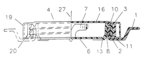
LIST OF DRAWING NUMBERS
Number Description
1 container cover 16 closure cap
2 cover opening rim 17 cap top
io 3 rim bead 18 cap seal projection
4 two piece threaded closure19 cap lugs
5 closure body 20 cap outer wall
6 body pull out diaphragm 21 cap thread
7 diaphragm pull ring 22 sealing recess
is 8 body inner wall 23 container
9 body inner rim 24 container neck
ring
body top wall 25 thread face
11 body outer wall 25(a) lower face
12 body thread 25(b) upper face
13 frangible web 26 body outer
rim
14 annular body recess 27 central axis
15 annular rim recess
DESCRIPTION OF THE INVENTION
Like parts shall be given like numbers throughout the figures.
Figure 1 illustrates a two piece threaded closure 4 before installation on
container cover 1. The closure 4 generally comprises a closure body 5 made of
soft
3o flexible plastic (i.e. low density polyethylene (LDPE)) or the like, and a
closure cap
16, made of semi-rigid plastic (for example high density polyethylene (HDPE))
or
~.~:<.-.::
l,Aj2 01 2004" ~A020ih905, '
~ CA 02470130 2004-06-10
Jan-12-a4 11:5aam Frnm-MILLER THOMTpN ~ + T-05~ P.14118 F-B95
s
the Irke. The body 5 and cap 96 are co-axially disposed about central axis 21'
and
secured in threaded assembly by, body thread 12 and cep thread 21.
A variety of thread types can be used in this invention. In one embodiment
s buttress.thread5 have been favorably used as shown providing a strong fit. .
t=urtherrnore there is a small gap which rn one example can be in the order of
up to
.100 of an inch between the outer lip of the buttress threads and the body
outer wall
'11 and top outer wall 20 respectively, which accommodates any ovality of the
annular shape of the body outer wall 11 and cap outer wall 2Q so as tv
facilitate the
so treading and unthreading of the closure cap 18 tv closure body 5, and
minimize
>'inaing of the parts.
Furthermore the buttress threads each present a telativeiy wide thread face
25 for strong threaded engagement therebetween. More specifically the body
outer
t 5 . wail 11 preserats buttress threads having a relatively wide Lower face
25(a) while the
cap outer watt 20 prevents buttress threads having a relatively wide upper
face
25(bj.
As rs shown in greater detail in Figure 9, closure body 5 is comprised of a
2o body pull out diaphragm 6 attached to a diaphragm Full ring T. ,rhe
diaphragy~ 5 is
attached by an annular frangible web 13 to the annular body inner wall 8. The
inner
. wall 8 is generally cylindrical in shape and terminates in body inner rim 9.
A body
top wall 10 beginning near body inner rim 9' extends generally radially
outward from
the body inner wall 8, and leads t4 body outer wall 11. Outer wall 11 is
cylindrical in
2s shape, and lies rapially outside of body inner wall 8. The inner wall 8,
top wall 10, ~ 'w
and body outer wall,l1, together form an annular body recess 94 on one side of
the
body top wall 10 and an annular nrn recess 15 so as to facilitate the treading
and
unthreading of the closure cap 16 to closure body 5, and minimize binding of
the
parts, sized to attach to the container cover 1.
IAI~~NDE~ SH~~T
Empf .zel t: l~/O1/~004 17:50 ' ,..". ...~. . . ,~rnw'i°:r ~r :::769
P.~14
F ~12~ 01 200~~ 4 '=CA02~f1905
' ~ ~ CA 02470130 2004-06-10 ~ ~~~.~-. ~:.~t, ",z.. :.i
Jan-1Z-o4 11:51am . Frnm-MILLER THOMSON + T-a5a P.15/18 F-885
9
Figure 2 is a side and cross-sectional view of the two piece threaded closure
after installation on container cover 1. The container 1 presents a cover
opening rim
2 having a generally upstanding peripheral sage with a rim bead 3 adapted to
be
received or captured by the annular rim recess 15 m a manner to be more fully
" ~ described herein. As shown in Frg. 2 the rim bead 3 is outwardly bulbous
in one
embodiment of the invention.
As shown in greater detail in Frg. 9 the generally cylindrical inner watt 8
braces agarnst cover opening rrm 2 and body top wall 10 overlies rim bead 3.
lU During installation, the body outer war) 11 expands generally radiailY
outwardly (i.e.
the diameter expands) as rim bead 3 passes along body annular recess 1~ and
into
the annual rim recess to be captured therein. After installation, the.body
outer wall
11 relaxes tv a smaller diameter and underlies rim bead 3. The cap outer wall
20
overlies and braces the body outer wall 11. against rim,bead 3 to further
resist
~s removal of closure 4 from container cover 1.
Figure 3 specifically shows the body inner rim 9, body top wall 1ti and body
outer rim defining a notch or sealing recess 22 which is adapted tv receive
cap seal
projection 18 when the cap 16 is threaded tv the closure body 5. As the cap 17
is
20 thr°aded to t he Nody 5 thG relatirreiy soft plastic of body 5
"gives'' and creates a
substantially tight seal, which seals quickly, rather than gradually, and acts
as a
gasket.
Figure 4 rs a top view of the closure body 5. Pull ring T is used to remove
pull
?3 out diaphragm 6,
Figure 5 is a side and crass-sectional view of the clvsvre cap 16 having top
17.
3o Figure 6 is a top view of the closure cap 16. A plurality of cap lugs 19
are
used as finger grips to assist the installation and removal of cap 16. Cap
seal
r/~I~~~N.D,~D SHAFT',
Empf.zeit:1~I01~~004 17:50 ~ ~ ~-~ ~~~~w-;'.r~~~~760 P.015
X12 flj-2004. ~ . CAC3201905f~
,.....
' ' CA 02470130 2004-06-10 . _. ,,..
Jan-12-04 11:51am Fresm-MILLER THOMSON * . T-050 P.18/1B F-BB5
9
projection 18 is designed to engage with body inner rim. and body outer rim ~6
to
create a seal. .
Figure 7 is a side and doss-sectronat view of the opening in a typical
container cover '1. A corer opening rim 2 which is generally cylindrical in
shape
ter,"~inates in a rim bead 3.
Frgure 8 is a side and cross-sectional view of an options! container 3 wrth
necl~ ring, 2 and rirn bead 3. An annular container nec[c ring 24 may be used
to
iu support the container 23 during the installation ~af closure 4.
Figure 9 is a detail side and cross-sectional view of the two piece threaded
closure after installation on container cover'1.
The assembly shown creates a low profile closure, resisting dislodgment
when accidentally struck. Moreover the seal and closure is stronger and more
robust. . ~ .
Various embodiments of the invention have now been describes! in detail.
2o Since changes in andlor.addrtions to the above-described best mode rx~ay be
r~,,ade
without departing from the nature, or scope of the invention, the invention is
not to
be limited to said details.
V
~~M~NDED SH-EE~T'
EmPf .zei t :1/01/2004 17:50 ~ - ~ - ~~~~ ,~~,~,- , ~:~ ~, ~ ..769 P .01E