Language selection

Search

Patent 2470340 Summary

Third-party information liability

Some of the information on this Web page has been provided by external sources. The Government of Canada is not responsible for the accuracy, reliability or currency of the information supplied by external sources. Users wishing to rely upon this information should consult directly with the source of the information. Content provided by external sources is not subject to official languages, privacy and accessibility requirements.

Claims and Abstract availability

Any discrepancies in the text and image of the Claims and Abstract are due to differing posting times. Text of the Claims and Abstract are posted:

  • At the time the application is open to public inspection;
  • At the time of issue of the patent (grant).
(12) Patent Application: (11) CA 2470340
(54) English Title: METHOD AND DEVICE FOR TRANSPORTING A FLOWABLE BUILDING MATERIAL
(54) French Title: PROCEDE ET DISPOSITIF DE TRANSPORT DE MATERIAUX DE CONSTRUCTION COULANTS
Status: Dead
Bibliographic Data
(51) International Patent Classification (IPC):
  • F04D 3/02 (2006.01)
  • F16L 53/32 (2018.01)
  • E01C 19/17 (2006.01)
  • F04D 7/06 (2006.01)
  • F04D 29/58 (2006.01)
  • F16L 11/12 (2006.01)
(72) Inventors :
  • TREFFERT, SVEN (Germany)
(73) Owners :
  • LEUTERT, HERBERT (Not Available)
  • TREFFERT, SVEN (Not Available)
(71) Applicants :
  • LEUTERT, HERBERT (Germany)
  • TREFFERT, SVEN (Germany)
(74) Agent: GOWLING WLG (CANADA) LLP
(74) Associate agent:
(45) Issued:
(86) PCT Filing Date: 2002-12-13
(87) Open to Public Inspection: 2003-06-26
Availability of licence: N/A
(25) Language of filing: English

Patent Cooperation Treaty (PCT): Yes
(86) PCT Filing Number: PCT/EP2002/014204
(87) International Publication Number: WO2003/052274
(85) National Entry: 2004-06-16

(30) Application Priority Data:
Application No. Country/Territory Date
01129925.2 European Patent Office (EPO) 2001-12-16
202 07 274.6 Germany 2002-05-03

Abstracts

English Abstract


The invention relates to a method and a device (10) for transporting flowable
building material in a heated state. According to the invention, a pump (12)
and a pipe (14) connected to said pump (12) are provided. The pump (12) and
the pipe (14) can be heated by at least one heating device (28).


French Abstract

Procédé et dispositif (10) de transport de matériaux de construction coulants à l'état chauffé. Ledit dispositif comporte une pompe (12) et une conduite (14) raccordée à cette pompe (12). La pompe (12) et la conduite (14) peuvent être chauffées à l'aide d'au moins un dispositif de chauffe (28).

Claims

Note: Claims are shown in the official language in which they were submitted.


Claims
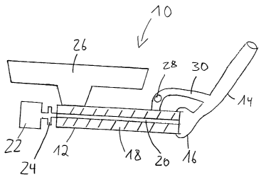
1. Process for conveying construction materials which
are flowable in the heated state by means of a pump (12,
42, 90, 110, 130, 152) and a pipe (14, 70, 80, 154)
connected to this pump (12, 42, 90, 110, 130, 152),
wherein the pump (12, 42, 90, 110, 130, 152) and the pipe
(14, 70, 80, 154) are heated.
2. Process according to claim 1, wherein a common
heating device or heating apparatus (28, 95, 116) is
provided for heating the pump (12, 42, 90, 110, 130, 152)
and the pipe (14, 70, 80, 154).
3. Process according to claim 2, wherein the common
heating device (28, 95, 116) is a bar-type burner with
which the pump (12, 42, 90, 110, 130, 152) is heated to
begin with and the pipe (14, 70, 80, 154) is heated with
the exhaust air produced during the heating of the pump
(12, 42, 90, 110, 130, 152).
4. Process according to one of claims 1 to 3, wherein
gaseous and/or liquid heat carriers are used to heat the
pump (12, 42, 90, 110, 130, 152) and the pipe (14, 70,
80, 154).
5. Process according to claim 4, wherein the heat
carriers are passed through heating channels (76) for the
heating.
6. Apparatus for conveying construction materials which
are flowable in the heated state by means of a pump (12,


2
42, 90, 110, 130, 152) and a pipe (14, 70, 80, 154)
connected to this pump (12, 42, 90, 110, 130, 152),
wherein at least one heating device (28, 95, 116) is
provided for heating the pump (12, 42, 90, 110, 130, 152)
and the pipe (14, 70, 80, 154).
7. Apparatus according to claim 6, wherein a common
heating device (28, 95, 116) is provided for heating the
pump (12, 42, 90, 110, 130, 152) and the pipe (14, 70,
80, 154).
8. Pump for conveying construction materials which are
flowable in the heated state, wherein a heating device
(28, 95, 116) is provided for the heating.
9. Pump according to claim 8, wherein heating channels
(76) are provided for heating the construction materials
which are to be conveyed by means of the pump (12, 42,
90, 110, 130, 152).
10. Pump according to claim 8 or 9, which builds up the
pressure needed to convey the construction materials by
means of a worm conveyor (20, 52, 94, 114).
11. Pump according to claim 10, wherein the worm
conveyor (20, 52, 94, 114) is constructed so that a heat
carrier can be passed through it.
12. Pump according to claim 10 or 11, wherein the worm
conveyor (20, 52, 94, 114) converges conically at one of
its ends.
13. Pump according to one of claims 10 to 12, which
comprises an inner tube (132) and an outer tube (134).


3
14. Pipe for conveying construction materials which are
flowable in the heated state, wherein a heating device
(28, 95, 116) is provided for the heating.
15. Pipe according to pipe 14, wherein heating channels
(76) are provided surrounding the pipe (14, 70, 80, 154).
16. Pipe according to claim 14 or 15 made up of sections
which are connectable to one another and adapted to be
heated separately.
17. Use of an apparatus (10, 40, 150) (28, 95, 116)
according to claim 6 or 7 for conveying construction
materials which are flowable in the heated state.

Description

Note: Descriptions are shown in the official language in which they were submitted.


CA 02470340 2004-06-16
Herbert Leutert et al. 301 001 P-WO
74538 Rosengarten 15.06.2004/jr/md
Method and device for transporting a flowable building
material
The invention relates to a process and an apparatus for
conveying construction materials which are flowable in
their heated state. The invention also relates to a pump
and a pipe for carrying out the process according to the
invention.
In the construction industry a plurality of building
materials are used which can basically be divided into
natural and artificial building materials. In the
construction of apartment buildings, in particular,
asphalt or pourable asphalt is used as a flooring
compound as it is non-flammable and provides good
soundproofing. Pourable asphalt is a mixture and
consists of about 8 to 10 % bitumen and about 90 to 92
minerals with a particle size of 5 to 11 mm.
A disadvantage of pourable asphalt is that it has to be
used in a liquid or flowable state and for this it has to
be at a temperature of about 250°C. The hot pourable
asphalt mass therefore has to be conveyed to the building
site as quickly as possible in asphalt boilers and then
has to be taken directly to the place of installation in
the building without the compound cooling too much.
Currently, it is predominantly transported around the
building site in wooden vessels such as wooden buckets or
wooden crates as transporting units. These are usually
carried to the place of use by means of a carrying yoke.
In addition, sloping hoists with suitable platforms are


CA 02470340 2004-06-16
2
used to convey the wooden units to the particular window
of the building under construction. However, for a
considerable part of the distance the wooden containers
have to be carried by hand. This is very time-consuming
and strenuous, as the person responsible has to carry the
heavy, hot wooden container to the place of installation
quickly before the asphalt contained therein has cooled
down too much.
In the light of this, a process for conveying
construction materials which are flowable in the heated
state is proposed wherein a pump and a pipe connected to
this pump are provided, and the pump and the pipe are
heated.
The pump is preferably provided in the vicinity of the
container in which the supply of hot asphalt is kept and
conveys it directly to the place of use through the pipe
connected thereto. If the asphalt is delivered by lorry
it is possible to drive the lorry right up to the pump
or, in the case of a mobile pump, to move the latter to
the lorry and connect it up.
As both the pump and the pipe are heated, it is possible
to prevent the asphalt or the construction material being
conveyed from cooling down too much. The construction
material is thus taken directly to the place of use in a
workable state.
Tests have shown that good results can be achieved with
pipe lengths of up to 50 m and over a height of up to 30
m. However, the process according to the invention can
also be used with longer pipes and bridging greater
differences in height. The power of the pump, which is
able to both pump out and suck in, simply has to be
matched to the length of the pipe.


CA 02470340 2004-06-16
3
At certain times, preferably at the end of a working day,
it must be ensured that the pump and conveying pipe are
cleaned. This can be done, for example, using a suitable
cleaning fluid and/or a cleaning object, such as a ball,
for example, a so-called scraper, which can be forced or
sucked through the pipe by pump action or by air
pressure.
Advantageously, a common heater is provided for heating
the pump and the pipe. The heater used may be, for
example, a bar burner which initially heats the pump.
The exhaust air formed as the pump is heated is used to
heat the pipe.
Preferably, gaseous and/or liquid heat carriers are used
to heat the pump and the pipe. These heat carriers are
usually passed through heating channels which surround
the pipe and the pump. Another possibility is to heat
the pump and/or pipe electrically, e.g. using electric
heaters. If electric heaters are used, a unit for
controlling or regulating the temperature is preferably
provided.
With the process according to the invention it is
possible to maintain flowable construction materials at a
substantially constant temperature and even to convey
these materials upwards.
The apparatus according to the invention for conveying
construction materials which are flowable in the heated
state comprises a pump and a pipe connected to this pump.
The pump and the hose are heatable by means of at least
one preferably electrically operated heater.


CA 02470340 2004-06-16
4
The pipe used may be a tube or a hose, e.g. made of a
flexible heat-resistant material. When choosing the
material it is important to note that it has to withstand
temperatures of from 220° C to 300° C. A special steel
alloy may also be used as the material.
It is advantageous to use a common heater to heat both
the pump and the pipe. In one embodiment of the
apparatus according to the invention this common heating
apparatus is a bar-type burner which is used initially to
heat the pump while the pipe is heated by the exhaust air
produced on heating the pump.
Preferably, electrical heaters are provided for heating
the apparatus according to the invention.
The pump according to the invention serves to deliver
materials which are flowable in the heated state, and can
be heated by a heater. Heating channels are preferably
provided for this purpose. These heating channels ensure
that the construction material contained in the pump does
not cool off too much. It may optionally be necessary to
pre-heat the pump before filling it with the construction
material which is to be conveyed. The pump can be used
to pump the construction material into the pipe provided
or to suck up material contained in the pipe.
According to one embodiment of the invention the pump
builds up the pressure needed for conveying the
construction materials with a worm conveyor and is thus a
so-called worm conveyor pump which usually has an endless
worm or screw conveyor cut into a cylindrical shaft, the
worm conveyor being used to transport flowable materials.
The worm conveyor may be directly heatable, i.e. by
passing a heat carrier through the worm conveyor, for


CA 02470340 2004-06-16
example, or the latter may contain an electrical heating
element. Alternatively, electrical heating elements or
heat carrier lines may run in or over the walls of the
pump.
5
In an alternative embodiment the necessary pressure is
built up by a piston or a stopper, while the stopper or
piston may be adapted to be forced right through the
pipe.
Advantageously the worm conveyor according to the
invention converges conically or tapers at one of its
ends, specifically at the end which is to be connected to
the pipe during use, this connecting end being matched in
diameter to the attached pipe.
The pump according to the invention preferably comprises
an inner pipe and an outer pipe which contains it, the
worm conveyor being mounted in the inner pipe and heating
elements being accommodated in or on the outer pipe.
This ensures easier access to the pump for maintenance.
The pipe according to the invention can also be heated by
means of a heater provided for this purpose. Heating
channels may be provided, surrounding the pipe. The heat
carrier provided is then passed through these channels,
for example, ensuring that the construction material
contained in the pipe does not cool down.
The heating channels are preferably applied in a spiral
around the pipe, as is necessary for mobility or
flexibility in a pipe made of a flexible material, e.g. a
hose. If for example the pipe is in the form of a spiral
hose, heating elements, e.g. electric heat conductors,
may be provided extending in a similar configuration to


CA 02470340 2004-06-16
6
the hose. This results in a smaller radius of bending of
the hose.
According to one feature of the invention an end cap is
provided on the pipe for the removal of exhaust air. A
regulator which regulates the speed of the pump during
delivery and intake may also be provided in the end cap.
Preferably, the pipe is enclosed in an insulating layer.
The heating elements are then located between the pipe
wall and the insulating layer.
A protective layer protects against mechanical influences
and may provide additional insulation.
According to one feature of the pipe according to the
invention it is made up of sections which can be
connected to one another. These sections are preferably
to be heated separately. Expediently, each section has a
temperature sensor, e.g. a PT-100, which detects the
temperature in this section. A preferably central
regulating device, optionally connected via a bus system,
then allows simultaneous or parallel temperature
regulation for each of the sections.
The sections may be from 1 to 10 m long, for example.
The pipe according to the invention preferably has an
inner and an outer hose or an inner and an outer tube.
The inner hose is expediently constructed as a corrugated
or spiral hose made of stainless steel. The outer hose
acts as insulation. In addition, it may be enveloped in
a protective jacket.


CA 02470340 2004-06-16
7
Between the inner and outer hoses are typically found the
heating pipes or heating elements. A temperature sensor
rests directly on the inner hose.
The use according to the invention envisages the use of
the apparatus according to the invention for conveying
flowable construction materials such as pourable asphalt,
for example.
Further advantages and embodiments of the invention will
become apparent from the specification and the
accompanying drawings.
It will be understood that the features mentioned above
and those still to be described hereinafter may be used
not only in the particular combination specified but also
in other combinations or on their own, without departing
from the scope of the present invention.
The invention is illustrated in the drawings by means of
exemplifying embodiments and is hereinafter explained
more fully with reference to the drawings.
Figure 1 shows a preferred embodiment of the apparatus
according to the invention in diagrammatic
representation,
Figure 2 shows another preferred embodiment of the
apparatus according to the invention,
Figure 3 shows a preferred embodiment of the pipe
according to the invention in cross section,
Figure 4 shows a detail of a pipe according to the
invention,


CA 02470340 2004-06-16
8
Figure 5 shows a preferred embodiment of the pump
according to the invention in diagrammatic
representation,
Figure 6 shows another preferred embodiment of the pump
according to the invention,
Figure 7 shows a detail of another preferred embodiment
of a pump according to the invention,
Figure 8 shows another preferred embodiment of the
apparatus according to the invention.
In Figure 1, a preferred embodiment of the apparatus
according to the invention is diagrammatically shown,
generally designated 10. The drawing shows a pump 12 and
a pipe 14 connected to the pump 12 via a connector 16.
The pump 12 is constructed as a worm conveyor pump 12
with a cylindrical shaft 18 and a worm conveyor 20 or
screw conveyor 20 rotatably mounted therein. The worm
conveyor 20 is driven by a drive motor 22, or by an
electric motor, via a bearing block 24, i.e. rotated
about its longitudinal axis. The material to be conveyed
is introduced into the pump 12 through a hopper or funnel
26 and from there is forced towards the connector 16 and
the pipe 14 by the rotation of the worm conveyor 20. The
pipe 14 ends at the place where the material or
construction material is to be worked, which means that
the material no longer has to be transported manually.
In order to allow this to happen with a construction
material which has to be heated up, in the apparatus 10
shown there is a heater 28 which heats both the pump 12
and also the pipe 14 via a feed line 30. This is
preferably done by means of a heat carrier which supplies


CA 02470340 2004-06-16
9
the heat generated by the heater 28 to the pump 12 and
the pipe 14.
Usually, the pump 12 is heated first and the exhaust air
produced is used to heat the pipe 14 via the feed line
30.
Figure 2 shows another embodiment of the apparatus
according to the invention. The apparatus 40 has a pump
42 of mobile construction, i.e. it can be moved along on
a wheel 44 or wheels 44 to a tank 46. The mobile pump
station 42 is connectable to a pipe (not shown) via a
connector 48.
The pump 42 comprises an elongated cylindrical shaft 50
and a worm conveyor 52 located therein which is to be
driven by a motor 54 via a bearing block 56. In the
embodiment shown the motor 54 and the bearing block 56
are movable together with the pump 42. However, it is
certainly possible for only the pump 42 to be mobile and
for the motor 54 andjor the bearing block to be fixedly
mounted in one place.
The construction material contained in the tank 46 is let
into the pump 42 through a supply line 58 and an
actuating device 60. The actuating device 60 initiates or
controls this process. The supply line 58 may also be
heatable.
Figure 3 shows a cross section through an advantageous
embodiment of a pipe according to the invention which is
designated 70. A wall 72 defines the cross sectional
area of the pipe 70 through which the typically viscous
material to be conveyed is pumped. The wall 72 is
surrounded by a heating jacket 74 which is in turn made
up of four heating channels 76 which totally surround the


CA 02470340 2004-06-16
wall 72. A heat carrier or heating medium is conveyed
through these heating channels 76 which preferably run in
a spiral. The heat carrier may be, for example, air, oil,
particularly thermal oil, or water.
5
The pipe 70 is surrounded by an insulating layer 78 which
ensures that the heat energy is not excessively given off
to the surroundings.
10 In the embodiment shown the heating jacket 74 is wrapped
around the wall 72 of the pipe 70. However, it is also
thoroughly possible for heating pipes to be provided
already in the wall 72 of the pipe 70, through which the
heat carrier is conveyed. Another possibility is to
provide electrical heating elements in or on the wall 72
of the pipe 70.
Figure 4 shows a detail of a pipe 80, specifically the
end portion. The Figure shows a heating jacket 82, in
which heating channels are provided, surrounding the pipe
80. A handle 84 allows a workman to bring the end of the
pipe directly to the place of use. This handle 84 is
hollow so that the exhaust air can be recycled back
through an exhaust pipe 88, as shown by arrows 86. A
sealed system can thus be produced.
Figure 5 shows a pump 90, namely a worm conveyor pump 90.
This is made up of a shaft 92 and a worm conveyor 94. A
heater 95 is also shown. Underneath the pump 90 and
along it runs a heating element 96 actuated by the heater
95 which ensures that the pump 90 can be heated over its
entire length.
The worm conveyor 94 comprises a shaft 98 and blades 100
mounted on the shaft 98. The shaft 98 which defines the
longitudinal axis of the worm conveyor 94 may be of


CA 02470340 2004-06-16
11
hollow construction so that a heat carrier can be passed
through it and in this way the worm conveyor 94 can be
heated directly. According to another alternative, an
electrical heating element is provided in the shaft 98.
A heating element of this kind may of course also be
installed in or on the wall of the shaft 92.
Figure 6 shows another pump 110 which again is made up of
a shaft 112 and a worm conveyor 114. Alternatively to
the worm conveyor pump 110 shown here, a vane pump may
also be used in the apparatus according to the invention.
Figure 6 also shows a heating apparatus 116 which is
connected to a heating jacket 118. This heating jacket
completely surrounds the shaft 112 of the pump 110.
Heating channels may in turn be provided in the heating
jacket 118.
The pump (110) is safely heated in this way. The exhaust
air produced can be fed through a feed line 120 into a
pipe (not shown).
Figure 7 shows a detail of another pump according to the
invention, generally designated 130. It can be seen that
this pump 130 comprises an inner tube 132 and an outer
tube 134, the inner tube 132 being received within the
outer tube 134.
In the inner tube 132 is mounted a worm conveyor 136 for
conveying pourable asphalt contained in the pump.
In or on the walls of the outer tube 134 are heating
elements 138, in this case electrical heating elements
138, which enable the pourable asphalt contained in the
pump to be maintained at a constant temperature. This


CA 02470340 2004-06-16
12
temperature is monitored by a temperature sensor 140,
e.g. a PT-100.
Figure 8 diagrammatically shows another apparatus 150
according to the invention. It comprises a pump 152 and
a pipe 154 connected thereto.
It can be clearly seen that the pump 152, in this case a
worm conveyor pump, converges conically towards one of
its ends. This conically convergent end 156 serves for
connection to the pipe 154. The worm conveyor in the
pump 152 may be shaped accordingly.
The pipe 154 comprises an inner hose 158 and an outer
hose 160. Between these two are provided heating
elements 162 which are preferably arranged close to the
inner hose 158.
Directly mounted on the inner hose 158 is a temperature
sensor 164 which can be used to monitor and regulate the
temperature in the inner hose 158 and hence the
temperature of the construction material conveyed.
There are various possible ways of heating the pump
according to the invention and the pipe according to the
invention. The procedures illustrated are only a
selection and obviously may be combined with one another
in any desired manner.

Representative Drawing
A single figure which represents the drawing illustrating the invention.
Administrative Status

For a clearer understanding of the status of the application/patent presented on this page, the site Disclaimer , as well as the definitions for Patent , Administrative Status , Maintenance Fee  and Payment History  should be consulted.

Administrative Status

Title Date
Forecasted Issue Date Unavailable
(86) PCT Filing Date 2002-12-13
(87) PCT Publication Date 2003-06-26
(85) National Entry 2004-06-16
Dead Application 2007-12-13

Abandonment History

Abandonment Date Reason Reinstatement Date
2006-12-13 FAILURE TO PAY APPLICATION MAINTENANCE FEE

Payment History

Fee Type Anniversary Year Due Date Amount Paid Paid Date
Application Fee $200.00 2004-06-16
Maintenance Fee - Application - New Act 2 2004-12-13 $50.00 2004-11-19
Registration of a document - section 124 $100.00 2005-01-04
Maintenance Fee - Application - New Act 3 2005-12-13 $50.00 2005-12-07
Owners on Record

Note: Records showing the ownership history in alphabetical order.

Current Owners on Record
LEUTERT, HERBERT
TREFFERT, SVEN
Past Owners on Record
None
Past Owners that do not appear in the "Owners on Record" listing will appear in other documentation within the application.
Documents

To view selected files, please enter reCAPTCHA code :


To view images, click a link in the Document Description column. To download the documents, select one or more checkboxes in the first column and then click the "Download Selected in PDF format (Zip Archive)" or the "Download Selected as Single PDF" button.

List of published and non-published patent-specific documents on the CPD .

If you have any difficulty accessing content, you can call the Client Service Centre at 1-866-997-1936 or send them an e-mail at CIPO Client Service Centre.


Document
Description 
Date
(yyyy-mm-dd) 
Number of pages   Size of Image (KB) 
Cover Page 2004-09-03 1 34
Abstract 2004-06-16 2 70
Description 2004-06-16 12 439
Representative Drawing 2004-06-16 1 6
Claims 2004-06-16 3 75
Drawings 2004-06-16 4 51
Assignment 2004-06-16 3 87
PCT 2004-06-16 5 206
Correspondence 2004-08-31 1 27
Correspondence 2004-10-01 1 29
Fees 2004-11-19 1 31
Assignment 2005-01-04 4 114
Fees 2005-12-07 2 87