Note: Descriptions are shown in the official language in which they were submitted.
CA 02471062 2004-06-16
SELF-PROPELLED HARVESTING MACHINE
Field of the Invention
The invention concerns a self-propelled harvesting machine with a chassis,
to which rolling support devices in contact with the ground are attached,
which are
arranged for the forward propulsion and the steering of the harvesting machine
and
of which the front set of rolling support devices are arranged ahead of the
rear rolling
support devices in the direction of operation.
Back round of the Invention
In self-propelled harvesting machines, the load on the wheels and thereby
the compaction of the ground are, to a considerable degree, a function of the
weight
distribution of a front harvesting attachment mounted on the machine and a
possible
trailer load. In the state of the art, the rear of the machine is ballasted as
a function
of the type of the front harvesting attachment. Therefore, with relatively
heavy front
harvesting attachments, a relatively heavy rear ballast must be mounted in
order to
assure a safe operating performance of the harvesting machine by providing an
adequate load on the steerable rear wheels. These measures considerably
increase
the weight of the harvesting machine, which contributes to the disadvantage of
the
compaction of the ground. Furthermore, upon a change in the front harvesting
attachment, the rear ballast must be changed to conform which results in a not
inconsiderable cost in time.
DE 100 04 622 A and AT 285 439 A describe ground level conveyor
vehicles with an adjustable wheel base that is used to provide greater
stability to the
vehicle particularly with higher lifting heights.
The problem underlying the invention is seen in the need to further develop
a self-propelled harvesting machine in such a way that the aforementioned
disadvantages do not occur or do so only to a lesser degree.
Summary of the Invention
According to the present invention, there is provided an improved ground
support arrangement for a self-propelled harvesting machine.
It is an object of the invention to provide a harvesting machine including
front and rear sets of rolling support devices arranged for the propulsion and
steering
of the vehicle and wherein at least one of the sets of rolling support devices
is
CA 02471062 2004-06-16
mounted for adjustment along the operating direction of the vehicle in order
to attain
an appropriate distribution of the weight of the machine on the front and rear
sets of
rolling support devices.
It is proposed that the spacing between the front and the rear sets of rolling
support devices in contact with the ground, which may be wheels or crawler
track
assemblies, be configured as variable by an appropriate arrangement at the
chassis
of the self-propelled harvesting machine. When wheels are used, the wheel base
can thereby be adjusted. As a rule, the front set of rolling support devices
are driven
and are rigidly connected to the chassis, while the position of the rear
rolling support
devices, as seen in the forward direction of operation, which are or is, as a
rule,
steerable, is changed relative to the chassis.
In this way, an accommodation to the weight of the front harvesting
attachment used at that time can be attained in each case by a variation of
the
wheelbase of the harvesting machine. The weight of the harvesting machine can
be
distributed over the front and the rear sets of rolling support devices in an
appropriate manner, so as to achieve a sufficiently heavy loading on the rear
rolling
support devices, that leads to a good steering ability. Simultaneously, the
load on
the front rolling support device is reduced, so that the compaction of the
ground is
lessened. The ballasting of the rear of the harvesting machine may possibly be
omitted completely, resulting in a reduction of the total weight of the
harvesting
machine. Moreover, the set-up time of the harvesting machine is shortened
considerably, so that its flexibility is increased.
Basically, it would be conceivable that the aforementioned spacing be
provided as input by an operator.. The disadvantage here is that inexperienced
operators, in particular, could bring about unfavorable operating
characteristics of the
harvesting machine by erroneous inputs. In a preferred embodiment, an
automatic
adjustment of the spacing between the front and the rear rolling support
devices in
contact with the ground is therefore preferred.
The spacing that is to be provided as input is primarily a function of the
weight of a front harvesting attachment and a trailer load if a trailer is
used. These
loads are therefore considered by the arrangement for the readjustment of the
2
CA 02471062 2004-06-16
spacing. The weight of the front harvesting attachment can be manually input
by an
operator, or detected by a sensor. The use of an electronic memory unit
associated
with the front harvesting attachment can also be used for the input of the
weight of
the front harvesting atfiachment. The memory unit may be located in a fixed
position
on the front harvesting attachment and transmit the data over a bus line to
the
arrangement for the readjustment of the spacing. Alternatively, a memory card
or
the like can be used that is inserted into an appropriate reading implement.
The
weight of a trailer load is detected analogously.
If the weight of the front harvesting attachment is to be detected by a
sensor, such a sensor can be arranged to measure the hydraulic pressure in the
hydraulic circuit of the lifting device of the front harvesting attachment.
But
measurement with a load cell at the suspension of the front harvesting
attachment
on the harvesting machine would also be conceivable. Analogously, the support
force of a trailer load is preferably detected by a sensor at the trailer
coupling.
It should be noted that it would also be conceivable to adjust the position of
the rolling ground support devices automatically or manually on the basis of
signals
from sensors, which detect the weight borne by the rolling support device on
the
ground.
A change in the spacing between the front and the rear sets of rolling
support devices in contact with the ground during the operation poses the
danger
that the operating and steering performance can change suddenly. An obvious
solution therefore is to provide the arrangement for the readjustment of the
spacing
with information as to the immediate speed of the harvesting machine, that can
be
detected, for example, by a speed sensor, in order to permit a change in the
spacing
only when the harvesting machine is stopped.
During operation on public roads, a number of requirements of the law must
be fulfilled, that can be met in many cases only when the spacing between the
front
and the rear sets of rolling support devices in contact with the ground is
maintained
at a certain value or in a certain range. On the other hand, on the field the
spacing
can be chosen at will. In a preferred embodiment, the arrangement for the
change in
the spacing between the front and the rear sets of support devices in contact
with the
3
CA 02471062 2004-06-16
ground can therefore be operated so as to bring the spacing to a certain
value, for
example, the maximum value, in case the machine is in a public road operating
mode.
The public road operating mode can be detected an the basis of the position
of a field/public road operating mode switch. Alternatively, or in addition,
the position
of an electronic selector switch or a mechanical selector lever for the gear
ratio of a
shifted gearbox of the operating drive of the harvesting machine can be
interrogated.
On the other hand, if the harvesting machine is on a field, the automatic
adjustment
of the spacing is performed as described above.
Brief Descri tion of the Drawings
The drawings show an embodiment of the invention that shall be described
in greater detail in the following.
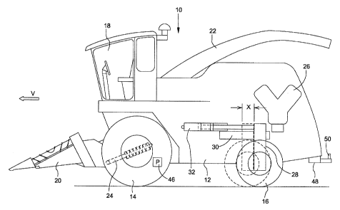
FIG. 1 is a left side elevational view of a self propelled harvesting machine.
FIG. 2 shows a schematic of a arrangement for changing the spacing
between the front and the rear roiling support devices in contact with the
ground of
the harvesting machine.
FIG. 3 shows a flow chart that illustrates the method of operation of the
arrangement.
Description of the Preferred Embodiment
The self-propelled harvesting machine 10 is depicted in the form of a self-
propelled forage harvester in FIG. 1 and is supported on a chassis 12 that is
carried
by a front rolling support device 14 in contact with the ground, in the form
of a pair of
wheels, and a rear rolling support device 16 in contact with the ground, in
the form of
a single wheel. The operation of the harvesting machine 10 is controlled by an
operator from an operator's cab 18 from which a front harvesting attachment 20
can
be controlled within the view of the operator. Besides its application to
forage
harvesters, the invention can be applied to any desired harvesting machine
such as,
for example, combines, grape harvesters, cotton harvesters or self-propelled
balers.
The front harvesting attachment 20 is attached to the harvesting machine 10
so as to be removable and can be exchanged for any desired front harvesting
4
CA 02471062 2004-06-16
attachment. Crop taken up from the ground by the front harvesting attachment
20,
for example, corn, grass or the like, is conveyed into the interior of the
harvesting
machine 10 by rough pressing rolls and conducted to a chopper drum that chops
it
into small pieces and delivers it to a conveyor arrangement. The crop leaves
the
harvesting machine 10 to an accompanying trailer over a rotating discharge
duct 22.
The front harvesting attachment 20 is connected in joints to the chassis 12 so
as to
pivot about the axis of rotation of the chopper drum. The pivoting, that is,
the input of
the height of the front end of the front harvesting attachment 20 is performed
by
means of a hydraulic cylinder 24 that extends between the front harvesting
attachment 20 and the chassis 12.
An internal combustion engine 26 is located in the rear region of the
harvesting machine 10 and supplies the driven elements of the machine 10 with
driving energy.
The front set of rolling support devices 14 in contact with the ground are
connected rigidly with the chassis 12, that is, they cannot be steered, and
can be
driven. Optionally, the rear rolling support 16 in contact with the ground is
fastened
to a suspension 28, whose position in the forward operating direction V in the
harvesting machine 10 is variable. For that purpose, the suspension 28 is
supported
in bearings, free to slide, on a horizontal guide 30 extending in the forward
operating
direction V and a hydraulic repositioning cylinder 32 extends between the
chassis 12
and the suspension 28. Thereby, the wheel base of the harvesting machine 10,
that
is, the spacing between the rolling support devices 14 and 16 in contact with
the
ground, can be varied by changing the length of the repositioning cylinder 32.
The
rear rolling support device 16 can be steered, that is, it can be rotated
about a
vertical axis, is fastened to the suspension 28 and provides the input of the
direction
of operation of the harvesting machine 10. For this purpose, a steering
cylinder (not
shown) is provided that is described, for example, by U.S. 4, 222, 452, whose
disclosure is incorporated in the present application by reference.
An advantage of the use of a single rear wheel lies in the fact that it is
offset
relative to the front wheels, which contributes to the reduction in the
compaction of
the ground, and in the smaller steering radius that can be achieved. However,
a
CA 02471062 2004-06-16
conventional rear axle with two steerable wheels could also be attached to the
harvesting machine 10. Then, the rear axle would be connected with the guide
30
and the repositioning cylinder 32 over the suspension 28.
The complete configuration of the arrangement 34 for the variation of the
spacing between the front and the rear sets of rolling support devices 14 and
16 is
shown schematically in FIG. 2. An electronic control arrangement 36 operating
analogously or digitally is connected electrically with a valve control
arrangement 38
that controls a proportional control valve 40 as a function of the current or
voltage or
a pulse-width modulated valve, or any other desired appropriate valve. The
proportional control valve 40 is connected with a hydraulic fluid pressure
source 42
and with the repositioning cylinder 32. A mechanical position detecting
arrangement
44, in the form of a linear potentiometer or any other desired sensor, mounted
between the chassis 12 and the suspension 28 provides the control arrangement
36
with information about the immediate position of the suspension 28. Hence, the
control arrangement 36 is arranged to control the spacing between the front
and rear
sets of rolling support devices 14 and 16 while using a feedback signal.
Moreover, the control arrangement 36 is connected with a front harvesting
attachment weight sensor 46 that is looped into the hydraulic circuit of the
hydraulic
cylinder 24 used to reposition the height of the front harvesting attachment
20. The
pressure of this hydraulic circuit contains information about the weight of
the front
harvesting attachment 20 since a higher pressure is required to lift a heavier
front.
harvesting attachment 20 than to lift a lighter front harvesting attachment
20. The
part number call-out 52 identifies an input arrangement that can be used as an
alternative, or in addition to, the front harvesting attachment weight sensor
46, that
permits the operator in the operator's cab 18 to provide as an input the type
or the
weight or the mass of the front harvesting attachment 20.
The control arrangement 36 also receives an input from a sensor 48 that
detects the support force of a trailer that is coupled to a coupling 50 at the
rear of the
harvesting machine 10. Alternatively, or in addition to the sensor' 48, an
input
arrangement can be used that permits the operator in the operator's cab 18 to
provide as an input the type, or the weight or the mass of a trailer at the
coupling 50.
6
CA 02471062 2004-06-16
A speed sensor 54 detects the actual forward propulsion velocity of the
harvesting machine 10. It can interact with one of the sets of rolling support
devices
14 and 16 or it may be a radar sensor, that interacts directly with the
ground.
Finally, the control arrangement 36 is connected with a gear ratio sensor 56
or a fieldlpublic roads operating mode switch 58. The gear ratio sensor 56
detects
the gear ratio of a gearbox of the operating drive of the harvesting machine
10
selected at a given time. The field/public roads operating mode switch 58 is
located
in the operator's cab 18 and is used by the operator to provide an input of
the
operating mode of the harvesting machine 10. In the public roads operating
mode,
all elements of the harvesting machine 10 required only for harvesting cannot
be
activated. Analogously, during operation on a field, only the elements
required for
harvesting can be turned on, while the elements required for operation on
public
roads are deactivated.
The manner of operating the arrangement is explained in the following on
the basis of the flow chart shown in FIG. 3.
After starting in step 100, that is performed after starting the harvesting
machine 10, the question is posed initially whether the forward propulsion
velocity of
the harvesting machine 10 is zero, that is, whether the signal of the speed
sensor 54
points to the fact that the machine is stopped. If it is not the case, step
102 again
follows. Therefore, a repositioning of the rear rolling support device 16 is
not
possible during this operation.
Otherwise, step 104 follows in which the gear ratio sensor 56 and/or the
fieldlpublic roads operating mode switch 58 is interrogated. If the gear ratio
sensor
56 determines that the gearbox of the operating drive of the harvesting
machine 10
is in its highest gear ratio, the information is taken from it that the
harvesting machine
is in the public roads operating mode, since this gear ratio is not used
during the
harvesting operation. On the basis of the field/public roads operating mode
switch
58, it is also possible to check whether the harvesting machine 10 is in a
harvesting
mode or not.
If it is not in a harvesting operation, step 106 follows, in which the
question is
posed whether the suspension 28 and the rear rolling support device 16 in
contact
7
CA 02471062 2004-06-16
with the ground are in a position for operation on public roads, as permitted
by the
public roads traffic authorities. If this is the case, step 102 again follows.
Otherwise,
step 108 follows in which the control arrangement 36 brings the rolling
support
device 16 into the aforementioned position for the operation on public roads
while
using the feedback signal of the position detection arrangement 44 and the
valve
control arrangement 38.
If the result in step 104 shows that the harvesting machine 10 is in a
harvesting operating mode, then step 110 follows. On the basis of the signals
of the
front harvesting attachment weight sensor 46 and of the sensor 48 for the
support
load on the coupling 50 and optionally the input arrangement 52, the
calculation is
made into which position the suspension 28 with the rear rolling support
device 16 in
contact with the ground is to be brought, in order to attain an appropriate
weight
distribution on the rolling support devices 14 and 16. This appropriate weight
distribution is characterized by the fact that a sufficient proportion of the
total weight
is absorbed by the rear rolling support device 16. Thereby, the compaction of
the
ground by the front set of rolling support devices 14 is reduced and the
result is a
good steering performance. Corresponding to the result of the calculation, the
position of the suspension 28 is varied. In addition, sensors could be used on
the
axles of the rolling support devices 14 and 16 in order to recheck the weight
distribution attained or to fine tune it. Step 110 is again followed by step
102.
FIG. 3 begins with the premise that the gear ratio of the gearbox of the
operating drive can be changed only when the machine is stopped, and that the
field/public roads operating mode switch 58 can be adjusted only when the
machine
is stopped. If these conditions do not apply, the chart in FIG. 3 must be
subjected to
appropriate modifications in order to prevent an undesired position of the
suspension
28 and the rear rolling support device 16 from being attained upon a change in
mode
of operation of the harvesting machine 10 during operation.
Having described the preferred embodiment, it will become apparent that
various modifications can be made without departing from the scope of the
invention
as defined in the accompanying claims.
8