Note: Descriptions are shown in the official language in which they were submitted.
CA 02471137 2004-06-18
WO 03/055960 PCT/US02/41036
COMPOSITION AND METHOD FOR IMPROVING OIL RECOVERY
BACKGROUND
Field
Methods and compositions for improving oil recovery from a reservoir, and
cleaning contaminated soil, objects, and wildlife.
Background Information
Crude oil or petroleum is a complex liquid mixture of hydrocarbons containing
primarily carbon, hydrogen, and varying amounts of other atoms such as sulfur,
nitrogen, oxygen, and others. Crude oil is recovered from subsurface oil
reservoirs,
wherein the oil is held within pores and voids of rock and sand, and then
refined to
produce a number of useful substances such as gasoline, lubricants and
chemical
building blocks.
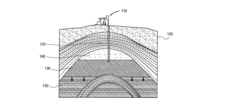
Figure 1 illustrates oil production well 110 recovering oil 130 from oil
reservoir 120. Production well 110 includes a production line 125 that extends
into a
volume of the oil held between gas 140 at a top surface and water 150 at a
bottom
surface. Production well 110 is able to recover the oil from sand and rock
that contains
it due to pumping action of the well and native pressure of the oil within the
reservoir.
Recovery of oil such as that shown in Figure 1 is comparatively easy when the
oil is light, has a low viscosity, the reservoir is full of oil, and the
reservoir has a high
pressure. However, recovery of the oil becomes more challenging when these
conditions are not met. For example, rather than light, the oil may be heavy
viscous oil
and/or the reservoir may be substantially depleted of oil so that the
reservoir pressure
has been reduced. In such situations, it may be more difficult to recover oil
from the
reservoir. This leaves much residual oil trapped within the reservoir as an
unrecoverable resource.
Figure 2 illustrates oil 230 wetting an outside surface of sand particles 210A-
C
and within two oil-filled pores 220A-B formed by the sand particles. Such oil
wetting
of sand may make substantial amounts of the reservoir oil difficult to recover
due to
strong attractions such as high surface tension forces and capillary forces
holding them
fixedly to such regions. It may be difficult to remove the oil from such
regions by
1
CA 02471137 2004-06-18
WO 03/055960 PCT/US02/41036
using pressure as the only driving force for removal. Additionally, when water
is
present external to the pores it may tend to hold the oil inside the pores.
Various enhanced oil recovery methods are known to improve oil recovery
from a reservoir. Figure 3 illustrates a steam flooding enhanced oil recover
operation
to improve oil recovery from a reservoir. Steam addition system 310 comprising
a
steam generator, a stack gas scrubber, piping, flow control elements, and a
steam
injection line is used to add or inject steam into oil reservoir 320. The
steam heats the
oil in the reservoir to reduce the viscosity of the oil and make it less
resistive to flow
(similarly to the way that honey or molasses flows better when heated). This
may
allow hot oil proximate sand particle surfaces and within pores to become
sufficiently
mobile relative to the sand that the oil can move toward oil production well
330 suction
inlet and be recovered from the reservoir at the wellhead.
There are several problems associated with steam flooding. A first problem is
channeling wherein steam added to the reservoir takes the path of least
resistance to the
oil production well by improving the recovery of the weakest attached and most
available oil first. Once a route to the oil production well has been
established further
steam flooding has decreased effectiveness due to the easy bypass to the low
pressure
oil production well. A second problem with steam flooding is that it is less
favorable
for deep oil reservoirs with high pressures. This is partly due to the
increased pressure
and heating needs to make the steam suitable for the high reservoir pressures.
Accordingly, there is a need for an improved approach for improving oil
recovery from a reservoir.
BRIEF DESCRIPTION OF THE DRAWINGS
The features, aspects, and advantages of the invention will become more
thoroughly apparent from the following detailed description, appended claims,
and
accompanying drawings in which:
Figure 1 illustrates an oil production well recovering oil from an oil
reservoir.
Figure 2 illustrates difficult to recover oil.
Figure 3 illustrates a steam flooding enhanced oil recover operation to
improve
oil recovery from a reservoir.
Figure 4 illustrates a process flow for adding a recovery composition to an
oil
reservoir and then removing oil from the reservoir.
2
CA 02471137 2004-06-18
WO 03/055960 PCT/US02/41036
Figure 5 illustrates a process flow for adding a recovery composition to a
production well and then removing oil through the well.
Figure 6 illustrates a process flow for adding a recovery composition to a
production well and using steam flooding.
Figure 7 illustrates a process flow for adding a recovery composition
according
to a cup tool method.
Figure 8 illustrates a process flow for adding a recovery composition to a
steam
well.
Figure 9 illustrates a schematic diagram for adding a recovery composition to
an injection well.
Figure 10 illustrates a schematic diagram of improved recovery of difficult to
recover oil with the use of a recovery composition.
Figure 11 illustrates a schematic top view of an exemplary oil reservoir field
that was treated by an oil recovery composition, the top view showing
positions of
injection wells and recovery wells control sample of oil recovered from a
control well
of the exemplary oil reservoir shown in Figure 11, the control sample not
affected by
the oil recovery composition injected into the oil reservoir.
Figure 12 illustrates exemplary gas chromatograph data for a sample of oil
taken from well R16 as a control sample.
Figure 13A illustrates exemplary gas chromatograph data determined for an oil
sample that was collected from well R1 of the oil reservoir shown in Figure
11.
Figure 13B illustrates exemplary gas chromatograph data determined for an oil
sample that was collected from well R2 of the oil reservoir shown in Figure
11.
Figure 13C illustrates exemplary gas chromatograph data determined for an oil
sample that was collected from well R3 of the oil reservoir shown in Figure
11.
Figure 13D illustrates exemplary gas chromatograph data determined for an oil
sample that was collected from well R4 of the oil reservoir shown in Figure
11.
Figure 13E illustrates exemplary gas chromatograph data determined for an oil
sample that was collected from well RS of the oil reservoir shown in Figure
11.
Figure 13F illustrates exemplary gas chromatograph data determined for an oil
sample that was collected from well R6 of the oil reservoir shown in Figure
11.
Figure 13G illustrates exemplary gas chromatograph data determined for an oil
sample that was collected from well R8 of the oil reservoir shown in Figure
11.
3
CA 02471137 2004-06-18
WO 03/055960 PCT/US02/41036
Figure 14 illustrates a system for washing oil-contaminated soil with an oil
recovery composition.
DETAILED DESCRIPTION
Terminolo~y
Before providing a detailed explanation of the claimed subject matter and
various exemplary embodiments thereof, some terms that will be used throughout
this
description are briefly defined as follows:
"Oil" refers to an arbitrarily complex organic liquid mixture of naturally
occurring hydrocarbon and other components having arbitrary and widely varying
properties such as viscosity, density, color, and composition.
"Reservoir" refers to a subsurface region that contains oil. The reservoir may
include a geologic formation or trap of oil wherein the oil is contained
within voids and
pores of sand, rock, shale, and similar structures. The reservoir may be a
terrestrial
reservoir or an off-shore reservoir.
"Viscosity" refers to an oil's resistance to flow.
"Density" refers to mass of oil per unit volume. Both viscosity and density
affect the ability to get oil to flow to a well bore of a production line and
the ability to
pump the oil within the line. A high viscosity, high density oil may be more
difficult to
recover than a low viscosity, low density oil partly because the oil may
become trapped
within voids in the reservoir and may be difficult to remove from these voids.
By way
of analogy, it is similarly more difficult to pour honey through a small
opening than it
would be to pour water through the same opening.
"Permeability" refers to the fluid transmitting measure of a sand or rock
material of a reservoir.
"Mobility" refers to the ratio of permeability to viscosity.
Additionally, unless indicated otherwise percentages for compositions are
percentage by volume. For example, a composition having 95 percent (%) fatty
acid
alkyl ester may have 95 gallons of fatty acid alkyl ester for every 100
gallons of the
composition.
4
CA 02471137 2004-06-18
WO 03/055960 PCT/US02/41036
Oil Recover~ompositions
In one embodiment, a recovery composition is described. The recovery
composition is suitable for introduction into a reservoir to improve the
recovery of oil
contained within the reservoir. In one embodiment, the recovery composition
comprises at least one type of fatty acid alkyl ester. The recovery
composition may
contain a blend of different fatty acid alkyl esters. In the case of a blend,
the different
types of fatty acid alkyl esters may be in any proportion that is desired for
the particular
implementation.
Suitable fatty acid alkyl esters for a recovery composition may be represented
by the general formula R'COOR wherein R' and R are typically different
hydrocarbon
groups containing carbon and hydrogen and potentially other components. For
example, the groups may contain heteroatoms such as nitrogen, oxygen, sulfur,
and
others that may be found in organic compounds. The fatty acid alkyl ester may
be an
ester derived from a triglyceride. For example, the fatty acid alkyl ester may
be a
vegetable oil lower alkyl ester. The term "lower alkyl ester" refers to an
alkyl ester
having an R-group of between 1 and 5 carbons inclusive and preferably between
1 and
2 carbons inclusive. This may include such R-groups as methyl, ethyl, n-
propyl,
isopropyl, n-butyl, n-pentyl, and isopentyl. Preferably the R-group contains 1
or 2
carbons. For example, the fatty acid alkyl ester may comprise a soy methyl
ester or a
soy ethyl ester. The R'-group may comprise a carbon chain having between 4 and
22
carbons. In one embodiment, the fatty acid alkyl ester is a "long-chain fatty
acid alkyl
ester" having an R'-group with between 12 and 20 carbons inclusive and
preferably
between 16 carbons or 18 carbons inclusive. The carbon chain may be saturated
and
contain no double bonds or be unsaturated and contain one or more double
bonds. The
fatty acid alkyl ester may comprise a mixture of sixteen carbon chain length
methyl
esters, seventeen carbon chain length methyl esters, and eighteen carbon chain
length
methyl esters. For example, the mixture may comprise a linoleic acid methyl
ester, an
oleic acid methyl ester, a stearic acid methyl ester, and a palmitic acid
methyl ester.
Synthesis Of Fatty Acid Alkyl Esters By Trans-esterification Of Triglvcerides
One method for creating a fatty acid alkyl ester suitable for use in a
recovery
composition is trans-esterification of a plant or animal triglyceride.
Triglycerides are
oils or lipids that occur naturally in plants and animals. The triglycerides
are esters
CA 02471137 2004-06-18
WO 03/055960 PCT/US02/41036
generally characterized by having three molecules of fatty acids linked to
glycerol.
Different types of triglycerides are contemplated including those present in
natural oils
of plants, vegetables, corn, spent French-fry oil, olive, palm, coconut,
oleaginous seeds,
soybean, rapeseed, sunflower, canola, safflower, animals, animal tallow,
butter, milk,
and others. Table 1 shows approximate fatty acid concentrations in
triglycerides from
exemplary plant and animal sources.
Table 1. Fattv Acids In Naturally Occurring Substances
TriglycerideLaurica & Palmitic' Stearicd Oleic' Linoleic~
Source Myristicb
Coconut74 10 2 7 -
Corn - 8-12 3-4 19-49 34-62
Olive - 9 2 84 4
Palm - 39 4 40 8
Safflower- 6 3 13 78
Soybean- 9 6 20 52
Sunflower- 6 1 21 66
Beef 5 24-32 20-25 37-43 2-3
Milk - 25 12 33 3
a n-Dodecanoic acid, CH3(CHZ),oCOOH,
12:0
" n-Tetradecanoic acid, CH3(CHz),ZCOOH,
14:0
' n-Hexadecanoic acid, CH3(CHZ),4COOH,
16:0
d n-Octadecanoic acid, CH3(CHZ),~COOH,
18:0
a cis-9-Hexadecenoic acid,
18:1(09)
~ cis,cis-9,12 Octadecadieoic
acid, 18:2(Dy~'2)
Taking soybean oil as an example, soybean oil triglycerides contain a mixture
of fatty acids having either 16 or 18 carbons and generally contain, in
largest
proportion, unsaturated 18 length carbon chains.
Trans-esterification is the process of reacting a triglyceride with an alcohol
in
the presence of a catalyst to produce an ester and glycerol. For example, soy
oil may
be trans-esterified with methanol in the presence of a suitable base catalyst
such as
potassium hydroxide to produce soy derived fatty acid methyl esters plus
glycerol as
follows:
O
R C O CH2
O
I I KOH I I
R C O CH2 + 3 CH30H (CATALYST) 3 ~C O CH3 + glycerol
O (ALCOHOL) (FATTY ACID (COPRODUCT)
II METHYL ESTER)
R C O CH2
(SOY TRIGLYCERIDE)
6
CA 02471137 2004-06-18
WO 03/055960 PCT/US02/41036
The esters may be recovered from the lighter liquid phase and purified as
desired.
Certain fatty acid alkyl esters are commercially available. For example, soy
methyl ester, which belongs to the fatty acid alkyl ester structural class, is
commercially available from a number of sources including AG Environmental
Products LLC (AEP) of Lenexa, Kansas who offer soy methyl ester under the
tradename SoygoldR Marine. Soy methyl ester is also known as methyl soyate and
biodiesel. Soy methyl ester has been assigned CAS Registry Number 67784-80-9.
The
SoygoldR Marine product comprises in significant proportion C 16-C 18 fatty
acid
methyl esters that are derived from soybean oil. Saturated fatty acid methyl
esters
contained in significant proportion in methyl soyate are methyl esters of
lauric acid,
palmitic acid, and stearic acid. Unsaturated fatty acid methyl esters
contained in
significant proportion in methyl soyate are methyl esters of oleic acid,
linoleic acid, and
linolenic acid. The product is a light yellow colored liquid that has a
melting point of
about -10°C (a liquid at room temperature), a normal boiling point
greater than 200°C
(typically 315°C), a vapor pressure typically less than about two
millimeters mercury
(mmHg) (non-volatile), a specific gravity of about 0.88 g/ml (lighter than
water), and
very low solubility in water at room temperature.
In addition to a fatty acid alkyl ester, one embodiment of a suitable recovery
composition that may be used to improve oil recovery from a reservoir also
includes a
surfactant 520, a colloid, an acid 530, or some combination. In one
embodiment, the
concentration of the fatty acid alkyl ester may be between about 85% and about
99.89% or preferably between about 94% and about 98.99%. In this embodiment,
the
concentration of the surfactant may be between about 0.1 % and about 10% or
preferably between about 1% and about 5%. Finally, the concentration of the
acid may
be between about 0.01 % and about 5% or preferably between about 0.01 % and
about
1 %. For example, an exemplary concentration may comprise 96% soy methyl
ester,
3% F-SOOTM surfactant (which will be discussed more fully below), and 1%
vinegar
(more than 4 percent aqueous solution of acetic acid).
Suitable surfactants for use in a recovery composition may be any surface
active
or interfacial agent that gets absorbed at an interface and changes the
properties of the
interface. For example, the surfactant may be an interfacial tension reducing
agent that
reduces the interfacial tension of a medium when it is added to the medium.
CA 02471137 2004-06-18
WO 03/055960 PCT/US02/41036
Suitable surfactants may be selected from the group including but not limited
to
an amphipathic surfactants, anionic surfactant, cationic surfactants,
detergents, and
soaps. The surfactant may be soluble in the fatty acid alkyl ester
composition. The
surfactant may be thermally stable at reservoir conditions of temperature,
pressure,
salinity, and pH. The surfactant may also be comparatively non-toxic. The
surfactant
may be an amphipathic surfactant having both lyophilic and lyophobic groups.
The
surfactant may comprise a hydrophobe portion that prefers oil to water and a
hydrophile portion that prefers water to oil. The surfactant may be an anionic
surfactant that dissociates to yield a surfactant ion whose polar group is
negatively
charged. Exemplary anionic surfactants include sulfate surfactants (e.g.,
petroleum
sulfates, alkyl sulfates, aryl sulfates), sulfonate surfactants (e.g.,
petroleum sulfonates,
alkyl sulfonates, aryl sulfonates), and others. The surfactant may also be a
cationic
surfactant that dissociates to yield a surfactant ion whose polar group is
positively
charged. Exemplary cationic surfactants include alkylpyridinium salts and
quaternary
ammonium salts. The surfactant may also be a detergent formulation that
contains
other components.
According to one embodiment, the surfactant may be the F-SOOTM surfactant.
F-SOOTM Dyna-Drill Foamer is a surfactant and foaming additive that is
available from
BCI Products, of Houston, Texas. This surfactant is commercially available, is
comparatively non-toxic, is stable under and additionally may be useful to
inhibit
flammability of a material onto which it is applied.
According to another embodiment, the surfactant may be a soap made by
treating a fatty acid with base to create a sodium or potassium salt of the
fatty acid. For
example, the surfactant may comprise a saponification product of a fatty acid
similar to
the fatty acid of the fatty acid alkyl ester. According to still another
embodiment, the
surfactant may comprise ARMOHIB~ 31, ETHOMID~ O/17, ETHOMID~ HT/23,
ETHOFAT~ 18/24, ETHOFAT~ 242/25, or ARMOHIB~ 28, which are all available
from Akzo Nobel Chemicals Ltd, of Arnhem the Netherlands, and having other
places
of business and sales offices. In particular, the surfactant may comprise a
quaternary
amine compound like ARMOHIB~ 31, hydrogenated tallow amides like ETHOMID~
HT/23, ethoxylated tall oil like ETHOFAT~ 242/25, or fatty amines and
alkoxylated
fatty amines like ARMOHIB~ 28.
s
CA 02471137 2004-06-18
WO 03/055960 PCT/US02/41036
Depending upon the structure of the surfactant or mixture of surfactants
selected, the surfactant may function as an emulsifier, dispersant, oil-
wetter, water-
wetter, foamer, defoamer or some combination to reduce interfacial tension and
capillary forces of the oil within the voids. Surfactants may be costly such
that the
surfactant may be added to the composition in the smallest proportion that is
found to
be effective. Suitable surfactants are also preferably not diluted to any
significant
extent by water, since the water tends to settle out of the oil recovery
composition. For
example, the surfactant may come as a gel or similar highly viscous liquid.
An oil recovery composition may also include a colloid instead of or in
addition
to a surfactant. The term "colloid" will be used to refer to a heterogeneous
mixture of a
liquid and sufficiently small solid particles. The solid particles may be
large enough to
scatter a light beam but too small to settle out by gravity. The solid
particles may be
highly concentrated. Different solid particles are contemplated including
inorganic
solid particles (e.g., clays), organic solid particles (e.g., starches,
polymers, etc.). The
solid particles may be less than about 2 microns in diameter. A micelle
emulsion is
also contemplated wherein the solid particles are replaced by fatty acid soap
micelles.
Suitable colloids are preferably not diluted with water. The colloid may tend
to
disperse upon application and therefore aid in the distribution and in
particular the
lateral distribution of an oil recovery composition through an oil reservoir.
For
example, the colloid may react with water in a water table to draw the
composition into
and laterally through the water table from where it may percolate up into the
oil
reservoir. Accordingly, adding the colloid may encourage improved distribution
of the
composition within an oil reservoir. One colloid that is contemplated is the
TWC210TM
colloid, which is commercially available from the Ward Companies of Garden
Grove,
California.
Different colloid concentrations are contemplated for oil recovery. In one
embodiment, a colloid-containing oil recovery composition may have a
concentration
of the fatty acid alkyl ester may be between about 65% and about 98.89% or
preferably
between about 78% and about 93.99%. In this embodiment, the concentration of
the
surfactant may be between about 0.1 % and about 10% or preferably between
about 1 %
and about 5%. The concentration of the colloid may be between about 1% and
about
20% or preferably between about 5% and about 16%. Finally, the concentration
of the
acid may be between about 0.01 % and about 5% or preferably between about 0.01
%
9
CA 02471137 2004-06-18
WO 03/055960 PCT/US02/41036
and about 1 %. One contemplated colloid-containing oil recovery composition
includes
about 90% soy methyl ester, about 5% TWC210 colloid, about 3% essentially
undiluted F-SOOTM surfactant, and about 2% vinegar (dilute acetic acid
solution).
Another contemplated colloid-containing oil recovery composition includes
about 80%
soy methyl ester, about 16% TWC210 colloid, about 2% essentially undiluted F-
SOOTM
surfactant, and about 2% vinegar.
The colloid may be provided in addition to the surfactant, as a partial
replacement or substitute for the surfactant, or as a complete replacement of
the
surfactant in the recovery composition. In one embodiment each amount of
surfactant
is substituted or replaced by multiple amounts of a colloid. For example, each
1 %
reduction in surfactant concentration may be accompanied by between about a 1
% to
10% or about a 3% to 8% increase in colloid concentration.
An acid may be added to the oil recovery composition to aid in suspension of
the surfactant, the colloids, or both the surfactant and the colloid in the
fatty acid alkyl
ester. Suitable acids for the recovery composition may comprise weak acids
that do not
completely disassociate in water, strong acids that essentially completely
dissociate in
water, or both a weak acid and a strong acid. Weak acids that are contemplated
include
an organic acid, carboxylic acid, acetic acid, vinegar comprising about 5%
acetic acid
in water, formic acid, citric acid, lemon juice, butyric acid, benzoic acid,
carbonic acid.
Preferably the acid comprises acetic acid in the form of vinegar. Strong acids
that are
contemplated include an inorganic acid, a mineral acid, sulfuric acid,
hydrochloric acid,
nitric acid, perchloric acid, and others.
Preparation of the composition may include adding desired proportions of the
surfactant and/or the colloid, and the acid to the fatty acid alkyl ester
followed by
mixing as desired. In one embodiment, it may be desirable to vigorously mix
the
composition sufficient to emulsify the acid, which may include an aqueous
solution of
acid such as vinegar, into the fatty acid alkyl ester, to avoid rapid phase
separation,
which may decrease the effectiveness of the composition.
Adding Compositions To Oil Reservoirs To Aid RecoverX
The compositions described above are effective for improving recovery of oil
from reservoirs. Figure 4 illustrates a method 400 for recovering or removing
oil from
an oil reservoir, according to one embodiment.
CA 02471137 2004-06-18
WO 03/055960 PCT/US02/41036
The method commences at block 401, and then proceeds to block 410, where an
effective amount of a recovery composition such as described above is added to
an oil
reservoir. This may include adding between about 300 gallons and about 3,000
gallons
or between about 500 gallons and 1500 gallons per well of a recovery
composition. As
described above, the composition may contain the fatty acid alkyl ester (e.g.,
a
vegetable derived fatty acid methyl ester) at a concentration between about
85% and
about 99.89%, a surfactant at a concentration between about 0.1% and about 10%
(e.g.,
F-500), and an acid at a concentration between about 0.01% and about 5% (e.g.,
acetic
acid or citric acid). Alternatively, the composition may be another
composition
described herein or one that would be apparent to a person having an ordinary
level of
skill in the art and the benefit of the present disclosure.
The recovery composition may affect the oil in the reservoir and in particular
may make it easier to recover the oil from the reservoir. It is believed the
recovery
composition reduces attractions between the oil and the oil containing
structures, such
as surface tensions, capillary attractions, and physical or chemical bonds
between oil
and sand. This may make the oil more mobile relative to the sand and rock.
The method advances from block 410 to block 420 where oil is removed from
the oil reservoir. Advantageously, as a result of the recovery composition
being
introduced, it may be possible to remove more oil for a longer period of time
than
would have been possible if the recovery composition had not been applied.
Experimental studies have demonstrated increased oil production for several
weeks and
even several months at which time the reservoir may be re-treated with the
recovery
composition. The recovery composition described herein is particularly
effective in
this regard in comparison to prior art stimulants, because it is believed the
recovery
composition tends to disperse out into the reservoir with the same effect more
effectively than prior art composition. Additional advantages include the fact
that the
composition is benign relative to production and refining and does not need to
be
removed from the recovered oil prior to refining. In fact, the composition may
aid in
cleaning or defouling production and refining lines. Additionally, since some
fatty acid
alkyl esters such as soy methyl ester may be added as a diesel additive, the
composition
may be recovered during refining to serve a second purpose as an additive and
thereby
provide both an enhanced oil recovery benefit and also serve as an additive to
refining
products. The method terminates at block 430.
11
CA 02471137 2004-06-18
WO 03/055960 PCT/US02/41036
Different methods presented below are contemplated for implementing the
addition of recovery compositions as a liquid (or in a substantially liquid
state) to oil
reservoirs. Figure 5 illustrates a first embodiment wherein the composition is
added
via a production well. This embodiment may be useful when a steam line is not
present
and, in addition to improving oil recovery from the well, may assist in
cleaning the
production well, associated piping, and a region of the reservoir proximate
the
production well suction zone. Figure 6 illustrates a second embodiment wherein
the
composition is added to a production well and then steam is added to the
production
well. The steam may assist with distributing the composition to the reservoir,
speeding
the affect of the composition by decreasing viscosity, and thermally
stimulating the oil
and composition near the production line. Figure 7 illustrates a third
embodiment
wherein the composition is added to a well via a cup tool. This embodiment may
be
useful when the well becomes clogged or fouled and when the oil reservoir has
a high
water aquifer. Figure 8 illustrates a fourth method wherein the composition is
added
via a steam line associated with a production well or wells. This embodiment
may be
useful for reducing viscosity and increasing mobility of heavy oils and may
additionally assist with cleaning the steam well. Other methods are
contemplated.
Adding_Compositions To Production Wells
Figure 5 illustrates a method 500 for recovering or removing oil from an oil
reservoir by adding a recovery composition such as described above to a
production
well, according to one embodiment. The method commences at block 501, and then
proceeds to block 510, where a production well is shut down. After shutting
down the
production well, at block 520 a recovery composition such as described above
is added
to the oil reservoir by way of the production well (e.g., added down the
casing and
preferably down the tubing within the casing). The method advances from block
520
to block 530 where the recovery composition is allowed to take affect on the
reservoir
for a period between about one day and about seven days. After the recovery
composition has taken the desired affect on the reservoir at block 540 the
production
well is started up again and oil is removed from the oil reservoir. The method
terminates at block 550.
12
CA 02471137 2004-06-18
WO 03/055960 PCT/US02/41036
Adding Compositions To Production Wells With Steam Injection
Figure 6 illustrates a method 600 for recovering or removing oil from an oil
reservoir by adding a recovery composition such as described above to a
production
well, according to another embodiment. The method commences at block 601, and
then proceeds to block 610, where the production well is shut down. After the
production well has been shut down, at block 620 a recovery composition is
added to
the oil reservoir by way of the production well. The recovery composition may
be
added down the casing or preferably down the tubing.
The method advances from block 620 to block 630 where an effective amount
of steam is added to the oil reservoir by way of the production well. The
effective
amount may be an amount sufficient to flush the composition from the line into
the
reservoir and assist with dispersing the composition into the reservoir. A
larger
effective amount may also be used to thermally stimulate the oil within the
reservoir by
heating it to reduce its viscosity. Both of these amounts may depend upon the
particular characteristics of the oil field including depth and the oil
including viscosity.
Accordingly, the amount of steam added may vary from a trivial amount
sufficient to
flush the line and disperse the composition from the line into the reservoir
to a larger
conventional amount to thermally stimulate the reservoir. Similarly,
characteristics of
the steam such as pressure and temperature may vary depending upon depth
according
to convention.
After the desired amount of steam has been added the steam addition may be
stopped so that oil recovery may begin. The method advances from block 630 to
block
640 where the production well is started up and oil is removed from the oil
reservoir.
The method terminates at block 650.
Adding Compositions Via Cup Tool
Figure 7 illustrates a method 700 for recovering oil from an oil reservoir by
adding a recovery composition such as described above to a well with a cup
tool,
according to one embodiment. The method commences at block 701, and then
proceeds to block 710, where a well is shut down. After the well has been shut
down,
at block 1020 a predetermined volume of a recovery composition is added to a
cavity
or chamber of the cup tool. The method advances from block 720 to block 730
where
the cup tool is inserted into the well and the composition is released from
the chamber.
13
CA 02471137 2004-06-18
WO 03/055960 PCT/US02/41036
This may include inserting the cup tool chamber into proximate alignment with
perforations in a perforated lining of the well and pressurized blowing the
composition
from the chamber with sufficient force to inject the composition into the
reservoir and
to remove oil structures that clog the lining at a particular perforation.
Advantageously, the cup tool may assist with targeted distribution and
dispersal of the
composition and may additionally assist with cleaning deposits from the well.
After
releasing the composition, at block 740 the cup tool is removed from the well.
The
method advances from block 740 to block 750 where oil is recovered from the
oil
reservoir. The method terminates at block 760.
Adding Compositions To Steam Lines
Figure 8 illustrates a method 800 for recovering or removing oil from an oil
reservoir by adding a recovery composition such as described above to a steam
line,
according to one embodiment. The method commences at block 801, and then
proceeds to block 810, where the steam line is shut down. After the steam line
has
been shut down, at block 820 a recovery composition is added to the oil
reservoir by
way of the steam line. The method advances from block 820 to block 830 where
steam
is added to the oil reservoir by way of the steam line to increase the
effectiveness of the
recovery composition at oil recovery. After adding an effective amount of the
steam, at
block 840 oil is removed from the oil reservoir. As desired, oil may be
continuously
recovered from the reservoir concurrently with addition of recovery
composition at
block 820, addition of steam at block 830, or both. The method terminates at
block
850.
An additional advantage with injecting a recovery composition such as
described above is steam well cleaning. Conventionally such steam wells are
known to
foul with hydrocarbons. This may cause flow restriction or steam dispersal and
may
limit the amount of steam that can be effectively delivered to the reservoir.
One prior
art approach for remedying this problem is to inject strong acids into the
steam well to
remove the hydrocarbons. However this approach has the disadvantage of
introducing
foreign acids into the oil which may cause corrosion of subsequent petroleum
refining
equipment or which may need to be separated from the oil prior to the
petroleum
refining processing. Accordingly, cleaning with fatty acid alkyl compositions,
which
do not cause corrosion during refining, provides an attractive alternative
approach.
14
CA 02471137 2004-06-18
WO 03/055960 PCT/US02/41036
Advantageously, this may allow both cleaning or defouling of the steam well,
which
may make steam stimulation more effective, as well as concurrently providing
the
composition to the reservoir to enhance oil recovery. This approach may
additionally
clean other processing equipment such as pumps that pump the oil from the
reservoir
and piping which may both be fouled by oil components such as paraffins.
Other Methods Are Contemplated
Those having an ordinary level of skill in the art and the benefit of the
disclosure will appreciate that other methods for adding recovery compositions
such as
described above to oil reservoirs are contemplated. For example, according to
yet
another method, a recovery composition may be added via a water injection well
and
then chased with water. The chase water may be provided in amount sufficient
to
disperse the composition as well as pressurize the well and mobilize the oil.
Still
another method includes adding a sufficient amount of the recovery composition
as part
of a fracing procedure (e.g., prior to pressurizing).
Detailed Working Example
Figure 9 illustrates an example application of a soy methyl ester oil recovery
composition to an oil reservoir, according to one embodiment. Initially a
scrapper tool
is inserted into an injection well 950 to open and clear the injection well.
Then the
scrapper tool is removed and an injection tool is inserted into the injection
well. Water
935 from a separation tank 925 is added to the reservoir 960 via a pump 920. A
check
valve 945 opens when the pump discharge reaches about 200 psi. This valve may
essentially suppress flow from the reservoir. Recovery composition 910 may be
added
to the injection well from a tanker truck 905 via a pump 915. This may include
adding
about 100 gallons or more (e.g., as much as 500 gallons or more) of recovery
composition to the reservoir. Then water 935 may be added to push the recovery
composition out of the well and into the oil reservoir as shown at 980. This
may
include adding between about 1 and about 50 times as much water as recovery
composition, or more. Generally, the more water available for addition the
better since
the water aids in dispersing the composition into the reservoir by force of
injection,
percolation, and other mechanisms. Other segments may be added and these steps
repeated as shown at 985 and 990 to vertically disperse the recovery
composition along
CA 02471137 2004-06-18
WO 03/055960 PCT/US02/41036
the oil reservoir. Desirably the composition may be dispersed along the oil
containing
region 970 of the reservoir instead of the gas containing region 965 or water
containing
region 975. In one embodiment, a plurality of segments each having a length
between
about 10 and about 50 feet are used to disperse the recovery composition over
a
substantial portion of the oil containing regions 970 of the reservoir.
Advantageously,
the recovery composition tends to improve recovery of the oil by weakening
attachments between the oil and oil containing structures (e.g., sand, rock,
shale, etc.).
Oil may be recovered from the reservoir via a production well 955 and provided
to the
separation tank. In the separation tank the produced oil may separate into oil
930,
water 935, and solids 940. The oil may be sent to refining and the solids to
treatment/disposal.
Conceptualized Representation Of Improved Oil Recover
Figure 10 illustrates a recovery composition such as described above
interacting with oil wetting sand, according to one embodiment. Sand 1010 is
shown
having an oil wetted thereto, the oil containing at least some of a recovery
composition
dissolved therein. A water flood 1030 is coupled with the oil 1020 to remove
the oil
from the sand. The water flood 1030 may be replaced by another motive fluid or
by
steam.
The sand and the oil meet at an oil-sand interface. Near the interface are an
acid (A), a surfactant (S), and a fatty acid alkyl ester (R-O-R') of a
recovery
composition dissolved in the oil. It is believed that one or more of these
composition
components act as interfacial agents to reduce attractions and adhesions
between the oil
and the sand. This is conceptually represented as a dashed line 1070.
Advantageously,
this tends to make it easier to recover substantial portions of the oil.
The oil and the water flood meet at an oil-water interface. Near the oil-water
interface are an acid, a surfactant, and a fatty acid alkyl ester of the
dissolved recovery
composition. One or more of these components may act as interfacial agents to
reduce
interfacial tension between the oil and the water. This is conceptually
represented as a
dashed line 1060. As shown, a portion 1O50A containing some of the recovery
composition may be dislodged and carried away typically as a droplet of oil
1O50B
dispersed in the water flood. In such a way the recovery composition may be
used to
improve recovery of oil.
16
CA 02471137 2004-06-18
WO 03/055960 PCT/US02/41036
Analysis Of Oil Recovered From A Reservoir Treated With An Oil Recover~om
osition
Figure 11 illustrates a top view of an exemplary oil reservoir field 1100 that
was treated by an oil recovery composition of the present invention. The top
view
shows the positions of steam injection wells (I1, I2, I3, and I4) and recovery
wells (R1,
R2, R3, R4, R5, R6, R8, and control recovery well R16).
Recovery compositions containing about 96% soy methyl ester, about 3% F-
500 surfactant, and about 1 % vinegar were injected into the steam injection
wells
before oil samples were recovered from the recovery wells over approximately a
three
week period. In particular, injection well I1 was injected with 6700 gallons
of recovery
composition on a first date and five days later with an addition 5,300 gallons
of the
recovery composition; injection well I2 was injected with 7000 gallons of
composition;
injection well I3 was injected with 6000 gallons of the recovery composition
and 6000
additional gallons of the recovery composition a day later; and injection well
I4 was
injected with 12000 gallons of the recovery composition. After injection of
the
compositions, steam was added to each of the injection wells to flush the
composition
from the lines and disperse the composition into the oil reservoir.
About four months after the first injection date, oil samples were recovered
from each of the recovery wells and tested by gas chromatography. The oil
sample
collected from control recovery well R16 was not affected by the addition of
the
composition to the reservoir and serves as a control or benchmark for
observing affects
on the other oil samples due to addition of the composition.
Figure 12 illustrates gas chromatographic data determined for the control
sample and Figures 13A-13G show gas chromatographic data determined for
samples
from wells R1, R2, R3, R4, R5, R6, and R8, respectively. The gas
chromatography
data is an analytical representation of the different organic components in
each oil
sample. In particular, the position, shape, curvature, and roughness of the
gas
chromatography data line characterizes and represents the chemical composition
of the
oil sample. In this way the data acts as a fingerprint for the oil sample. In
the absence
of any affect by the composition, the gas chromatography data for each
collected
sample would be expected to be substantially identical within proximate oil
wells on
the same oil reservoir (i.e., similar to Figure 12).
1~
CA 02471137 2004-06-18
WO 03/055960 PCT/US02/41036
Comparison of the control sample shown in Figure 12 with the non-control
samples in Figures 13A-13G show a different result. Firstly, this data shows
that the
composition added to the reservoir has affected and altered the chemistry of
oil samples
recovered from recovery wells several hundred feet from an injection well.
Accordingly, the compositions and methods described herein have been effective
to
disperse the composition over an effective distance of an oil reservoir.
Secondly, this
data shows that the composition has been effective in altering the oil
chemistry and
chemical properties. This is believed to be partly due to the fact that the
composition
has made previously unrecoverable viscous oil available and present in the
sample, and
partly due to the fact that the composition may react with certain oil
components to
change them chemically. Such changes are believed to aid in recovery of oil
from the
oil reservoir.
Alternate Uses Of The Composition
The recovery compositions described herein have other uses. Several
alternative uses are described below. Those having an ordinary level of skill
in the art
and the benefit of the disclosure will appreciate that still other uses are
contemplated.
Cleanine Agent To Clean Oil Contaminated Soil
According to a first alternate embodiment, a recovery composition such as
those
described herein may be used to clean soil that is contaminated with oil. The
recovery
composition may assist with releasing the oil from the soil by weakening the
physical
and chemical attractions and attachments between the oil and the soil.
Figure 14 illustrates a two-stage contaminated oil cleaning system 1400,
according to one embodiment. The two-stage system includes a primary treatment
vessel 1425 and a secondary treatment vessel 1445. The vessels may be enclosed
processing tanks having design specifications consistent with the uses and
conditions
described below.
Soil contaminated with oil is added to the primary vessel via a soil hopper
1405.
Water and a soil-washing composition are mixed and added to the primary vessel
via a
water inlet 1410. The water is pressurized water and may be heated between
about
100°F to about 200°F or between about 110°F and about
130°F. Enough water may be
added to provide a good flush of the soil through and from the system
including the
is
CA 02471137 2004-06-18
WO 03/055960 PCT/US02/41036
vessels. The composition may be added in a ratio to the soil of about 0.01 to
about 10
or between about 0.1 and about 2. The composition may comprise 80(~6)% soy
methyl
ester, 18(~5)% TWC210 or similar colloid, and 2(~1)% vinegar. Alternatively,
other
compositions described herein may be used instead. The primary vessel may be
an
elongated vessel having a long side along which the soil may travel from an
entrance
end at the inlets to an opposite end. The water inlet and hopper may be
located on or
proximate the entrance side. The water inlet and the hopper may additionally
be
located proximate one another towards a top of the primary vessel and aligned
so that
the water directs and mixes the soil downward due to its velocity.
Compressed air may be added to the primary vessel via an air inlet 1415. The
air may be added in an amount sufficient to agitate the primary vessel
contents
including enough to mix the soil and the water-composition mixture. The air
inlet may
direct the air in a direction along a longest side of the vessel so as to
encourage the
water and soil in the tank to move in this direction. According to one
embodiment at
least some of the air is added upward along the length of the bottom of the
vessel to
encourage soil not to settle and pack, which may decrease the washing
efficiency.
Spent air may exit the vessel through a spent air treatment system 1420, which
may
include a venturi and air scrubber.
The soil and water move across the tank, from the entrance at the left to an
exit
at the right, and is removed from the primary vessel by a pumping system 1430.
The
primary vessel may have a size sufficient to provide an effective residence
time for the
composition and water to wash the soil. The residence time may be between
about 1
minute and 5 hours or preferably between about 5 minutes and 1 hour. The water
and
the soil washing composition loosen and remove an effective amount of the oil
from
the soil. The removed oil and the composition may separate from the water as
droplets
within the water and may rise to an oil layer at the top of the primary
vessel.
According to one embodiment, this layer is skimmed, pumped, or otherwise
removed
from the primary vessel for further processing.
A pumping system 1430 pumps the soil and water to a secondary treatment
vessel 1445. The pumping system may comprise a gravel pump. The secondary
vessel
may be substantially as described for the primary vessel or may be different
as desired.
The soil mixture may enter the secondary vessel at a left hand entrance (as
viewed) and
travel from left to right along a longest length of the vessel to an exit side
at the left.
19
CA 02471137 2004-06-18
WO 03/055960 PCT/US02/41036
Water may be added via a water inlet 1440 to assist with movement of the soil
and air
may be added via an air inlet 1435 to assist with agitation of the vessel
contents. The
spent air may leave through a spent air treatment system 1450. Phase separated
oil and
composition may be skimmed and recovered from the secondary vessel or pumped
out
with the water for subsequent processing and recovery.
A pumping system 1455 removes water and soil from the secondary vessel at an
opposite side from its inlet and pumps it to a dewatering system 1460. The
dewatering
system may comprise a dewatering means such as a large settling tank, shaker
pit to
shake out solids, a centrifuge, or some combination.
Shill Control Agent To Treat Oil Spills
According to a second alternate embodiment, the recovery composition describe
herein may be used as oil spill agent to recover or remove oil from an oil
spill. The
recovery composition may be used to coat surfaces before contacted with the
oil spill or
to weaken bonds between oil and surfaces after they have been coated with oil.
A first method for recovering or removing oil from an oil spill may include:
(1) spraying or otherwise applying an effective amount (e.g., between about
0.01-1
gallon per square foot or preferably about 0.1 gallons per square foot
depending upon
the amount of oil) of the recovery composition on environmental surfaces
(e.g., rocks,
sand, beaches, piers, boat docks, etc) that have been coated by oil from a
spill, (2)
allowing sufficient time for the composition to loosen the bonds between the
oil and
the soil (e.g., between about one minute and one day or preferably between
about 0.5-2
hours, (4) spraying water on the soil to remove the oil from the soil, (5)
collecting the
removed oil, and (6) repeating (1)-(5) zero or more times until the oil has
been removed
to a desired extent.
A second method may include spraying or otherwise applying the recovery
composition on surfaces before they are coated with oil to make the surfaces
less
susceptible to strong coating attachment by the oil. For example, following an
oil spill
on the sea a proximate beach may be sprayed with an effective amount of the
recovery
composition (e.g., about 0.1 gallons per square foot) before the oil spill
reaches the
beach to prevent the approaching oil spill from adhering strongly to the
surfaces.
Advantageously, this may reduce the impact of the spill as well as making
remediation
easier and less costly.
CA 02471137 2004-06-18
WO 03/055960 PCT/US02/41036
The exemplary composition mentioned above for cleaning oil contaminated soil
is also contemplated to be useful for this embodiment. Other compositions and
methods are contemplated and will be apparent to a person having an ordinary
level of
skill in the art and the teachings of the present disclosure.
Clarif~ng Agent To Improve Solids Separation
According to a third alternate embodiment, the recovery composition described
herein may be used to improve separation of solids from oil and water. For
example,
the recovery composition may be added to production oil or water pumped from
the
well to release solids suspended by the oil or water by weakening the
attractions
between the solids and the fluids. The recovery composition may reduce bonding
between the solids and the fluids and allow them to separate by gravity. This
may
allow the oil and water to pass though to the production process with
significantly
reduced solids. Advantageously, this may reduce wear to processing equipment
such
as pumps and valves. This may also allow the solids to be recovered cleaner
from
knockouts and tanks than is possible by current methods involving polymers.
Advantageously, such cleaner solids may be considered less hazardous materials
for
purposes of disposal, storage, or treatment.
A method for improving solids separation with the recovery composition may
include: (1) adding an effective amount of a recovery composition, e.g.,
between about
0.01-0.1 gallons per gallon of fluid, to a process fluid (e.g., oil or water
pumped from
the well), (2) allowing sufficient contact (e.g., sufficient mixing within a
valve or
sufficient time within a tank or other high residence time equipment) to allow
the
recovery composition to contact the suspended solids, (3) allowing sufficient
time for
the composition to loosen the bonds between the oil and the soil and for the
suspended
solids to settle (e.g., between about one minute and one day or preferably
between
about five minutes and one hour depending upon the size of the density and
size of the
solids and the viscosity of the oil, and (4) conventionally processing the
separated
fluids and solids.
An example recovery composition that is contemplated to be useful for this
embodiment includes 90(~5)% soy methyl ester and 10(~S)% TWC210 colloid. Acid
may not be needed to provide suspension of the colloid since the composition
may
remain thoroughly mixed by flow, pumping, and similar means. Additionally, the
21
CA 02471137 2004-06-18
WO 03/055960 PCT/US02/41036
composition may remain mobile rather than stagnant, which would promote
separation.
Other compositions and methods are contemplated and will be apparent to a
person
having an ordinary level of skill in the art and the teachings of the present
disclosure.
Cleaning Agent To Remove Oceanic Fouling
According to a fourth alternate embodiment, the recovery composition may be
used as a cleaning agent to remove oil component fouling from oil processing
equipment. The recovery composition may also be used to clean the inside or
outside
of oil processing equipment such as knock out tanks, storage tanks, production
lines,
pipes, valves, pumps, and other processing equipment in order to remove oil
component fouling such as organic residue, hydrocarbon fouling, or cake.
Advantageously, the recovery composition may be more compatible with the
refining
process than other cleaning agents such as acids. The composition and in
particular the
surfactants may also aid in reducing HzS levels.
A method for removing oil component fouling from an evacuated tank (e.g., a
knock out tank or oil storage tank) may include: (1) spraying or otherwise
applying an
amount of the recovery composition sufficient to coat the surface of the tank
(e.g.,
typically less than about 0.01 gallons per square foot of tank, (2) allowing
sufficient
time for the composition to loosen the bonds between the fouling and the tank
(e.g.,
between about 1 minute and 1 day or preferably between about 0.5-2 hours, (4)
spraying water preferably a high pressure stream of water on the tank to
remove the
fouling and the recovery composition from the tank, (5) disposing of the
removed
fouling and composition, and (6) repeating ( 1 )-(5) zero or more times until
the tank has
been cleaned to a desired extent.
A method for removing fouling from less accessible processing equipment such
as production lines, pumps, and valves is also contemplated. Depending upon
the
particular implementation pure composition or solutions (e.g., diluted with
water) of
the recovery composition may be circulated through the processing equipment.
Advantageously, this may be used to remove oil fouling such as paraffin and
asphalt
deposits from such inaccessible processing equipment.
An example recovery composition that is contemplated to be useful for this
embodiment includes 80(~8)% soy methyl ester, 5(~2)% F-500 surfactant, 13(~5)%
TWC210 colloid, 2(~1)% vinegar. Other compositions and methods are
contemplated
22
CA 02471137 2004-06-18
WO 03/055960 PCT/US02/41036
and will be apparent to a person having an ordinary level of skill in the art
and the
teachings of the present disclosure.
Graffiti Cleaning Agent To Remove Graffiti
According to a sixth alternate embodiment, a similar recovery composition and
method as described above to remove fouling may be used to remove oil-based
paint or
graffiti from surfaces. A similar recovery composition may also be used to
remove oil
components from cement, such as parking garage floors.
Bio-Compatible Cleaning Agent For Oil Coated Wildlife
According to a fifth alternate embodiment, the recovery composition may be
used to clean wildlife such as birds and animals that are contaminated by oil,
such as by
an accidental oil spill. The recovery composition may weaken the bonds between
feathers, fur, and skin and the oil. Advantageously, this may reduce the
impact of the
spill on the wildlife and may allow cleaning the wildlife with a non-toxic,
non-
irritating, and biodegradable agent.
A method for cleaning wildlife may include: ( 1 ) restraining the wildlife
such as
by hand or within a cage, (2) spraying or otherwise applying an amount of the
recovery
composition sufficient to coat the surface of the wildlife (e.g., less than
about one
gallon or preferably less than about 0.1 gallon per animal the size of a
normal
ptarmigan), (3) massaging the recovery composition into contact with the
animals fur
or features, (4) allowing sufficient time for the composition to loosen the
bonds
between the oil and the fur or feathers (e.g., between about thirty seconds
and about
one hour or preferably less than about ten minutes, (5) gently spraying water
on the
wildlife to remove the oil and the recovery composition from the fur or
feathers, and
(6) repeating (2)-(5) zero or more times until the wildlife has been cleaned
to a desired
extent.
An example composition that is contemplated to be useful for this embodiment
includes 90(~5)% soy methyl ester, 8(~4)% lanoline, and 2(~1)% aloe vera.
These
components and concentrations may be replaced with other non-toxic and non-
irritating
components and concentrations. For example, the lanoline may be replaced by
another
surfactant used in cleaning agents for humans such as bath soaps, shampoos,
and
cleaners that are sufficiently mild for humans. Other compositions and methods
are
23
CA 02471137 2004-06-18
WO 03/055960 PCT/US02/41036
contemplated and will be apparent to a person having an ordinary level of
skill in the
art and the teachings of the present disclosure.
Demulsifying Agent For Oil-Water Emulsions
According to a sixth alternate embodiment, the recovery composition may be
used to remove water from oil by breaking an oil-water emulsion. Oil recovered
from
reservoirs often contains oil-water emulsions. An emulsion is a liquid mixture
of two
or more liquid substances that are not normally dissolved in one another. One
liquid is
held in suspension in the other liquid. In the water-in-oil emulsion the water
is the
suspended minority liquid and oil is the suspending majority liquid. The
amount of
water may depend upon the chemical characteristics of the oil and how it is
produced.
Many oils contain emulsifying agents. Exemplary emulsifying agents include
solid
particles (e.g., silt, drilling mud, or clay particles), naturally occurring
surfactants, and
certain chemicals that may be added during production (e.g., corrosion
inhibitors, scale
controllers, paraffin controllers, and the like). The water, the oil, and any
emulsifying
agents that are present may become intimately mixed and emulsified during
turbulent
mixing and shearing processes that occur in pumps, valves, pipes, and other
production
equipment.
These oil-water emulsions may contribute to numerous problems during
transport in pipelines and during refining. One problem is that the water may
contain
corrosive materials (e.g., salts, acids, etc.) that may damage pipelines and
refining
equipment. Another problem is that the water constitutes additional fluid that
needs to
be transported and refined, which increases the costs. Yet another problem is
that the
emulsions have high viscosity, which may lead to pumping problems, and may
accumulate on separators, leading potentially to dangerous conditions and
costly, labor
intensive production shutdowns. Due to these problems, and others, many
pipeline
companies, and refining companies, have set specifications, often known as
BS&W
(bottom sediment and water) specifications, which limit the amount of water in
the oil
for purposes of transport via pipeline or refining. The oil is often tested,
for example
with a BS&W monitor which detects entrained water content in oil due to the
water
changing the capacitive reactance as a function of the dielectric constant,
and additional
costs may be imposed, or services refused, if the water content is higher than
specified.
24
CA 02471137 2004-06-18
WO 03/055960 PCT/US02/41036
The stability of the emulsion depends upon the characteristics of the oil and
water, and the way in which they are mixed. Given sufficient time, most
emulsions
will break. However, prolonged processing times are generally not desirable in
commercial oil production. In order to reduce the amount of water present in
the oil,
chemicals known as emulsion breakers are often added to the oil to destabilize
or break
the oil-water emulsions and encourage gravimetric separation of the water from
the oil,
in which it was mixed, based on differences in density. This process is known
as
chemical demulsification. Existing chemicals have a number of limitations and
there is
a general need in the art for new demulsification compositions.
A method for demulsifying an oil-water emulsion, according to an embodiment,
may include adding a composition containing a fatty acid alkyl ester, a
surfactant, and
an acid, to the oil-water emulsion to thereby form a mixture, and permitting a
phase
separation to occur within said mixture to thereby produce an oil phase and a
water
phase. At least a portion of the resulting oil phase may be processed and at
least a
portion of the resulting water phase may be disposed. In one aspect, the
demulsification may be practiced offshore and the at least a portion of the
separated
water disposed offshore. Embodiments of compositions and methods may help oil
producers meet water content specifications set for pipelines and refineries,
and in
general may help to reduce equipment corrosion, processing costs, downtime,
and other
problems associated with the water.
Various compositions described herein are suitable for breaking oil-water
emulsions. In one embodiment, the composition may comprise a concentration of
the
fatty acid alkyl ester that may be between about 85% and about 99.89%, the
concentration of the surfactant may be between about 0.1 % and about 10%, and
the
concentration of the acid may be between about 0.01% and about 5%. In another
embodiment of the invention, the concentration of the fatty acid alkyl ester,
such as soy
methyl ester, may be at least about 85%, the concentration of the surfactant,
such as
TWC210 colloid or F-SOOTM surfactant or some combination, may be between about
4% and about 7%, and the concentration of the acid, such as vinegar, similarly
dilute
weak organic acid solution, or other similarly dilute acid solution, may be
between
about 1 % and about 1.5%. Such compositions achieve a rapid separation of the
water
from the oil, essentially break the entire emulsion, provide a sharp interface
between a
lower oil phase and an upper water phase, and provide a substantially pure
water phase.
2s
CA 02471137 2004-06-18
WO 03/055960 PCT/US02/41036
The relative proportions of fatty acid alkyl ester, surfactant, and acid, may
be
customized, at least to some extent, based on the nature of an oil-water
emulsion for a
particular reservoir or field.
Often, a pump or metering device may be used to add the composition to the
emulsion. Alternatively, the composition may be added manually. The
composition
may be added to the emulsion in a phase separation vessel, such as a tank, or
at the inlet
piping to the vessel. Often, a vessel may be favored because it may have a
size that
facilitates gravity settling of water droplets from the oil. Of course the
vessel is not
required and the composition may also be added to an emulsion flowing through
a pipe
or pipeline without the vessel. The composition may be mixed with the emulsion
to
give a concentration of the composition in the range of approximately 1-1000
ppm
(parts per million). Higher concentrations may also be used. The method may
further
include mixing the composition with the emulsion. The mixing may be achieved
by
using an agitator, such as a motorized stirrer with a plurality of mixing
blades, or by
circulating the mixture through a pipe, elbow, valve, pump, or similar mixing
device.
Accordingly, embodiments of the composition and method for demulsifying an
oil-water emulsion resulting from the production of crude oil from a
subsurface crude
oil reservoir. The ability to remove water from oil by such methods may be of
great
assistance and economic benefit to oil producers in helping them meet water
content
specifications for pipelines and refineries and in general reducing the
problems
associated with oil-water emulsions.
In the foregoing specification, the invention has been described with
reference
to specific embodiments thereof. It will, however, be evident that various
modifications and changes may be made thereto without departing from the
broader
spirit and scope of the invention. The specification and drawings are,
accordingly, to
be regarded in an illustrative rather than a restrictive sense.
26