Note: Descriptions are shown in the official language in which they were submitted.
CA 02471159 2004-07-12
78230-4E
-1-
TITLE OF THE INVENTION
IMAGE FILLING METHOD, APPARATUS AND
COMPUTER READABLE MEDIUM FOR REDUCING FILLING
PROCESS IN PRODUCING ANIMATION
BACKGROUND OF THE INVENTION
1. Field of the Invention
The present invention generally relates to
an image processing technique. More particularly,
the present invention relates to an image filling
method, an apparatus and a computer readable medium
storing the program.
2. Description of the Related Art
First, the related art which corresponds
to the after-mentioned first object will be
described. Conventionally, a line drawing on~ a
sheet of paper is transferred to a cell which is
colored manually with a paintbrush when producing'
animation. Recently, this work is being replaced by
digital painting in which the line drawing is
digitized by a scanner and is filled by using a
computer. Therefore, it becomes easy to fill the
line drawing which was very difficult conventionally.
However, it is necessary to fill the digitized line
drawing data manually one by one even after the
digital painting is introduced.
As conventional techniques, Japanese
patent No.2835752 and Japanese laid open patent
application No.9-134422 disclose a technique for
filling a plurality of line drawings at a time by
specifying coordinates (a seed point) from which the
filling is started, wherein the coordinates are
common for regions where a plurality of line
drawings are superimposed and filled with the same
color.
In the technique of the Japanese patent No.
2835752, the barycenter position of each closed
CA 02471159 2004-07-12
78230-4E
-2-
region, and lateral end vertical lengths of a
circumscribed rectangle of each closed region are
extracted from an unfilled image and the filled
image as features. Then, the unfilled image is
filled by referring to the corresponding region of
the filled image by using the features. According
to the above invention, a region which has
relatively small movement can be filled with the
same color of the corresponding region of the filled
image.
In the Japanese laid open patent
application No.9-134422, when filling closed regions
of a line drawing, a point determined in the closed
region and a color selected according to the point
are correlated and stored. When the point is
located in the same closed region of next images
that follows, the color corresponding to the point
is called and added to the closed region.
Accordingly, filling images which moves successively
can be performed speedily and effectively.
However, in the invention of the Japanese
patent No.2835752, since only the barycenter
position of each closed region and lateral and
vertical lengths of a circumscribed rectangle of
each closed region are extracted, and used as
feature data, there is a problem that the
calculation amount for obtaining the barycenter
position is large.
In the invention of the Japanese laid open
patent application No.9-134422, when overlapping
closed regions of a plurality of unfilled line
images should be filled with the same color, the
closed regions can be filled in a stroke with a seed
point which has the same coordinates in the
plurality of line drawings. Thus, the invention is
built on a premise that there are overlapping closed
regions which have the same meaning and should be
CA 02471159 2004-07-12
78230-4E
-3-
filled with the same. color in ~ plurality of line
drawings. Therefore, this method can be applied to
only regions with relatively small movement, thereby
there is a problem that many judgments by the _
operator are necessary.
Next, the related art which corresponds to
the second object will be described. Conventionally,
a boundary line of red, blue or the like (a colored
line) is used as well as a black boundary line when
producing animation. There is a following rule.
When a line drawing on a sheet of paper is
transferred to a cell, only the black boundary lines
are transferred. Then, if a red boundary line is
specified when the transferred cell is put on the
line drawing, the red boundary line is traced by the
brighter color which is one of -colors of sides which
are divided by the boundary line. If a blue
boundary line is specified when the transferred cell
is put on the line drawing, the blue boundary line
is traced by the darker color which is one of colors
of each side which is divided by the boundary line.
In recent years, the line drawings are
digitized and digital painting becomes widespread,
in which the line drawing is transferred to the cell
and is filled on a computer. Thus, the color of the
colored line (boundary line) of red or blue should
be changed sooner or later on a computer. Fig.lA
shows the line drawing drawn by the colored line and
Fig.lB shows the filled image of the line drawing.
The colored line in the filled image needs to be
filled with a proper color as shown in Fig.lC. For
this purpose, there are conventional technologies
such as a paint bucket tool, a filling process
method with function of filling the colored line and
the Japanese patent No.2762753.
The paint bucket tool is a common name of
a filling tool widely used for a general painting
CA 02471159 2004-07-12
78230-4E
-4-
system and the like.. When a pixel is specified by a
pointing device such as a mouse, pixels which are
connected to the pointed pixel and have the same
color as the color of the pointed pixel are filled
with a predetermined color by the paint bucket tool.
Figs.2A-2D show a general example for filling a
colored line by using the paint bucket tool. When
filling a closed region enclosed by a colored line
and the colored line shown in Fig.2A by using the
paint bucket tool, the closed region is filled by
the paint bucket tool first (Fig.2B), then the
colored line is filled with the same color (Fig.2C).
As a result, the image shown in Fig.2D is obtained.
The order in which the processing shown in Fig.2B
and the Fig.2C can be reverse.
On the other hand, the filling process
method with function of filling the colored line is
adopted by software specialized for animation'
filling. According to the method, the colored line
20' is filled with the color used for filling the region
enclosed by the colored line at the same time when
the region is filled. Figs.3A, 3B shows the example.
As shown Figs.3A, 3B, the closed region enclosed by
the colored line and the colored line are filled at
the same time when the inside of the closed region
is filled. As a consequence, the colored line is
filled with the color which is used first for
filling each region enclosed by the colored line.
In the method of the Japanese patent
No.2762753, every closed region is labeled and a
filter of a size is defined, in which the filter is
centered by a target pixel on a boundary line when
the boundary line is the colored line. Then, the
maximum label number within the filter is provided
to the target pixel. .The processing will be
described with reference to Figs.4A-Ac. As shown
in Fig.4A, a label number 5 is-assigned to the upper
CA 02471159 2004-07-12
78230-4E
-5-
closed region of the. colored line and a label number
23 is assigned to the lower closed region. As shown
in Fig.4B, by applying the filter which is wider
than the thickness of the colored line, the maximum
label number within the filter is assigned to the
label number of the colored line. As a result, as
shown in Fig.4C, the label number of the colored
line becomes 23.
However, in the case when a colored line
should be filled with a plurality of colors, there
is a following problem. As shown in Figs.5A and 5B,
by using the paint bucket tool, the same color
pixels which are connected successively to a pixel
on which the paint bucket tool is applied are filled
with a color. Therefor, for filling such a colored
line by using the.paint bucket tool, the region on
which the paint bucket tool is applied should be
specified in advance as shown in Fig.6A such that'
the paint bucket tool is applied in the specified
region as shown in Fig.6B. Such a case occurs very
frequently in which a colored line should be divided
and filled with a plurality of colors. However,
there is a problem in that it takes much time to
specify the regions to which the paint bucket tool
is applied in a shape of the colored line.
Fig.7 shows the problem of the filling
tool with filling function to the colored line. The
filling tool has a rule in which the colored line is
filled with a color of the closed region which is
filled first. Therefore, as shown in Fig.7, the
colored line is filled differently depending on the
side which is filled first. That is, when the
inside is filled first, the colored line is filled
with red. When the outside is filled first, the
colored line is filled with blue. Thus, the
operator should be aware of the color of the colored
line and the colors of the closed regions which are
CA 02471159 2004-07-12
78230-4E
, _6_
divided by the colored line. That is, when the
colored line is red, the,closed region which is
brighter side of the closed regions which are
divided by the colored line should be filled first.
When the colored line is blue, the closed region
which is darker side of the closed regions which are
divided by the colored line should be filled first.
There is a problem.that the operator should always
pay particular attention to the color of the colored
line and the order of filling. In addition, the
same problem which is explained in Fig.S exists in
the filling tool with function of filling the
colored line as shown in Figs.8A and 8B. For
avoiding the problem, it is necessary to.perform the
same tasks shown in Fig.6 by the filling tool with
function of filling the colored line as shown in
Figs.9A and 9B. Therefore, it takes much time to
set regions for applying.
According to the method shown in the
Japanese patent No.2762753, the label number of the
colored line is determined as one of label numbers
of closed regions. Thus, the color of the colored
line is not determined until the filling process is
performed as shown in Fig.lOA. Therefore, there is
a problem that the above-mentioned rule which has
been historically established in producing animation
can not be considered. In addition, when the size
of the filter is too small (Figs.lOB and lOC) or too
large (Fig.lOD), the processing is not performed
properly. Thus, it is necessary to adjust the size
of the filter according to the thickness or the
complexity of the colored lines. However, the
Japanese patent No.2762753 does not disclose the
method for solving the problem.
. Next, the related art corresponding to the
third object will be described.
For filling a closed region in a line
CA 02471159 2004-07-12
78230-4E
drawing to be filled., at least coordinates in the
closed region and the color to be pained are
required. The coordinates can be specified by a
pointing device such as. a mouse when a computer is
used for filling. As for the color, an operator
inputs (R, G, B) values or (tint, chroma, lightness)
values and the like by using an interface shown in
Figs.llA and 11B.
There is another method in which a color
is obtained by specifying a point by the pointing
device on a display such that the color is used for
painting. Figs.l2A and 12B show two representative
examples. In the method shown in Fig.l2A, a color
specifying table is displayed in which predetermined
colors and the corresponding names are shown. The
operator specifies a desired color in the table with
the pointing device. In the case shown in Fig.l2B,
an example image which is already filled is '
displayed. In this case, the operator finds a
closed region in the example image which has a color
the operator wants to use and specifies the color
with the pointing device.
However, since the color value used for
painting each closed region is strictly defined in
producing animation, the operator needs to check the
color value and input it via a keyboard every time
the color is changed by the method shown in Figs.llA
and 11B. Thus, this operation is burdensome to the
operator.
As for the method shown in Figs.l2A and
12B, there is a problem that the operator needs to
move the pointing device extensively every time the
color to be painted is changed.
Next, the related art corresponding to the
fourth object will be described.
Conventionally, for filling a region
enclosed by a line, the operator specifies the color
CA 02471159 2004-07-12
78230-4E
_8_
and coordinates (which will be called a seed point)
which is a start point for filling. Thin, the four
connected pixel seed fill algorithm, the eight
connected pixel seed fill algorithm or the scan line
seed fill algorithm is generally used for painting
the region. These methods are explained, for
example, in "Hands-on Computer Graphics", Fujio
Yamaguchi, Nikkan Kogyo shinbun-sha, pp104-, 1987.
Each methods will be described in the following.
Fig.l3 is a diagram for explaining the
four connected pixel seed fill algorithm. First,
the color of the specified seed point is checked.
When the color can be changed (that is, when the
color is not the color of the outline, for example),
the color value of the pixel is,saved and the color
of the seed point is changed to 'a specified color.
Next, pixels Which are connected to each of four
sides of the seed point are searched. If the color
of the searched pixel can be changed (that is, when
the color is the same as the saved color and is not
the color of the outline), the color of the pixel is
changed to the specified color. Next, the same
processing is performed for four pixels which are
connected to the pixel in which the color is changed.
After that, the same processing is performed
recursively until a pixel which has a color
different from the saved color or a pixel which has
the color same as the outline color is searched.
Fig.l3 shows pixels 1-4 which are filled in the
first filling process and pixels adjacent to the
pixel 1 which are further searched and filled.
Fig.l4 is a diagram for explaining the
eight connected pixel seed fill algorithm. In the
algorithm, as shown in Fig.l4, this method is
different from the four connected pixel seed fill
algorithm in that eight connected pixels are
searched in this method. Fig.l4 shows pixels 1-8
CA 02471159 2004-07-12
78230-4E
_g-
which are filled in the first filling process and
pixels around the pixel 3 which are further searched
and painted.
_ According to the above-mentioned algorithm.
the recursive processing tends to become deep and
large stack region is necessary. Fig.l5 is a
diagram for explaining the scan line seed fill
algorithm which is developed for the sake of
decreasing the depth of the recursive processing.
First, the color of the seed point which
is specified in the first place is checked. When
the color can be changed (for example, when the
color is not the color of the outline), the color
value of the pixel is saved and the color is changed
to a specified color. Next, pixels are searched
from the seed point in the lateral direction until a
pixel in which the color can not be changed is
searched (for example, the color of the pixel is '
different from -the saved color or the color of the
pixel is that of the outline). When a pixel in
which the color can be changed is searched (for
example, the color of the pixel is the same as the
saved color or the color of the pixel is not that of
the outline), the color is changed. In addition,
the color of a pixel which is connected to the upper
side or the lower side of the searched pixel is
checked while searching the pixels. Then, the
coordinates of the rightmost (or leftmost) pixel in
which the color can be changed are stored. The same
processing is repeated recursively by using the
pixel of the coordinates as a seed point. As a
result, the color of the closed region which
includes the seed point which is specified in the
first place is changed to a specified color.
In the above-mentioned conventional
methods, the four connected pixel seed fill
algorithm is easily programmable and the processing
CA 02471159 2004-07-12
78230-4E
-10-
is fast. In addition, the four connected pixel seed
fill algorithm does not have the after-mentioned
problem of the eight connected pixel seed fill
algorithm. Therefore, this algorithm is widely used.
However, when a region is painted once by
specifying a seed point as shown in Fig.l6A,
unfilled regions remain as shown in Fig.l6B due to
the basic characteristics of this algorithm. Such a
case often occurs when producing animation such as
shown in Fig. l7. In many cases, the remaining
region is a small region such as one pixel or two
pixels. Thus, the remaining region is often
undetected by the naked eye. Therefore, the
operator must concentrate on checking the minute
remaining region, which takes much time.
As for the eight connected pixel seed fill
algorithm, the problem of unpainted region remaining
does not occur. However, in the~case such as one
shown in Fig.l8, the color used for painting the
inside leaks at the point specified the arrow in
Fig. l8 such that the outside is painted by the same
color. The case shown in Fig.lB also often occurs.
Therefore, this method is not generally used.
The scan line seed fill algorithm has the
same merits and demerits as the four connected pixel
seed fill algorithm in terms of painting. As
mentioned above, this method require smaller stack
region that the other two methods. However, the
relatively large stack region used for the other two
methods is much smaller that the program region or
the data region. Thus, there is no reason to use
the scan line seed fill algorithm instead of the
four connected pixel seed fill algorithm which is
easily implemented at the present time when the
price of a computer memory is very low.
Since the remaining region to be checked
is minute in any of the above-mentioned algorithms,
CA 02471159 2005-08-22
7$230-4E
-11-
it is difficult to detect the remaining region. Thus, the
operator should intensively concentrate on checking whether
the unfilled region is remained, however, it takes much
time.
SUMMARY OF THE INVENTION
It is a first object of an embodiment of the
present invention to provide an image filling method,
apparatus, and a computer readable medium storing an image
filling program in which computational amount can be
decreased when determining a color used for filling a closed
region of a line drawing with reference to a reference line
drawing, and it is not necessary for the user to check
overlapping state of line drawings.
It is a second object of an embodiment of the
present invention to provide an effective and flexible image
filling method, apparatus, and a computer readable medium
storing an image filling program in which, even when a
colored line extends over a plurality of regions, the user
can change the color of only a necessary part of the colored
line without affecting other regions such that it is not
necessary for the user to consider the filling order.
It is a third object of an embodiment of the
present invention for the user to save labor when filling
images.
It is a fourth object of an embodiment of the
present invention for the user to check and correct easily
an unfilled small region (one pixel, two pixels or the like)
which is forgotten or is a mistake when filling a digitized
line drawing which is used in producing animation, in which
high concentration is not necessary for the user to check
the small region.
CA 02471159 2005-08-22
78230-4E
-12-
According to a first aspect of the present
invention, the above object of the present invention is
achieved by an image filling method comprising the steps of:
separating a reference line drawing into first
closed regions, the reference line drawing being read from a
storage device and being an original line drawing of a
reference picture;
extracting at least one feature amount of the
first closed regions other than the barycenter;
separating a line drawing to be filled into second
closed regions, the line drawing to be filled being read
from a storage device;
extracting at least one feature amount of the
second closed regions other than the barycenter;
calculating variations of feature amounts between
every combination of the first closed regions and the second
closed regions, sorting the first closed regions in
ascending order by the variation of the feature amount for
each of the second closed regions;
generating color candidate lists for each of the
second closed regions, wherein color information
corresponding to the first closed regions is obtained from
the reference picture and duplication of the color
information is eliminated;
filling each of the second closed regions with a
color which is on the top of the color candidate list
corresponding to the second closed region.
According to the above-mentioned aspect of
invention, the barycenter is not used for the feature amount
CA 02471159 2005-08-22
.78230-4E
-13-
because calculation amount is very large for obtaining the
barycenter of a shape.
According to an embodiment of the present
invention, the following feature amounts are used.
a) Central coordinates of a minimum rectangular
circumscribing a closed region.
b) The area of the minimum rectangular circumscribing the
closed region.
c) The aspect ratio of the minimum rectangular
circumscribing the closed region.
d) The number of pixels constituting the closed region.
e) The ratio between b and d.
f) The peripheral length of the closed region.
g) The ratio between f and the square root of d.
According to an embodiment of the present
invention, similar shapes can be found accurately by using
the above feature amounts instead of calculating the
barycenter.
In addition, the line drawing can be automatically
filled with the top color in the color candidate list.
Further, according to the above-mentioned aspect
of the invention, the seed point can be placed at any point
in a closed region since closed regions between the
reference picture and the line drawing to be filled are
related by the shape and the location, not by the seed
point. Thus, the seed point can be set properly by a
program. Therefore, the filling process can be performed
CA 02471159 2005-08-22
.78230-4E
-13a-
automatically without the user's judgement and the like, in
which the user does not need to check overlapping state
between the line drawings. Even when a filling error
occurs, the user can change the erroneous color by
displaying the color candidate list at any point in a closed
region. Thus, the user does not need to be conscious of the
seed point.
The above-mentioned image filling method may
further includes the steps of:
presenting the filled line drawing to a user;
presenting the color candidate list corresponding
to each closed region of the filled line drawing according
to a request by the user;
changing a color of a closed region which
CA 02471159 2004-07-12
78230-4E
-14-
is specified by the user into a color which is
selected by the user from the color candidate list.
Accordingly, it becomes easy for the user
to check and correct an erroneous color of the
closed region with a minimum movement of a mouse
pointer. In addition, the filled line drawing which
is checked and corrected by the user may be used as
the next reference picture, and the original line
drawing may be used as the reference line drawing
such that remained unfilled line drawings are
automatically filled again according to an
instruction. Further, filling errors can be
decreased after this.
Further, the image filling method may
include the steps of:
generating a color alias list which has
aliases corresponding to color information, and
storing the color alias list in a storage device;'
reading the color alias list from the
storage device; and
providing color aliases to the color
candidate list to be displayed.
Accordingly, the user can select a color
easily and accurately.
According to a second aspect of the
present invention, the above object of the present
invention is achieved by an image filling method
comprising the steps of:
extracting color information of each pixel
of a line drawing to be filled, wherein the line
drawing to be filled includes a colored line which
is a boundary line dividing the line drawing to be
filled into regions, a color of the boundary line
specifying a color used for filling the boundary
line;
extracting boundary line information
representing whether the each pixel is on the
CA 02471159 2005-08-22
78230-4E
-15-
boundary line or not by using the color information;
filling the line drawing except the boundary line
by using the boundary line information; and
filling the colored line by using the boundary
line information.
According to the above-mentioned aspect of the
invention, a region can be filled without affecting any
boundary line. In addition, a colored line can be filled
without affecting any other region. Thus, the user can
perform filling effectively and flexibly according to the
conventional rule in producing animation.
According to a third aspect of the present
invention, the above object of the present invention is
achieved by an image filling method comprising the steps of:
generating color specifying information including
predetermined colors and corresponding names;
displaying the color specifying information at
coordinates in a closed region when a user specifies said closed
region by pointing the coordinates with a pointing device; and
filling the closed region with a color specified
by the user from the displayed color specifying information.
According to the third aspect of the present
invention, the above object of the present invention is also
achieved by an image filling apparatus comprising:
a part for generating color specifying information
including predetermined colors and corresponding names
according to an instruction by a user;
a storage device;
a part for storing generated color
CA 02471159 2004-07-12
78230-4E
' -16-
specifying information in the storage device;
a part for reading a line drawing to be
filled from the storage device;
a part for displaying the line drawing to
be filled on a display;
a part for reading the color specifying
information from the storage device;
a part for displaying the color specifying
information at coordinates specified by a pointing
device on the display by the user;
a part for filling a closed region which
includes the coordinates with a color specified by
the pointing device from the color specifying
information; and
a part for storing the line drawing which
is filled in the storage device.
According to a fourth aspect of the
present invention, the above object of the present
invention is achieved by an image processing method
comprising the steps of:
inputting image data;
searching the image data for extracting a
small region smaller than or equal to a
predetermined size; and
outputting a list of the small regions.
The above-mentioned image processing
method may include the steps of:
providing a mark to an extracted small
region by using a small region list(small region
table); and
displaying the mark wherein the mark is
overlaid on the image data so as to alert the user
to an unfilled small region, a color which is not
changed or the like.
Further, the above-mentioned image .
processing method may include the steps of:
providing a mark to the small region;
CA 02471159 2005-08-22
78230-4E
-17-
displaying the mark wherein the mark is overlaid
on the image data; and
asking the user about processing for the small
region such that processing specified by the user is
performed in an interactive manner.
Another aspect of the invention provides an image
filling method comprising the steps of: generating color
specifying information including predetermined colors and
corresponding names according to an instruction by a user;
storing generated color specifying information in a storage
device; reading a line drawing to be filled from said
storage device; displaying said line drawing to be filled on
a display; reading said color specifying information from
said storage device; displaying said color specifying
information at coordinates specified by a pointing device on
the display by the user; filling a closed region which
includes said coordinates with a color specified by the
pointing device from said color specifying information; and
storing said line drawing which is filled in the storage
device.
A still further aspect of the invention provides a
computer readable medium storing program code for causing a
computer to color images, said computer readable medium
comprising: program code means for generating color
specifying information including predetermined colors and
corresponding names according to an instruction by a user;
program code means for storing generated color specifying
information in a storage device; program code means for
reading a line drawing to be filled from said storage
device; program code means for displaying said line drawing
to be filled on a display; program code means for reading
said color specifying information from said storage device;
CA 02471159 2005-08-22
78230-4E
-17a-
program code means for displaying said color specifying
information at coordinates specified by a pointing device on
the display by the user; program code means for filling a
closed region which includes said coordinates with a color
specified by the pointing device from said color specifying
information; and program code means for storing said line
drawing which is filled in the storage device.
BRIEF DESCRIPTION OF THE DRAWINGS
Other objects, features and advantages of
embodiments of the present invention will become more
apparent from the following detailed description when read
in conjunction with the accompanying drawings, in which:
Figs. 1A-1C are diagrams for explaining filling of
boundary lines drawn by colored lines;
Figs. 2A-2D show a general example for filling a
colored line by using a paint bucket tool;
Figs. 3A and 3B show a filling process method with
function of filling the colored line;
Figs. 4A-4C are diagrams for explaining a method
of Japanese patent No. 2762753;
Figs. 5A and 5B, Figs. 6A and 6B are diagrams for
explaining problems of the paint bucket tool;
Fig. 7, Figs. 8A, 8B, Figs. 9A and 9B are diagrams
for explaining problems of the filling tool with function of
filling the colored line;
Figs. 10A-lOD are diagrams for explaining problems
of the method of the Japanese patent No. 2762753;
CA 02471159 2005-08-22
78230-4E
-17b-
Figs. 11A and 11B are diagrams for explaining an
example of a filling method on a computer according to a
conventional technique;
Figs. 12A and 12B are diagrams for explaining an
example of a filling method on a computer according to a
conventional technique;
Fig. 13 is a diagram for explaining the four
connected pixel seed fill algorithm;
CA 02471159 2004-07-12
78230-4E
_18_
Fig.l4 is a diagram for explaining the
eight connected pixel seed fill algorithm;
Fig.l5 is a diagram for explaining the
scan line seed fill algorithm;
. Figs.l6A, 16B and 17 are diagrams for
explaining problems of the four connected scan fill
algorithm and the scan line seed fill algorithm;
Fig. l8 is a diagram for explaining
problems of the eight connected pixel seed fill
algorithm;
Fig. l9 is a block diagram of an image
filling apparatus according to a first embodiment of
the present invention;
Fig.20 shows examples of a reference line
drawing, a reference picture and a line drawing to
be filled;
Fig.21 shows an example of a format of
closed region data of the reference line drawing;'
Figs.22A and 228 shows flowcharts of a
reference line drawing separation part 13;
Figs.23A-23F show examples of feature
amounts of separated closed regions;
Figs.24A, 24B show flowcharts of a
calculation method of the feature amount 1;
Figs.25A, 25B show flowcharts of a
calculation method of the feature amount 2;~
Figs.26A, 26B show flowcharts of a
calculation method of the feature amount 3;
Figs.27A, 278 show flowcharts of a
calculation method of the feature amount 4;
Figs.28A, 28B show flowcharts of a
calculation method of the feature amount 5;
Figs.29A, 29B show flowcharts of a
calculation method of the feature amount 6;.
Figs.30A, 30B show flowcharts of a
calculation method of the feature amount 7;
Figs.3lA, 31B show flowcharts of a method
CA 02471159 2004-07-12
78230-4E
-19-
of calculating all the feature
amounts simultaneously; . , .
Fig.32 is a diagram showing the stored
f e~ature amount ;
Fig.33 is a diagram showing variations of
.feature amounts;
-Fig.34 is a diagram shoving normalized
feature amounts:
Fig.35 is.a diagram showing integrated
variations;
Fig.36 is a diagram showing color
candidate lists which are generated in the order of
certainty for every closed region of the line
draping to be filled; .
Figs . 37A and 37B are flowcharts of a .
method for filling each closed region of the line
drawing to be filled with the top color in the color
candidate list of the closed region;
Fig.38 is a block diagram of an image
filling apparatus according to a second embbdiment
of the present invention; .
Fig.39 shows an example of the displayed
color candidate list;
Fig.40 is a block diagram of an image
filling apparatus according to a third embodiment of
the present invention;
Fig.41 is a diagram of a color alias list
generation storing part 106 of the third embodiment;
Fig.42 is an example of a color alias
list;
Fig.43 is an example in which the~color
alias list is displayed with corresponding color
candidate list;
Fig.44 is a block diagram of another
example of the image filling apparatus according to
the third embodiment of the present invention:
Fig.45 is a block diagram of an image
CA 02471159 2004-07-12
78230-4E
-20'
filling apparatus according to'a fourth embodiment
of the present invention;
Fig.46 shows an example of a format of
boundary line information;
Fig.47 is a flowchart showing extraction
of the boundary line information;
Fig.48 is a flowchart showing a filling
method by using the boundary line information;
Figs.49A and 49B shows flowcharts of a
method for changing a color of a colored line;
Fig.50 is a diagram showing an example of
changing the color of the colored line;
Figs.5lA and 51B are diagrams showing an
example in which the fourth embodiment and the paint
bucket tool are combined;
Fig.52 is a block diagram of another
example of the image filling apparatus according to
the fourth embodiment of the present invention;
Fig.53 is a block diagram of an image
filling apparatus according to a fifth embodiment of
the present invention;
Fig.54 shows an example of color
specifying information;
Figs.55 and 56 are flowcharts of the
filling part 317;
Figs.57A-57C shows displayed examples in
the process of image filling;
Fig.58 is a block diagram of another
example of the image filling apparatus according to
the fifth embodiment of the present invention;
Fig.59 is a block diagram of an image
filling apparatus according to a sixth embodiment of
the present invention;
Fig.60 shows a search state display table
used for small region searching;
Fig.61 shows a small region table which is
generated in small region searching process;
CA 02471159 2004-07-12
78230-4E
-zl-
Fig.62 is a flowchart showing the whole
process of the small region searching part;
Figs.63 shows an initialization flowchart
of the search state display table used for checking
small regions included in image data whi-chever the
small region is unfilled or filled;
Figs.64 shows an initialization flowchart
of the search state display table used for checking
unfilled small regions;
Fig.65 shows a search process flow;
Fig.66 shows an example of a process flow
of the small region changing part:
Figs.67A and 67B show a mark example for a
small region displayed on a display;
Fig.68 shows a process example of the
small region changing part for processing a small
region in an interactive manner with a user.
DETAILED DESCRIPTION OF THE PREFERRED EMBODIMENTS
(first to third embodiments)
First, first to third embodiments will be
described with reference to figures. These
embodiments corresponds to the first object of the
present invention.
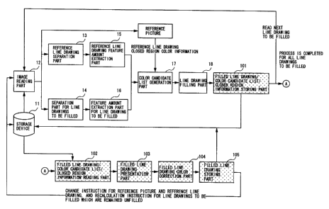
With reference to Fig. l9, the image
filling apparatus according to the first embodiment
of the present invention includes a storage device
11, an image reading part 12, a reference line
drawing separation part 13, a separation part for
line drawings to be filled 14, a reference line
drawing feature amount extraction part 15, a feature
amount extraction part for line drawing to be filled
16, a color candidate list generation part 17, a
line drawing'filling part 18 and a filled line
drawing storing part 19.
The storage device 11 stores a reference
line drawing, a reference picture and line drawings
CA 02471159 2004-07-12
78230-4E
-22-
to be filled as shown in Fig.20.
The image reading part 12 reads the a
reference line drawing, the reference picture and
the line drawing to be filled from the storage
device 11. In the case when the next line drawing
to be filled is filled by using the, same reference
picture and the same reference line drawing,. only
the next line drawing to be filled is read from the
storage device 11.
The reference line drawing separation part
13 extracts all closed regions which form the
reference line drawing. Each closed region to be
filled should be completely enclosed by a boundary
line (the color iswot limited to black), since the
closed region is filled digitally.
There are various method for separating
the closed region in an image. In this embodiment,
a method will be described as an example in which'a
different number is assigned to each closed region
which constitutes the reference line drawings.
Fig.21 shows an example of the format of the closed
region data generated by this method. As shown in
this figure, a closed region number is assigned to
each pixel wherein the closed region number
corresponds to the closed region including the pixel.
A special number (possible maximum number in the
case shown in Fig.21) is assigned to a pixel on the
boundary line such that it is identified that the
pixel is on the boundary line. In addition, by
assigning the special number, the boundary line is
protected from being filled when filling is
performed. The sizes of the x axis direction and
the y axis direction are the same as the pixel
numbers (x$lze. YSiZe) of the x axis direction and the
y axis direction of the reference line drawing
respectively.
Figs.22A and 22B shows flowcharts of the
CA 02471159 2004-07-12
78230-4E
-23-
process performed. In step 2l,~all data in the
closed region 1s initialized to the possible maximum
value (MAXVALUE). The MAXVALUE~is determined to be
more than the number of closed.regions which
constitute the reference. line drawing. In this
embodiment, the process starts from the closed
region number 0 and (x, y)=(0, 0) in steps 22, 23.
(0, 0) is determined as the seed point in this case.
When the closed region data of the corresponding
pixel is MAXVALUE and the color of the pixel is
white (thus, a colored line other than black is
treated as a boundary line), the closed region data
of the pixel is converted to 0 in steps 24-27.
After all data of the object closed region is
I5 converted to 0, the closed region data is
incremented by 1 in step 28. Then, the same
processing is repeated after finding a next seed
point in which the color is white and the value is
MAXVALUE. As a result, boundary lines which divides
the reference line drawing into closed regions have
MAXVALUE and each of the closed regions is numbered
by a different integer from 0 such that the closed
regions are separated.
In the closed region numbering process
shown in Fig.22B, (x, y) is substituted into (a, b)
in step 31. If a and b are bigger than 0 and if a
and b are smaller than xsiz, and ysiZB respectively
and if the color of (a, b) is white and the closed
region data is MAXVALUE, a specified number (closed
region number) is assigned to (a, b) as closed
region data in steps 32-34. Then, after each of a
and b is incremented and decremented by 1 in steps
35-38, the closed region numbering process (step 27)
is recursively called.
The separation part for line drawings to
be filled 14 performs the same processing to a line
drawing to be filled as the reference line drawing
CA 02471159 2004-07-12
78230-4E
-24-
separation part 13 performs. As a result, as in the
case of the reference line drawing, MAXVALUE is
assigned to the boundary line and the closed regions
are numbered by integers from 0.
The reference line drawing feature amount
extraction part 15 extracts a feature amount for
each closed region which is separated by the
reference line drawing separation part 13. In this
embodiment, the following seven kinds of feature
amounts are used as shown in Figs.23A-23F.
1. Central coordinates of a rectangular
circumscribing the closed region (Fig.23A)
2. The area of a rectangular circumscribing the
closed region (Fig.23B)
I5 3. The aspect ratio of a rectangular circumscribing
the closed region (Fig.23C)
4. The number of pixels constituting the closed
region (Fig.23D)
5. The ratio between 2. and 4. (Fig.23E)
6. The peripheral length of the closed region
(Fig.23F)
7. The ratio between the square roots of 6. and 4.
(Fig.23G)
In Figs.23A-23G, the boundary line is
shown for each closed region for the sake of clarity.
In reality, the boundary line is not included in the
separated closed region.
In the following, the calculation method
of the feature amounts 1-7 will be described.
In the following, Xmin(i). xmax(i). Ymin(i).
Y~ax(i) are assumed to be the minimum value, the
maximum value of x of the rectangular circumscribing
the closed region i, and the minimum value, the
maximum value of y of the rectangular circumscribing
the closed region i respectively, center(i).x and
center(i).y are assumed to be the x coordinate and
the y coordinate of the center of the rectangular
CA 02471159 2004-07-12
78230-4E
-25-
circumscribing the closed region 1, area_rec(i) is
assumed to be the area of the rectangular
circumscribing the closed region i, aspect_ratio(i)
is assumed to be the aspect ratio of the rectangular
circumscribing the closed region i, pixels(i) is
assumed to be the number of pixels constituting the
closed region 1, circum(i) is assumed to be the
peripheral pixel number of the closed region 1.
1. the calculation method for the feature
amount 1 (Figs.24A, 24B)
First , the parameters x~in ( 1 ) , xmax ( 1 ) ,
Ymin(i) . Y~ax(i) are initialized. In step 41, the
closed region number 1 is initialized. Then,
initialization of X~,in ( 1 ) =Xsize, Ymin ( 1 ) -Ysize . xmax ( 1 )
= 0 , y~~(i)= 0 is performed for every region in
steps 42-44. Next, as shown in Fig.24B, the
coordinates (center(i).x, center(i).y) of the center
of the rectangular circumscribing the closed region
1 are calculated. In steps 51-53, coordinates (x,
y) of the'closed region i ate scanned and the closed
region number of the coordinates is substituted into
1. When the closed region number 1 does not
represent the boundary line, x is substituted into
x,~in ( 1 ) if x < x,~in ( 1 ) , x 1s substituted Into xmax( 1 )
2 5 if x > x,~ax ( i ) , y is subs tituted Into y,uin ( 1 ) if y <
Yin ( 1 ) , y 1S substituted Into y,~ax( 1 ) 1f y > y,~aa 1 )
in steps 54 and 55. When the scan is completed, the
closed region number 1 is initialized in step 71.
Then, the coordinates (center(i).x, center(i).y) of
the center of the rectangular circumscribing the
closed region i in steps 72-74 are calculated.
2. The calculation method for the feature
amount 2 (Figs.25A, 25B)
First , the parameters x,~in ( 1 ) , x,~a~ ( 1 ) ,
ymin(i), Yroax(i) are initialized in the same way as
the feature amount 1 as shown in Fig.25A. Next, as
shown in Fig.25B, the area area rec(i) of the
CA 02471159 2004-07-12
78230-4E
-26-
rectangular circumscribing the closed region 1 is
calculated. This processing is the same as the case
of the feature amount 1 except that the step~75 is
performed instead of the step 73.
3. The calculation method for the feature
amount 3 (Figs.26A, Z6B)
First , the parameters xmin ( 1 ) , xmax ( 1 ) . Ymin
(1), Ymax(i) are initialized in the same way as the
cases of the feature amounts l, 2 as shown in
Fig.26A. Next, as shown in Fig.26B, the aspect
ratio aspect_ratio (1) of the rectangular
circumscribing the closed region 1 is calculated.
This processing is the same as the case of the
feature amount 1 except that the step 76 is
performed instead of the step 73.
4. The calculation method for the feature
amount 4 (Figs.27A, 27B)
First, the number of pixels pixels(i) in
the.closed region 1 which is necessary for
calculating the feature amount 4 is initialized as
shown in Fig.27A. For this purpose, the step 45 is
performed instead of the step 43 shown in Fig.24A.
Next, as shown in Fig.27B, the number of pixels
constituting the closed region i is calculated. For
this purpose, the step 56 is performed instead of
the step 55 shown in Fig.24B and the steps 71-74 are
not performed.
5. The calculation method for the feature
amount 5 (Figs.28A, 28B)
3 0 Firs t , Xmin ( 1 ) . xmax ( i ) . Ymin ( 1 ) . Ymax ( 1 ) .
pixels(i) which are necessary for calculating the
feature amount 5 are initialized as shown in Fig.28A.
For this purpose, the step 46 is performed instead
of the step 43 shown in Fig.24A. Next, as shown in
Fig.28B, the ratio between the area and the number
of pixels of the rectangular circumscribing the
closed region i ratio_rect pix(i) is calculated.
CA 02471159 2004-07-12
78230-4E
-27-
For this purpose, the step 57 is performed instead
of the step 55 shown in Fig.24B and the step 77 is
performed instead of the step 73.
6. The calculation method for the feature
amount 6 (Figs.29A, 29B)
First, the number of pixels constituting
the periphery of the closed region i which is
necessary for calculating the feature amount 6 are
initialized as shown in Fig.29A. For this purpose,
ZO the step 47 is performed instead of the step 43
shown in Fig.24A. Next, as shown in Fig.29B, the
peripheral length circum(i) of the closed region is
calculated. Before the scan of the y axis direction
is started, i,~ax which is the possible maximum number
for i is substituted into iota which is a closed
region number detected just previously in step 58.
In step 59, when i does not represent the boundary
line, it is judged whether iola < i,~~ and 1 $iola in
step 59. When the result is "NO", the process
returns to the step 52 since it means that the
corresponding pixel is in the outside of the
reference line drawing. When the result is "YES",
each of circum(i) and circum(iola) is incremented by
1 in step 60. Then, 1 is substituted into iala in
step 61.
~7. The' calculation method for the feature
amount 7 (Figs.30A, 30B)
First, pixels(i) and circum(i) Which are
necessary for calculating the feature amount 7 are
initialized as shown in Fig.30A. For this purpose,
the step 48 is performed instead of the step 43
shown in Fig.24A. Next, as shown in Fig.30B, the
ratio between the square root of pixels(i) and
circum(i) is calculated. For this purpose, the step
62 is added next to the step 54 shown in Fig.29B.
Figs.3lA and 31B show the method in which
the feature amounts 1-7 are calculated
CA 02471159 2004-07-12
78230-4E
-28-
simultaneously such that each feature amount can be
calculated with less calculation amount. The steps
49, 63, 78 are performed instead of the steps 48, 62,
77 shown in Figs.30A, 30B.
As mentioned above, the feature amounts
(feature amounts 1-5 in the following) of all closed
regions which constitutes the reference line, drawing
are calculated and stored for each closed region as
shown in Fig.32.
The feature amount extraction part for
line drawings to be filled 16 performs the same
processing as the processing by the reference line
drawing feature amount extraction part 15 to the
line drawing t-o be filled. As a result, the above-
mentioned feature amounts are stored for every
closed amount which constitutes the line drawing to
be filled.
The color~candidate list generation part
17 calculates variation amounts 'of the feature
amounts for all combinations between every closed '
region of the line drawing to be filled and every
closed region of the reference line drawing. The
definition of the variation amount differs according
to the kind of the feature amount. For example, it
is appropriate to consider the variation amount of
the feature amount 1 to be the distance between
coordinates and to consider the variation amount of
the feature amounts 2-5 to be the ratio. For a
feature amount, differences may be appropriately
used for the variation amount. For every variation
amount between the closed region of the line drawing
to be filled and the closed region of the reference
line drawing, when the variation amount is smaller
than one, the inverse of it is calculated, sorted in
ascending order and stored as shown in Fig.33.
Figs.33-36 shows the case in which the
reference line drawing includes four closed region.
CA 02471159 2004-07-12
78230-4E
-29-
In the description for the Figs~.33-36, the number of
the closed region of the. line drawings to be filled
is not mentioned. There occurs~no problem if the
number of the closed region between the reference
line drawing and the line drawing to be filled is
different.
Next, each variation amount of the closed
region of the line drawing to be filled is
normalized. In this embodiment, when it can be
regarded that the smaller the variation amount is,
the closer the feature is between the corresponding
closed regions of the line drawing to be filled and
the reference line drawing, the minimum value V,~in of
the variation amount is normalized to 0.0 and the
maximum value Vmax of the variation amount is
normalized to 1Ø As for the above-mentioned five
feature amounts, this assumption is applicable.
The value Vor9 between Vein and Vm~ can be
converted to the following value V by applying
simple linear transformation.
V- Vorg-Vmin
V max- V min
This normalization is performed to every variation
amount. Fig.34 shows an example of the result.
Next, the variation amounts which are
calculated for each feature amount are integrated
and evaluated. The user can specify weights for
each of the variation amounts ~Vl , Vz , V3 , V4 , V5) of
feature amounts. In this embodiment, the weights
are represented as W1, Wz , W3 , W,, , W5 and these are
provided after normalized as O.OSWl, Wz. Ws. W4. W3S
1Ø 8y using these weights, integrated variation
amounts between every closed region of the line
drawing to~be filled and every closed region of the
reference line drawing are calculated from.the
following equation.
CA 02471159 2005-08-22
78230-4E
-30-
Veq= W1~Vi-~WZ'V2~-W3'V3-~-W4'V4~-I-WS'VS ~2)
This calculation is performed for each of
the variation amounts. Then, the results of the
calculation are sorted in ascending.order as shown
in Fig.35.
Next, the color corresponding to the
closed region of the reference line drawing is
extracted from the reference picture. When two or
more closed regions of the reference line drawing
has the same color on the reference picture,
duplication is eliminated from below in the list as
shown in Fig.36. In this way, the color candidate
-list is generated in the order of certainty~for
every closed region of the line drawing to be filled
as shown in Fig.36.
The user can specify a threshold for the
variation amount of each feature amount. In this,
case, the combination of the closed regions. in which
at least a variation amount exceeds the threshold
should be below a combination which does not exceed
any threshold for every variation amount in the list
after being integrated by the formula (2) and sorted.
The manipulations for this are performed when
performing normalization. For this, the
normalization using the formula (1) is performed for
values~which do not exceed the threshold, wherein
V~ax is regarded as the maximum value which does not
exceed the threshold.- A value which satisfies the
following equation is provided for values which
exceed the threshold. For example, the variation
amount for the feature amount 1 exceeds the
threshold, the value which satisfies the following
inequation is provided.
V~.rl~ W1+W2-I-WgHW4~-WS
CA 02471159 2005-08-22
78230-4E
-31-
As a result, even when all of the other
variation amounts which are normalized are 0, the
integrated variation amount becomes more than an
integrated amount in the case when all of normalized
variation amount are 1. Thus, the color candidate
list may be generated including the value. In
addition, the value may be excluded. In~the above
inequation (3) , when Wl=0 , the result of the equation
becomes indeterminate. In such a case, any value
which is substituted into Veil is not evaluated in
the equation (2).
In addition, if the variation amounts of
the feature amounts 2 and 4 decreases as the closed
region becomes large, for example, when a camera
approaches an object or the object approaches the
camera', the variation amounts are regarded as
exceeding the thresholds. Conversely, if the
variation amounts of the feature amounts 2 and 4
increases as the closed region becomes small, for
example, when a camera moves away from an object or
the object moves away from the camera, the variation
amounts are regarded as exceeding the thresholds.
As a result of this, the color candidate list
becomes more certain.
The line drawing filling part 18 colors
every closed region of the line drawing to be filled
with the top color in the color candidate list for
the closed region. There are various methods for
filling. In this embodiment, a method which
conforms to the above-mentioned separation method of
the closed region will be described with reference
to Figs.37A and 37B.
In steps 81-83, filling is started by
pointing coordinates (x, y) in the closed region to
35_ be filled as a seed point. If the coordinates (x,
y) are appropriate~and if the closed region data of
the coordinates (x, y) is the same as a specified
CA 02471159 2004-07-12
78230-4E
-32-
closed region data, the specified color value is
provided to the coordinates in steps 91-94.
Then, each of x and y is incremented or
decremented by 1 for performing the above-mentioned
process on coordinates.around the seed point in
steps 95-98. Then, the gaint processing is
recursively called. According to the above-,
mentioned process, filling an unrelated closed
region with an unrelated color can be prevented such
that the boundary line is completely protected.
The filled line drawing storing part 19
' stores the filled line drawing which is filled
according to the above-mentioned process in the
storage device 11. This process will not be
described in detail since this process is general.
After completing the above-mentioned
process, next line drawing to be filled is read and
filled in the same way. When the same reference'
picture / reference line drawing are used, the image
reading part l2 is instructed to read the next line
drawing leaving all information on the reference
picture / reference line drawing retained. In the
case, processing by the reference line drawing
separation part 13 and reference line drawing
feature amount extraction part 15 is not necessary.
In addition, when using the filled line drawing and
the original line drawing as a new reference picture
/ a new reference line drawing, all information of
the filled line drawing is moved to the reference
picture and all information of the original line
drawing is moved to the reference line drawing.
After that, the image reading part 12 is instructed
to read the next line drawing to be filled. Then,
the next line drawing is filled by the above-
mentioned processing. If the reference picture /
the reference line drawing are newly specified, the
above-mentioned process is performed.
CA 02471159 2004-07-12
78230-4E
-33-
Fig.38 is a block diagram showing the
image filling apparatus according to a second
embodiment of the present invention. This image
filling apparatus of the second embodiment includes
a filled line drawing/color candidate list/closed
region information storing part 101 instead of the
filled line drawing storing part 19 of the first
embodiment shown in Fig. l9. In addition, a filled
line drawing/color candidate list%closed region
information reading part 102, a filled line drawing
presentation part 103, a filled line drawing color
correction part 104 and a filled line drawing
storing part 105.
The filled line drawing/color candidate
list/closed region information storing part 101
stores only the filled line drawing in the first
embodiment. In the second embodiment, the filled
line drawing/color candidate list/closed region
information storing part 101 stores the
corresponding color candidate list and the separated
closed line data additionally. Every specified line
drawing to be filled is stored in the storage device
11.
The filled line drawing/color candidate
list/closed region information reading part 102
reads successively the color candidate list and the
closed region information corresponding to the
filled line drawing from the storage device 11
according to instructions by the user, wherein the
color candidate list and the closed region
information corresponding to the filled line drawing
are obtained by filling processing for all specified
line drawings.
The filled line drawing presentation part
103 displays the filled line drawing to a monitor
such as a CRT, a LCD and the like.
The filled line drawing color correction
CA 02471159 2004-07-12
78230-4E
-34-
part 104 changes a color of a closed region. More
specifically, when the user clicks a mouse button on
a closed region specified by the mouse pointer in
the filled line drawing displayed on the monitor,
the closed region number is identified from the
coordinates of the mouse pointer. Then, the color
candidate list corresponding to the closed region
number is displayed on the filled line drawing in
which the color order of the displayed list is the
same. When the user selects a color in the list
with the mouse pointer, the color of the specified
closed region is changed to the selected color.
Thus, even when there is an error in colors
determined in the first embodiment, the color can be
easily changed with a small mouse movement since it
is probable that the correct color is in the upper
part of the list.
Fig.39 shows an example of the displayed
color candidate list. The order of candidate colors
is the same as that in the color candidate list
obtained in the first embodiment. At the beginning,
the region is filled with the top color in the list.
If only the colors of the color candidate list are
displayed, it becomes difficult to select a color
when similar colors are used. Therefore, in this
embodiment, the color data is displayed next to the
color. In addition, if (R, G, B)=(255, 255, 255) is
treated as transparent, it is difficult to
recognizes the difference between transparent (255,
255, 255) and white (254, 254, 254) on the screen.
In this case, the user can easily recognize the
difference since the color data is displayed.
Moreover, a description which describes that the
color is transparent is displayed on the color (in
this case °transparent") such that the user can
recognize the color.
When the selected color is different from
CA 02471159 2004-07-12
78230-4E
-35-
a color which is already filledy the closed region
is filled with the specified color. Fo'r this
purpose, the processing shown in Figs.37A and 37B
can be used. ,
The filled line drawing storing part 105
stores the filled line drawing in which the color is
changed in the storage device 11. The corresponding
color candidate list is not necessarily stored since
it is the same as the stored color candidate list.
When every filled line drawing which is
automatically filled in the first embodiment needs
to be checked and corrected by the user, the user
repeats the above-mentioned operation. The filled
line drawing.which~is checked and corrected.by the
user may be used as the reference picture, and the
original line drawing may be used as the reference
line drawing such that line drawings which are
remained unfilled are automatically filled again.
In this case, the image reading part l2 is
instructed to change the reference picture and the
reference line drawing, and to calculate the line
drawings to be filled. By using the corrected
filled line drawing, the line drawings to be filled
next can be filled automatically more properly.
Fig.40 shows a block diagram of an image
filling apparatus according to a third embodiment of
the present invention. The image filling apparatus
of the third embodiment includes a filled line
drawing/color candidate list/closed region
information storing part 101' and a filled line
drawing color correction part 104' instead of the
filled line drawing/color candidate list/closed
region information storing part 101 and the filled
line drawing color correction part 104 of the second
embodiment. In addition, a color alias list
generation storing part 106 and a color alias list
reading part 107 are provided.
CA 02471159 2004-07-12
78230-4E
-36-
The color .alias list,generation storing
part 106 provides and stores aliases of the colors
used in a sequence in color correction of the second
embodiment. For example, aliases which are easy to
identify and are self-explanatory for performing
color correction in the second embodiment are
entered as shown Fig.4l. The color alias list is
stored in the form shown in Fig.42.
The color alias list reading part 107
reads one or a plurality of color alias lists stored
in the storage device II. '
The filled line drawing color correction
part 104' displays the color alias list with the
corresponding color of the color candidate list as
shown in Fig.43. Thus, an filling error can be
checked and corrected more easily than the second
embodiment.
As shown in Fig.44, the image filling
apparatus of the embodiments of the present
invention can also be configured by an input
apparatus 110, storage devices 111, 112, an output
device 113,, a recording medium 114 and a data
processing apparatus 115. The input device 110
inputs data such as images. The storage medium 111
corresponds to the storage device 11 in Figs.l9, 38,
40. The storage device 112 corresponds to a main
storage. The output device 113 displays data such
as images. The recording medium 114 is, for example,
a FD (floppy disk), a CD-ROM, an MO (magneto-optic
disk) and the like, and stores a image filling
program which has parts shown in Figs.l9, 38, 40.
The data processing apparatus 115 is a CPU which
reads the image filling program from the storage
device 114 and executes it.
According to the present invention, the
computational amount can be decreased when
determining the color used for. filling the closed
CA 02471159 2004-07-12
78230-4E
-37-
region of the line drawing with,reference to the
reference line drawing. In addition, the color
candidate list is generated in which the candidate
colors are sorted in the order of certainty for
every closed region of the line drawing to be filled.
Further, the top color in the list is used for
automatically filling. Thus, any unffilled region
does not remain.
Furthermore, it is easy to check and
correct the error of the color. Thus, the user can
save effort for filling.
(fourth embodiment)
Next, the fourth embodiment of the present
invention will be described with reference to
figures. The fourth embodiment corresponds to the
second object.
As shown in Fig.45, the image filling
apparatus of the fourth embodiment includes a
storage device 211, a line drawing to be filled
reading part 212, a boundary line information
extraction Bart 213, a filling part 214, a colored
line filling part 215, a filled line drawing storing
part 216 and an image display device 217, a pointing
device, keyboard and the like.
The storage device 211 stores line
drawings to be filled which include colored lines.
The line drawing to be filled reading part 212 reads
the line drawing to be filled from the storage
device 211. The boundary line information
extraction part 213 extracts a boundary line by
using the color of the line drawing to be filled as
a key.
Fig.46 shows an example of the boundary
line information which is generated. In this
embodiment, there are four kinds of boundary lines
which are black, red, green, blue (as the colored
line, there are three kinds, red, green, blue). One
CA 02471159 2004-07-12
78230-4E
-3$-
bit is assigned to each pixel of the boundary line
information for a color. In the figure, x,iZ, and y
Size represent the number of pixels horizontally and
vertically respectively. 0 is assigned to a pixel
of the region (white) other than the boundary line
as the boundary line information. Therefore, there
are five kinds of color information, which are white,
black, red, green, blue. Thus, three bits are
enough for representing one pixel of the boundary
line information since the colors are mutually
independent events. However, assigning three bits
is equivalent to assigning four bits to the boundary
line information for one pixel since memory amount
for storing the boundary line information in the
case of assigning three bits is the same as that in
the case of assigning four bits due to the byte
length. In addition, when the user treats the three
kinds (red, green, blue) of colored~line likewise',
two bits are enough. In this case, it becomes
impossible to recover the color of the colored line
when an error is detected after changing the color
of the colored line by after-mentioned colored line
filling part 15. However, when there is no problem-
if the changed color is recovered to a color, for
example, red, two bits can be assigned to the
boundary line information for one pixel such that
the memory amount can be decreased.
Fig.47 shows an example of extraction of
the boundary line information. A threshold is
provided for each of R, G, H by the use beforehand
as Rtnr, Gxnr ~ Htar ~ In step 221, the boundary line
information is initialized. Then, the line drawing
to be filled is scanned in the x axis direction and
y axis direction in steps 222, 223. Color
information.(r, g, b) of (x, y) is extracted in step
224. Then, the pixels of the line drawing are
scanned while comparing color information (r, g, b)
CA 02471159 2005-08-22
78230-4E
-39-
of each pixel with the thresholds Rtnr. Gtnr. Btnr in steps
225, 227, 229, 231, 233.
If every color r, g, b is larger than or equal to
the corresponding threshold, that is, if the following
inequations are satisfied,
r ~ Rthr
g ~ Gthr
b ~ Bthr
the pixel is determined to be white and 0000 is set to the
boundary line information which corresponds to the pixel
(x, y) in step 226.
If every color r, g, b is smaller than the
corresponding threshold, that is, if the following
inequations are satisfied,
r < Rthr
g < Gthr (5)
b < Bthr
the pixel is determined to be black and 1000 is set to the
boundary line information which corresponds to the pixel
(x, y) in step 228.
If only r is larger than or equal to the
corresponding threshold Rtnr and g, b are smaller than Gtnr.
Btnr respectively, that is, if the following inequations are
satisfied,
2 5 r >- Rthr
g < Gtnr
b < Bthr
CA 02471159 2005-08-22
78230-4E
-40-
the pixel is determined to be red and 0100 is set to the
boundary line information which corresponds to the pixel
(x, y) in step 230.
If only g is larger than or equal to the
corresponding threshold Gtr,r and r, b are smaller than Rthr.
Bthr respectively, that is, if the following inequations are
satisfied,
r < Rthr
g ~ Gthr (7)
b < Bthr
the pixel is determined to be green and 0010 is set to the
boundary line information which corresponds to the pixel
(x, y) in step 232.
If only b is larger than or equal to the
corresponding threshold Btnr and r, g are smaller than Rthrr
Gtnr respectively, that is, if the following inequations are
satisfied,
r < Rthr
g < Gthr (8)
b >- Bthr
the pixel is determined to be blue and 0001 is set to the
boundary line information which corresponds to the pixel
(x, y) in step 234.
The above-mentioned process by using the
inequations (4) - (8) is displayed to the image display
device 217 one after another such that the user can change
the thresholds Rtnr. Gtnr~ Brhr while checking the process on
the display device.
CA 02471159 2005-08-22
78230-4E
-40a-
When a pixel which does not satisfy any one of
inequations (4) - (8) is detected, the image filling
apparatus makes an inquiry to the user whether the
thresholds need to be changed or the pixel is not on the
boundary line in step 235. In the former, the apparatus
requests to the user to input new thresholds after
suspending the process. In the latter, the process is
continued after 0000 is set to the boundary line information
which corresponds to the pixel in step 236.
20 In this embodiment as shown in Fig. 47, the
boundary line is judged in the order of white, black, red,
green, blue. However, any other order can be used since the
colors are mutually independent for a
CA 02471159 2004-07-12
78230-4E
-41-
pixel.
The filling part 214 colors the region
other than the boundary line by~using the boundary
line information which is generated by the boundary
line information extraction part 213. More
specifically, only the region which has 0000 as the
boundary information is filled in this embodiment.
General filling method can be used for filling
regions which have other than 0000 as the boundary
information. Fig.48 shows an example. In this
example, the line drawing to be filled is displayed
on the image display device 217 one after another
while the user colors the line drawing to be filled.
Coloring is started from coordinates (x, y) which is
pointed by the user with a pointing device such as a
mouse, in which the color used for filling is
specified by the user with the pointing device, a
keyboard or the like in step 241. When the
coordinates is in the line drawing to be filled, the
boundary information is 0000 and the color of (x, y)
is not the same as the color which the user
specifies, specified color information is assigned
to the coordinates in steps 242-245. The same
process (paint process) is performed to coordinates
around the coordinates recursively in steps 246-249.
Thus, the closed region which includes the
coordinates specified initially by the user and does
not include the boundary Line is filled by the color
specified by the user.
As a result, the line drawing is filled
without filling the boundary line. The filled line
drawing to be filled is called the filled line
drawing.
The colored line filling part 215 changes
the color.of the colored line (boundary line) to an
appropriate color.
The processing by the colored line filling
CA 02471159 2004-07-12
78230-4E
~ -42-
part 215 will be described with reference to
Figs.49A and 49B. In the following description, a
mouse is used for a pointing device. If the mouse
is replaced by a trackball, a graphics tablet or the
like, the following method is the same.
As shown in Fig.49A, when, a mouse button
and a button of the keyboard (for example, a control
button in this case) are pushed, color information
(r, g, b) of the coordinates at the mouse pointer on
the line drawing is obtained if the boundary line
information of the coordinates is 0000 in steps 251-
254. If the boundary line information is not 0000,
nothing is done. When only the mouse button is
pushed, the obtained color information (r, g, b) is
set to the coordinates at the mouse pointer if the
boundary line information at the coordinates is 0100
or 0010 or 0001 until a mouse up event is detected
(that is, while the mouse button is pushed) in s ups
255-257. Accordingly, in the case shown in Fig.49A,
the color specified by the mouse pointer is obtained
when the mouse button is pushed in conjunction with
the control button. Then, when the mouse pointer is
moved while pushing only the mouse button, the color
of a part of the boundary line on which the mouse
pointer passed is changed to the obtained color.
Therefore, when the user wants to change
the color of the boundary line (colored line) to a
brighter color of region colors divided by the
boundary line, the user may push the mouse button in
conjunction with the control button at the side of
the brighter color for obtaining the color, and,
then, the user may move the mouse pointer on a part
where the user wants to change the color while
pushing the mouse button. Then, the color of the
part is changed to the color the user wants. When
there region plurality of different color regions
divided by colored lines, only.a color of a part of
CA 02471159 2004-07-12
78230-4E
-43-
the colored line can~be changed in the same way.
When the mouse has two mouse buttons, the above-
mentioned process can be realized by pushing the
. left button instead of pushing~only the above-
5. mentioned mouse button and by pushing the right
button instead of pushing the mouse button with the
control button.
In the case shown in Fig.49B, when the
mouse button is pushed and the boundary line
information of the coordinates at the mouse pointer
is 0000, the color information (r, g, b) is obtained
in steps 261-263. In other cases (0100 or 0010 or
0001), the color of the coordinates specified the
mouse pointer is changed to the obtained color until
a mouse up event is detected (that is, while the
mouse button is pushed). Thus, according to the
method shown in Fig.49B, when the mouse pointer is
moved from a region to another region across the
colored line, the color of the colored line is
changed to the color of the region where the mouse
pointer is initially located. Therefore, when the
user pushes the mouse button at a brighter color
region of regions divided by the colored line and
moves the mouse pointer on a part of the colored
line where the user wants to change the color, the
color of the part where the mouse pointer passed
through can be changed to the brighter color as
shown in F1g.50. When there are plurality of
different color regions divided by colored lines,
the color of only a part of the colored line can be
changed in the same way.
In both of the methods shown in Figs.49A
and 49B, since all boundary line information is kept
stored, the above-mentioned process can be performed
any number of times when the user makes a mistake.
In addition, since each of the colored lines of red,
blue, green is represented separately in the
CA 02471159 2004-07-12
78230-4E
-44-
boundary line information, the changed color of the
colored line can be turned back to the initial state.
The present invention and the paint bucket
tool can be combined. More specifically, when a
colored line should be filled with a plurality of.
colors, the user divides the colored line by using
the present invention as shown in Fig.5lA. Then,
the user can color the divided colored line with the
paint bucket tool as shown in Fig.5lB.
The filled line drawing storing part 216
stores the filled line drawing in the storage device
11.
As shown in Fig.52, the image filling
apparatus of the embodiments of the present
invention can also be configured by a mouse 71,
storage devices 72, 73, an output device 74, a
recording medium 75 and a data processing apparatus
76. The storage device 72 corresponds to the
storage device 211 in Fig.45. The storage device 73
is a main storage device. The output device 74
displays data such as images. The recording medium
75 corresponds to a recording medium such as a FD
(floppy disk), a CD-ROM, an MO (magneto-optic disk)
and the like which stores an image filling program
which has the line drawing to be filled reading part
212 - the filled line drawing storing part 216 shown
in Fig.45. The data processing apparatus 76 is a
CPU which reads the image filling program from the
recording medium 75 and executes it.
According to the present invention, the
color of the colored line can be changed without
being affected from filling operation of other
regions. Thus, it is not necessary for the user to
consider the filling order. In addition, even when
a colored line extends over a plurality of regions,
the user can change the color of only a necessary
part of the colored line without affecting other
CA 02471159 2004-07-12
78230-4E
~ -45-
regions. Thus, the user can perform filling
effectively and flexibly.
The above-mentioned fourth embodiment can
be realized in concert with other embodiments of the
present invention. For example, the fourth
embodiment can be used for filling the colored line
in the first - third embodiments.
(fifth embodiment)
In the following, the fifth embodiment
will be described with reference to figures. The
fifth embodiment corresponds to the third object of
the present invention.
As shown in Fig.53, an image filling
apparatus of the fifth embodiment includes a color
specifying information generation part 311, a color
specifying information storing part 312, a storage
device 313, a line drawing to be filled reading part
3I4, a line drawing displaying part 3'15, a color
specifying information reading part 316, a filling
part 317yand a filled line drawing storing part 318.
The color specifying information
generation part 311 generates color specifying
information according to instructions by the user,
wherein the color specifying information includes
colors used for filling and names corresponding to
the colors. Fig.54 shows an example of the color
specifying information.
The color specifying information storing
part 312 stores the generated color specifying
information in the storage device 313.
The storage device 313 stores line
drawings to be filled, the color specifying
information and filled line drawings.
The line drawing to be filled reading part
314 reads the line drawing to be filled from the
storage device 313 according to instructions by the
user.
CA 02471159 2004-07-12
78230-4E
-46-
The line drawing displaying part 315
displays the line drawing to be filled on a image
displaying device 319 such as a CRT.
The color specifying information reading
part 316 reads the color specifying information from
the storage device according to instructions by the
user.
The filling part 317 obtains coordinates
in a closed region where the user wants to color in
the line drawing to be filled displayed on the image.
displaying device 319, in which the coordinates are
specified by a pointing device. Then, the filling
part 317 overlays the color specifying information
on the line drawing at the coordinates. When the
I5 user specifies a color in the color specifying
information with a-pointing device, the filling part
3I7 obtains the corresponding color value from the
color specifying information and colors the closed
region specified by~the coordinates with the
specified color.
In the following, the fifth embodiment
will be described more specifically with reference
to Figs.55, 56, 57A, 57B, 57C.
In the process shown in Fig.55, a mouse
which has one button is used as the pointing device.
In step 301, the user pushes the mouse button at
coordinates in a closed region in the line drawing
to be filled where the user wants to color by using
the mouse cursor displayed on the image displaying
device 319. Then, coordinates at the mouse cursor
are obtained when the mouse button is pushed, and
the coordinates are sat in (x, y) in step 302. It
is checked whether (x, y) is in the line drawing to
be filled in step 303. If (x, y) is not in the line
drawing, the process is completed without performing
any process. If (x, y) is in the line drawing, the
color specifying information which was previously
CA 02471159 2004-07-12
78230-4E
-47-
read is displayed at.(x, y) overlaying on the line
drawing to be filled as shown in Fig.57A in step 304.
The user moves the mouse cursor~to a color in the
color specifying information which the user wants
for filling while pushing the mouse button as shown
in Fig.57B. Then, the user releases the mouse
button in step 305. The coordinates at the time of
releasing the mouse button are obtained in step 306.
In step 307, it is checked whether the coordinates
is on an effective region in the color specifying
information. If not, the color specifying
information is deleted from the screen and the
process is completed in step 310. If the
coordinates are on the effective region in the color
specifying information, the color value
corresponding to the coordinates are obtained from
the color specifying information in step 308, and an
paint processing is performed bypassing (x, y) and
(R, G, B) to the paint process in step 309. Then,
the closed region including (x, y) is filled with (R,
G, B) in step 311. When the paint processing is
completed, the color specifying information is
deleted from the screen as shown in Fig.57C in step
310. The above-mentioned process is repeated until
filling of the line drawing is completed.
Fig.56 shows an example of the paint
processing. As mentioned above, when filling the
closed region, it is necessary to specify the
coordinates in the closed region and the color value.
There are various methods for filling the closed
region by using the coordinates and the color value.
In this embodiment, a method using a recursive call
will be described.
The (x, y) passed from the step 310 is
saved in working coordinates (a, b) in step 321. It
is checked whether (a, b) are on the line drawing to
be filled and do not have the color of the boundary
CA 02471159 2004-07-12
78230-4E
-48-
line in step 322. If this condition is not
satisfied, the process returns in step 328. When it
is satisfied, the color of (a, b) in the line
drawing is changed to the color (R, G, B) which was
passed from the step 310.1n 323. After that,
coordinates which are adjacent to (a, b) are
generated and are input to (x, y) in steps 324-327.
Then, this paint process is recursively called in
step 329. Accordingly, filling by (R, G, B) is
performed from (x, y) passed from the step 310 until
the coordinates reach the boundary line or the end
of the closed region. That is, the inside of the
closed region is filled~with the color (R, G, B).
The filled line drawing storing part 318
stores the filled line drawing in the storage device
313.-
As shown in Fig.58, the image filling
apparatus of the embodiments of the present
invention can also be configured by an input device
321, storage devices 322, 323, a display device 324,
a recording medium 325 and a data processing
apparatus 326. The input device 321 is a pointing
device, keyboard and the like for inputting colors
and the corresponding names. The storage device 322
corresponds to the storage device 313 in Fig.53.
The storage device 322 is a hard disk for example.
The display device 324 corresponds to the image
displaying device 319 in Fig.53. The recording
medium 325 corresponds to a recording medium such as
a FD (floppy disk), a CD-ROM, an MO (magneto-optic
disk) and the like which stores an image filling
program which has the color specifying information
generation part 311, the color specifying
information storing part 312, the line drawing to be
filled reading part 314, the line drawing displaying
part 315, the color specifying information reading
part 316, the filling part 317 and the filled line
CA 02471159 2004-07-12
78230-4E
-49-
drawing storing part.318. The data processing
apparatus 326 is a CPU which reads the image ffilling
program from the recording medium 325 and executes
it.
According to the above-mentioned invention,
the user can save labor in producing animation in
which digitized. line drawings are filled with
predetermined colors. That is because the user can
specify a color for filling the line drawing with
small movement of the pointing device.
The above-mentioned fifth embodiment can
be realized in concert with other embodiments of the
present invention. For example, the fifth
embodiment can be used with the first - third
embodiments. In addition, the color which is
painted by the first - third embodiments can be
changed by the fifth embodiment. Thus, filling
becomes speedy and accurate.
(sixth embodiment)
The sixth embodiment of the present
invention will be described in the following. The
sixth embodiment corresponds to the fourth object of
the present invention.
Fig.59 shows an example of an image
processing apparatus of the sixth embodiment. The
image processing apparatus includes a display 410, a
keyboard 420, a pointing device 430 (a mouse), a
printer 440, a processing device 450, a memory
device 460 and an external storage device 470. This
configuration itself is basically the same as a
computer system.
The processing device 450 includes an
image reading part 451, a small region searching
part 452, a small region changing part 453 and an
image writing part 454. The processing device 450
also includes a control part and the like which is
not shown in the figure for controlling each part.
CA 02471159 2004-07-12
78230-4E
-50-
The memory device 460 is a so-called working memory.
The memory device 460 stores small region size data
461 which is input from the keyboard 420, a search
state di$play table 463 and a small region table 463
which are generated by the small region searching
part 420, and image data 464 which is processed
halfway. The memory device 460 may be included in
the processing device 450.
The external storage device 470 stores an
unfilled line drawing file and a line drawing file
which is filled by the four connected pixel fill
seed algorithm or the scan line seed fill algorithm.
The line drawing will be called an image file in the
following. This storage device can be realized by a
magnetic disc, a magneto-optic disk or ang other
devices. The external storage device 470 may be
included in the memory device 460.
The image reading part 451 reads an object
image file which is stored in the external storage
20- device 470, stores it in the memory device (the
working memory) 460 as the image data 464 and
displays it on the display 410. The image data to
be processed may be also input by an image scanner
for example. The small region searching part 452
generates the search state display table 462 and the
small region table 463 on the memory device 460.
Then, the small region searching part 452 searches
the image data 464 for extracting small regions
which are smaller than the small region size (for
example, one pixel, two pixels) which is specified
beforehand by the user, wherein the searched pixel
is recorded in the search state display table 462
and the extracted small region is recorded in the
small region table 463.
The small region changing part 453 reads
the small region table 463 from the memory device
460. Then, the small region changing part 453
CA 02471159 2004-07-12
7$230-4E
-51-
displays a mark representing the small region
extracted by the small region searching'part 452 on
the image data, and makes an inquiry about next
processes for the extracted small region to the user.
The user provides instructions about the next
processes by the keyboard 420 or the mouse 430. The
small region changing part 453 performs processing
on the small region according to the instructions
such that the image data 464 in the memory device is
changed. The processing by the small region
changing part is performed in an interactive manner
between the user and the apparatus wherein the small
region changing process is displayed on the display
410 one.after another. The image writing part 455
writes the image data 454 which,is processed to the
external storage device 470. .The processed image
data may be printed out by the printer 440 according
to a user's instruction and the like.
In the following, the processes by the
small region searching part 452 and the small region
changing part 453 will be described in detail.
Fig.60 shows the search state display
table 462 for checking the searched pixel in the
image data 464. The search state display table 462
is generated corresponding to each of image data 464
to be processed. In the table, one bit is assigned
for one pixel because it is enough to represent two
states (unsearched or searched) for one pixel, for
example, 0 is assigned to the unsearched state and 1
1 assigned to the searched state. The sizes of the
x, y directions are the same as the sizes (Xsize,
Ysize) of the image data 464 to be processed.
Fig.61 shows the small region table 463
which stores the extracted small regions (a small
region list). The small region table 463 has the
number of extracted small region (count), the size
(number of pixels) of each small region (num),
CA 02471159 2004-07-12
78230-4E
' -52-
coordinates x, y of a pixel which is in the each
small region and a flag indicating whether the small
region has been processed by the small region
changing part 453 (change state flag). In the same
way as the search state display table 462, the small
region table 463 is generated for each image data
464 to be processed.
Figs.62-65 show process flowcharts of the
small region searching part 452. Fig.62 is a
flowchart showing the whole process of the small
region searching part 452, Figs.63 and 64 shows
generation and initialization flow of the search
state display table, and Fig.65 shows a search
process flow.
The process flow shown in Fig.63 is used
for checking small regions included in image data
whichever the small region is unfilled or filled.
The process flow shown in Fig.64 is used for
checking unfilled small regions included in image
data in which the image data has been filled by the
4 connected pixel fill algorithm or the scan line
seed fill algorithm and the like. The process shown
in Fig.63 is effective for prevent the user from
forgetting about changing a color of the small
region. The user specifies the flow shown in Fig.63
or 6 4 beforehand .
. In step 421, the small region searching
part 452 generates and initializes the search state
display table 462. As mentioned above, the process
flow shown in Fig.63 is used when checking small
regions included in image data 464 whichever the
small region is unfilled or filled. The process
flow shown in Fig.64 is used when checking unfilled
small regions included in image data 464.
When checking small regions included in
image data whichever the small region is unfilled or
filled, it is unnecessary to search lines included
CA 02471159 2004-07-12
78230-4E
-53-
in the image data. Therefore, 1~(searched state) is
assigned to coordinates of a pixel of a
predetermined color representing~the line, and 0
(unsearched) is assigned to coordinates of a pixel
which not is included in the line since searching is
necessary for the pixel.
As shown in Fig.63, states of all pixels
in the search state display table 462 are
initialized to 0 in step 441, and the image data 464
is scanned in steps 442 and 443. Then, when the
color of a scanned pixel is not the line color, the
state of the corresponding coordinates remains 0,
and when it is the line color, the state is changed
.to 1 in steps 444, 445.
When checking only unfilled small regions,
it is necessary to search unfilled pixels.
Therefore, 0 is set to the state of the coordinates
of the unfilled pixel since searching is necessary
for the unfilled pixel, ~ and 1 is set to the state- of
the coordinates of the filled pixel since searching
is not necessary for the filled pixel.
As shown in Fig.64, states of all pixels
in the search state display table 462 are
initialized to 0 (unsearched) in step 451, and the
image data is scanned in steps 452 and 453. Then,
when the scanned pixel is unfilled, the state of the
corresponding coordinates remains 0, and When it is
filled, the state is changed to 1 in steps 454, 455.
Next, the small region searching part 452
generates and initializes the small region table 463
in step 422. For this, all information is changed
to 0 except the number.
After that, the small region searching
part 452 initializes the number of the small regions
(count) to 0 in step 423, and scans the~search state
display table 462 in steps 424 and 425. When an
unsearched pixel is found, working variables
CA 02471159 2004-07-12
78230-4E
-54-
(counter of pixels ..pixels, the x coordinate of a
pixel in the small region . 1, the y coordinate of a
pixel in the small region . m) are initialized in
steps 426 and 427. Than, the searching,process
shown in Fig.65 is called in step 428.
In the searching process shown in Fig.65,
after the coordinates (a, b) at the time when the
process is called are set in step 461, it is checked
Whether the coordinates is in the image data and
unsearched. When the coordinates is not in the
image data or searched, the process returns. When
the coordinates is in the image data and unsearched,
the coordinates (the pixel) in the search state
table 462 are changed to searched in step 464, the
I5 working variable counter (pixels) is incremented by
lain step 465, and a, b are substituted into l, m
respectively in step 466. Then, four coordinates
around the pixel are generated in steps 467-470 so
that the same searching process is recursively
called.
After the searching process shown in
Fig.65 ends, the small region searching part 452
checks the size of the working variable (pixels) in
step 429. If the size is larger than the small
region size 461 specified by the user, the region is
not regarded as a small region. Thus, the process
returns to the step 425 in which the search state
display table is scanned. When the size is smaller
than or equal to the small region, size 461 specified
by the user, the value of "pixels" is substituted
into num(count], the value of "1" is substituted
into x[count], and the value of "m" is substituted
into y(count] in step 430. Then, "count" which
represents the small region number is incremented by
1 in step 431 and the same process is repeated.
According to the above-mentioned procedure,
the number of all extracted small regions, the size
CA 02471159 2004-07-12
78230-4E
' -55-
of each small region. and coordinates of a pixel
included in the small region are obtained regardless
of whether the image data is unffilled or filled.
They are stored in the small region table 463 as the
small region list. .
Fig.66 shows a process flow example of the
small region changing part 453. The small region
changing part 453 performs processes for each small
region extracted by the small region searching part ,
452 in an interactive manner with the user. In this
embodiment, the processes include
(1)filling a region with a color 'other than that of
the outline (filling of the small region)
(2)filling a region with a color of the outline '
(filling the small region with the color of the
outline)
(3)removing pixels of the outline (enlarging the
small region by deleting the pixels constituting the
outline~while keeping the closed region, and
filling)
(4)maintaining the existing state (maintaining the
small region as it is)
As shown in Fig.66, the small region
changing part 453 reads the small region table 463
from the memory device 460 in step 481 and
initializes the working variable (the small region
number counter . i) in step 482. Next, when i is
smaller than or equal to the number of the small
regions (count) in the small region table 462 in
step 483, the small region changing part 453 checks
whether the change state flag of the ith row in the
small region table 462 is 0 or not in step 484.
When the flag is 0 (unchanged), a mark corresponding
to the small region which includes coordinates (x[i],
y[i]) is provided to the small region and displayed
on the display 410 in step 485, in which the mark is
overlaid on the image data by using the coordinates
CA 02471159 2004-07-12
78230-4E
-56-
(x[i], y[i]) which is in the ith row of the small
region table 462. The small region changing part
453 inquires about processes for the small region to
the user in step 486.
The user sees the mark displayed on the
image data, recognizes the small region and the
place, and specifies a process for the small region.
When the user specifies "filling a region
with a color other than that of the outline", the
small region changing part 453 asks the user about
the color for filling in step 487 such that the
small region is filled with the color in step 488.
When the user specifies "filling a region with a
color of the outline", the small region changing
part 453 asks the user about the outline color in
step 489 such that the small region is filled with
the outline color in step 490. When the outline
color is already known, the step 489 may be omitted.
When the user specifies "removing pixels of the
outline", the small region changing part 453 asks
the user about pixels to be removed and a color used
for removing the pixels in steps 491 and 492, and
replaces the pixels to be removed with the color in
step 493. When the user specifies "maintaining the
existing state", nothing is done.
After that, the small region changing part
453 sets the change state flag of ith row of the
small region table 463 as 1 (changed) in step 494,
and deletes the displayed mark corresponding to the
small region in step 495. Then, the working
variable counter is incremented by 1 in step 496 and
the process returns to the step 483. The above-
mentioned process is repeated until i reaches the
small region number (count) shown in the small
region table 462.
The small region changing part 453 may ask
the user about following processes (continuing,
CA 02471159 2004-07-12
78230-4E
. -57-
discontinuing and th.e like) after displaying the
small region list, for example, after reading the
small region table in step 481.. Then, the user may
provide an instruction for discontinuing the process
when the extracted small region is very small and
negligible.
Figs.67A and 67B show an example of the
mark displayed on the display 410 wherein the mark
is overlaid on the image data. The design and the
color of the mark is specified by the user
beforehand such that the user can recognize the
location and the color of the small region at a
glance when the mark is displayed. For example, the
color of the mark is designed to be a conspicuous
color which is not used for the,image data. The
design and the color of the mark may be changed
according to the location of the small region in the
same image data.
Fig.68 shows an example of the process for
the small region. °In the case of the example shown
in Fig.68, searching for the small region which is
smaller than or equal to 4 pixels is specified by
the user. For the sake of clarity, the mark is not
shown in Fig.68, and the small regions are assumed
to be unfilled and all small regions are assumed to
be processed by one process although other cases are
possible according to the present invention.
In~Fig.68, (a) shows partial image data in
the initial state in which there are small regions,
each of (b)-(e) shows the partial data after being
processed. In the Fig.68, the case of (e) shows the
same image as (a) because the instruction by the
user is maintaining the existing state. (d') shows
a state in progress (in which outline pixels are
deleted) . Such a.state in progress is also
displayed on the display. The changing processes
shown in (b), (c), (d'), (d) and the like can be
CA 02471159 2004-07-12
78230-4E
-58-
realized by a conventional filling algorithm such as
the 4 connected pixel seed fill algorithm or a
simple 1 pixel color changing process or the like.
All or a part of the image reading part
451, a small region searching part 452, the small
region changing part 453 and the image writing part
454 shown in Fig.59 (for example, only 452 and 453)
can be described by a language which can be executed
by a computer as a program such that the program is
stored in a computer readable recording medium such
as a floppy disc, a CD-ROM, a memory card and the
like.
As mentioned above, according to the
present invention, the small region which is smaller
or equal to a size predetermined by the user is
searched for in digitized image data. Then, the
existence and the location is presented to the user,
and a proper processing can be performed in an
interactive manner in which filling, filling with a
line color, deleting line pixels ar the like is
performed. As a result, it becomes easy and
accurate to check and correct an unfilled small
region which is forgotten or is a mistake in filling
which occurs frequently in producing animation.
The above-mentioned sixth embodiment can
be realized in concert with other embodiments of the
present invention. For example, the sixth
embodiment can be used with the first - third
embodiments, in which an unfilled region which
remained after filling by the first - third
embodiments can be easily checked and corrected by
the sixth embodiment.
The present invention described with the
first - sixth embodiments is the most effective in
two dimensional animation, especially in filling the
recent digital animation. In this specification,
the two dimensional means animation produced by
CA 02471159 2004-07-12
78230-4E
-59-
filling a line drawing which is input by hand from a
cell or input by a digital map. Three dimensional
animation means animation in which the color~is
already specified for each surface when constructing
a frame model in a computer.
The present invention is not limited to
the specifically disclosed embodiments, and
variations and modifications may be made without
departing from the scope of the invention.
15
25
35