Note: Descriptions are shown in the official language in which they were submitted.
CA 02471391 2004-07-02
WO 03/055806 PCT/NL02/00873
Electrolytic device and method for disinfecting water in a water supply
system by means of the generation of active chlorine
The present invention relates to an electrolytic device for disinfecting water
in a water supply system, by means of the generation of active chlorine,
comprising an electrolytic cell which is provided with electrodes over which
a voltage difference is applied and a generator for supplying the voltage
difference for the electrolytic cell, which generator is driven by the water
in
the water supply system.
The invention further relates to a method for disinfecting water in a water
supply system by electrolysis.
The use of electrolysis for disinfecting water is known. Usually sodium
chloride (NaCI) is electrochemically converted into chlorine and caustic (as
a by-product). The salt dissolves in water under forming of Na'- and CI--
ions. When said solution is guided through an electrolytic cell, while a
voltage is applied over the electrodes of said cell, chlorine (Cl2), oxygen
and hydrogen ions are formed at the anode and hydrogen and hydroxyl
ions are formed at the cathode.
The chlorine formed at the anode may, depending on the pH, also be
present as hypochlorous acid (HCIO) or as a hypochlorite (CIO-). Dissolved
chlorine, hypochlorous acid and hypochlorite are called "free chlorine" or
"free active chlorine" or "active chlorine". When using (common) tap water
having a pH of about 7 to 8 and containing a small concentration of NaCl,
sodium hypochlorite will be formed, The quantity of free chlorine to be
formed will depend on the wanted concentration and the quantity of water
to be treated.
CA 02471391 2004-07-02
WO 03/055806 PCT/NL02/00873
-2-
Common equipment for disinfecting water consists of an electrolytic cell, a
rectifier to convert mains voltage into direct current and a control to adapt
the electric current to be supplied to the electrodes to the water flow rate.
Dutch patent application 1012794 describes an electrolytic device for a
water supply system comprising an electrolytic cell provided with
electrodes over which a voltage is applied, wherein the voltage difference
for the electrolytic cell is at least partially supplied by a generator such
as a
turbine, for instance a DC turbine, driven by the water in the water supply
system. The electrolytic cell and the generator of the electrolytic device
according to NL 1012794 can be accommodated in one housing.
In the device according to NL 1012794 the electrolytic cell is placed
directly in the fluid flow. A possible drawback of this embodiment is that in
general too little chloride will be present in drinking water to actually form
hypochlorite. According to the description, however, active compounds
ensuring disinfection can be formed also in case chlorine is absent. Said
compounds particularly are various free oxygen radicals. In practice it has
appeared that for the formation of oxygen radicals not all electrode
materials are suitable, but that a very special and expensive type of
electrode is required to suppress the formation of oxygen. Another draw-
back occurring when insufficient chloride is present is that the action of
the device can only be shown by actually performing tests on water
containing bacteria and checking the killing factor.
According to the present invention the above-mentioned drawbacks are
overcome by guiding only a part.of the water flow through an electrolytic
cell and guiding at least a part of the feeding of the electrolytic cell
through
a salt dosing device containing a compound capable of supplying chloride
ions.
The present invention provides an electrolytic device for disinfecting water
CA 02471391 2004-07-02
WO 03/055806 PCT/NL02/00873
-3-
in a water supply system by means of the generation of active chlorine,
comprising an electrolytic cell provided with electrodes over which a
voltage difference is applied, a generator for supplying the voltage dif-
ference for the electrolytic cell, which generator is driven by the water in
the water supply system, characterized in that the device further comprises
a supply pipe for the electrolytic cell that is connected to the water supply
system and which guides a part of the water flow in the water' supply
system to the electrolytic cell, a discharge pipe for the electrolytic cell
that
is connected to the water supply system downstream of the location
where the supply pipe for the electrolytic cell is connected to the water
supply system and which discharges the water treated in the electrolytic
cell to the water supply system, a salt dosing device containing a com-
pound capable of supplying chloride ions, and which is connected to the
supply pipe for the electrolytic cell such that at least a part of the water
in
the supply pipe for the electrolytic cell is guided through the salt dosing
device for supplying chloride ions to the water that is treated in the
electrolytic cell.
The present invention further relates to a method for disinfecting water in a
water supply system by means of the generation of active chlorine using
an electrolytic device comprising an electrolytic cell provided with
electrodes over which a voltage difference is applied, a generator for
supplying the voltage difference for the electrolytic cell, which generator is
driven by the water in the water supply system, wherein a part of the
water in the water supply system is branched off to form a feeding for the
electrolytic cell, at least a part of the feeding for the electrolytic cell is
guided through a salt dosing device containing a compound capable of
supplying chloride ions, and subsequently is combined with the other part
of the feeding for the electrolytic cell, the feeding containing chloride ions
for the electrolytic cell being electrolysed in the electrolytic cell and
subsequently being guided back to the water supply system.
CA 02471391 2004-07-02
WO 03/055806 PCT/NL02/00873
-4-
By guiding only a part of the water in the water supply system through an
electrolytic cell and guiding at least a part of the feeding for the
electrolytic
cell through a salt dosing device, the chloride concentration is sufficiently
high for the formation of active chlorine in the cell and the device accor-
ding to the invention supplies sufficient active chlorine for the disinfection
of water in the water supply system, while the salt content of the water in
the main flow hardly increases.
In the present invention the disinfection is based on active chlorine. The
concentration of active chlorine can be determined in a simple manner and
using standard equipment. Measuring the concentration of active chlorine
is a common and accepted method to establish whether disinfection takes
place to a sufficient degree. In case of other active species more
complicated methods are necessary for establishing the degree of disinfec-
tion such as measuring the number of colonies of legionnella bacteria or
other bacteria.
In the device according to the invention preferably compounds are used
that are capable of supplying chloride ions to water so that upon oxidation
active chlorine is formed. The person skilled in the art will see that the
present invention can also be used for compounds which discharge
substances to water that are capable of being oxidised through electrolysis
into other active oxidants than chlorine.
It is known that certain harmful organisms are present in water pipes which
organisms are shielded by a so-called biofilm. Often high doses of chlorine
are required to remove said organisms. It is recommended to first
thoroughly disinfect the water pipe, after which the growth of biofilm can
be prevented by using the present device.
According to a preferred embodiment of the invention the device further
comprises a supply pipe for the salt dosing device which is connected to
CA 02471391 2004-07-02
WO 03/055806 PCT/NL02/00873
-5-
the supply pipe for the electrolytic cell and which supplies a part of the
water in the supply pipe for the electrolytic cell to the salt dosing device,
and a discharge pipe for the salt dosing device which is connected to the
supply pipe for the electrolytic cell downstream of the location where the
supply pipe for the salt dosing device is connected and which guides the
water containing chloride ions from the salt dosing device to the supply
pipe for the electrolytic cell.
In general guiding only a small part of the feeding of the electrolytic cell
through the salt dosing device will suffice.
The quantities of water going directly to the electrolytic cell and which can
be guided through the salt dosing device, can simply be adjusted by
making constrictions (orifices) in the pipes. Regulating valves, for instance
screw needle valves, may for instance also be used.
Preferably, the generator is accommodated in the water supply system
downstream of the location where the supply pipe for the electrolytic cell is
connected to the water supply system, and upstream of the location where
the discharge pipe of the electrolytic cell is connected to the water supply
system. Due to this positioning of the generator a slight pressure drop of
some mwk will occur over the generator, as a result of which it will be
possible to generate the water flow that will run through the electrolytic
cell. Nonetheless it is possible to accommodate the generator elsewhere in
the water supply system. However, measures will then have to be taken to
ensure a sufficient flow through the electrolytic cell, for instance by
providing a constriction or regulating valve in the main pipe.
The salt dosing device has to be designed such that siphonage, rebound
and partial diffusion are prevented. This may for instance be achieved by
placing simple non-return valves in the supply and discharge.
CA 02471391 2004-07-02
WO 03/055806 PCT/NL02/00873
-6-
An example of a usable salt dosing device is the housing of a candle filter.
Here the water is supplied to a vessel from above and is discharged via the
upper side again through an internal pipe from the bottom side. At the
bottom of the vessel there are lumps of salt, so that the solution is over-
saturated. Due to the high specific gravity of the salt water it will remain
at
the bottom of the vessel, so near the entrance of the discharge. The
entering water will ensure the discharge of salt by displacement.
An advantage of the device according to the invention with respect to the
known device is that there is always sufficient conductivity in the water
flow through the electrolytic cell, as a result of which a much smaller
electrode surface area suffices. Due to the high conductivity it is possible
to place a membrane between the electrodes without much additional
energy being required. When using a membrane a much more effective
anode process will take place because the pH remains low due to the
shielding of the cathode reactions. The flow past the cathode can im-
mediately be remixed with the anode flow. Alternatively the cathode flow
may entirely or partially be added further down in the main pipe, that
means after adding the anode flow. It is known that disinfecting using
active chlorine works best in the pH range of below 6.
In the description, water supply system refers to each pipe through which
water is guided or in which water is present. Said pipe may for instance be
a hot water pipe in a residence, but also a supply pipe for fresh or recycled
water in a swimming pool.
In case the generator is of the type which supplies an electric current
which is proportional to the quantity of water flowing past it, the
generator, when the speed of flow increases and more water has to be
disinfected, will supply more power so that more active chlorine is formed.
A suitable type of generator is a DC generator.
CA 02471391 2007-12-28
-7-
By once adjusting the wanted voltage power with a variable resistance in
the electric supply lead to the electrodes, the device can be adjusted to the
conductance of the water. As the variations of the water composition in
water supply systems are usually of a minor nature, it will in general not be
necessary to adapt the adjustment for a long time.
The device of the invention therefore provides in its own need for power
and is self adjusting.
When the water contains calcium and/or magnesium said elements may
deposit on the electrodes in the form of their salts. A known method to
prevent such a fouling of the electrodes, is to regularly reverse the polarity
of the electrodes. In case of separate processing of the anode and cathode
flows when using a membrane electrolytic cell reversing the polarity is not
possible. In that case softening by means of an ion exchanger resin can be
used. The feeding of the electrolytic cell can be softened using an ion
exchanger resin. Because only a small part of the water flow is guided
through the electrolytic cell only a small quantity of softener resin is
necessary.
A very simple apparatus that can be built in against low costs, is obtained
when the electrolytic cell and the generator, or at least its driving part,
are
accommodated in one housing.
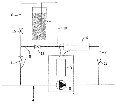
In the attached figure 1 an electrolytic device according to a preferred
embodiment of the present invention is schematically shown. In figure 1, 1
refers to a generator 1 consisting of a DC dynamo 3 and a blade wheel 2
placed in the main pipe 4. A supply pipe for the electrolytic cell 5 is
branched off from the main pipe upstream of the generator 1 and guides a
part of the water to the electrolytic cell 6. A discharge pipe for the
electrolytic cell 7 guides the water treated in the electrolytic cell back to
the main pipe 4. A supply pipe for the salt dosing device 8 branches off a
CA 02471391 2004-07-02
WO 03/055806 PCT/NL02/00873
-8-
part of the flow through the supply pipe for the electrolytic cell 5 and
guides it to the salt dosing device 9 wherein a saturated sodium chloride
solution and solid sodium chloride are present, and wherein salt is taken up
in the water. Discharge pipe for the salt dosing device 10 guides the salt
containing water back to the supply pipe for the electrolytic cell 5. In
figure
1, 11 and 12 refer to non-return valves and constrictions, respectively.
Figure 2 illustrates an embodiment of the electrolytic cell wherein the
electrolytic cell is realised as a so-called membrane electrolytic cell. Here
a
cation selective membrane 13, preferably a fluorine halogen type
membrane such as NAVION which is active chlorine resistant, is placed
between cathode 14a and the anode 14b of the electrolytic cell 6 to shield
the anode reactions from the cathode reactions.
When a membrane electrolytic cell is used, the cathode flow can even be
discharged separately and be mixed with the main flow. In that case
softening has to take place using ion exchanger resin.
When the generator does not function sufficiently, or when no or insuf-
ficient salt is supplied to the water the current to the electrodes will
strongly drop. This can be detected via a diode circuit which for instance is
able to actuate an alarm light on the system.
At a flow rate of 1000 I/h of drinking water, the generator will produce a
current of approximately 0.2-0.4 ampere, which is enough to eventually
obtain a content of 0.2 to 0.4 mg/I of active chlorine in the water. The
device is designed such that 10 I/h of water is guided through the,
electrolytic cell and approximately 100 mI/h of water is guided through the
salt dosing device. The salt dosing device contains water fully saturated
with salt and thus contains approximately 300 g/I of salt. The 100 ml/h of
water running through the salt vessel, will take up salt in a quantity of up
to 300 g/I. This salt containing water is mixed with the rest of the 10 I/h
CA 02471391 2004-07-02
WO 03/055806 PCT/NL02/00873
-9-
which is guided through the electrolytic cell so that the feeding for the
electrolytic cell will eventually contain approximately 3 g/l of salt. This
results in a conductivity of approximately 6 mS/cm which is sufficient for a
well running electrolysis process. With this conductivity a current density
of approximately 2 A/dm2 can be achieved at a voltage of approximately 5
volt. The necessary electrode surface then is approximately 0.2 dm2 for a
current of 0.4 A. The salt content of the main flow will as a result even-
tually only increase with approximately 30 mg/I. The required energy
production by the generator has to be approximately 2 W. Starting from an
efficiency of 33% of the generator, 6 W of energy will be abstracted from
the water. This corresponds to a pressure drop of 2.2 mwk. In an average
household approximately 100 I/day of hot water is used. When the salt
content increases with 30 mg/I the use of salt will therefore be 3 g/day, or
approximately 1 kg per year. Replacing the salt in a vessel of 1 .5 liter once
annually then is more than sufficient.