Note: Descriptions are shown in the official language in which they were submitted.
CA 02471508 2010-04-06
24280-54
1
Data transmission system
Field of the invention
The invention relates to a system for transmission of data
between drilling equipment and remote location means.
The invention further relates to a drilling equipment.
Background of the invention
Rock drilling equipment may be used in a number of
applications, for example in tunnelling, underground mining,
rock reinforcement and raise boring.
The equipment used in these applications are big, complex and
often very expensive. Further, the equipment often work in
exposed environments with tasks that in short time give rise
to wear and limited functionality.
Therefore this equipment require regularly service and
control. Rock drilling equipment often has an internal
computerised control system that among other collect status
information for a number of functions. This status information
may for example comprise oil temperatures, hydraulic
pressures, drilling rate etc. The control system may further
create event and error logs in order to enable subsequent
analysis of what has happened and when. The control system may
also collect run statistics.
The status information is retrieved by docking the rock
drilling equipment to a service computer or connecting an
instrument to the drilling equipment, whereby the status
CA 02471508 2004-06-22
WO 03/058030 PCT/SE03/00038
2
information is read off. The drilling equipment may also be
connected to a local wireless network at a work site, for
example a mine, which enables wireless transmission of the
status information to an equipment service centre.
The retrieved status information may be used by the service
personnel in the service centre to determine needed service.
The retrieved information may further be used by the
manufacturers service personnel, remotely located, preferably
at the manufacturers premises, to perform analysis that may
aid further development of the equipment and determine needs
for control system updates and/or replacement of parts. The
owner of the equipment may also use the status information in
work planning and follow-ups. Another use of the status
information is to enable a leasing company to charge for
actual use of the equipment.
A problem with existing systems, however, is that it may take
a long time for the remotely located parts to get access to
the status information, with the direct consequence that the
equipment may not be used in an optimal way, and a risk that
the status information is obsolete once it arrives to the
remote location.
A further problem is that the retrieved status information
requires specially designed tools that often are very
expensive in order to perform the analysis.
Thus there exists a need to provide a system that allows quick
access to status information for a remotely located part, and
that further provides the status information in a way that
obviates the need for specially designed tools.
CA 02471508 2010-04-06
24280-54
3
Summary of the invention
It is an object of the present invention to provide a system
for transmission of data between drilling equipment and remote
location means that solves the above mentioned problems.
It is a further object of the present invention to provide
drilling equipment for use in a system for transmission of
data between drilling equipment and a remote location that
solves the above mentioned problems.
The system for transmission of data between drilling equipment
and remote location means comprises (first) server means, in
communication with the drilling equipment, arranged to extract
data from the drilling equipment and convert this data to a
format suitable for presentation to a user at the remote
location by means of a general purpose program, and which
(first) server means is arranged to be connected to the
communication system, such that the remote location means and
the (first) server means may communicate via the communication
system.
This enables easy access of status information for a user at a
remote location and without a need for expensive and specially
designed tools.
The system may utilise a standardised data communication
method to communicate data between the drilling equipment and
CA 02471508 2004-06-22
WO 03/058030 PCT/SE03/00038
4
the remote location means. This gives a system that is easily
implemented, for example in an existing infra structure.
Further, utilising a standardised data communication method
for communication between the remote location and the drilling
equipment provides an inexpensive and simple way to implement
communication between drilling equipment and remote location
means.
The standardised data communication method may for example be
Ethernet or Token ring. These are well known methods and
provide an inexpensive way to implement remote control of
drilling rigs.
The general purpose program may be a web browser. This allows
that free and wide spread software may be used to retrieve
data from the drilling equipment at the remote location.
The (first) server means may be integrated in the drilling
equipment, and may further be connected to a modem for
enabling communication with the remote location means. This
enables direct communication between the drilling equipment
and the remote location means. This allows for a user at the
remote location to always have the opportunity to retrieve
valid status information.
The system may further comprise second server means, located
near the drilling equipment, and arranged to receive status
information from the first server means. The second server
means may further be arranged to receive data from the first
server means at regular intervals and/or at initiation by
either of the server means.
This enables that reasonably "fresh" status information always
is available for a user at a remote location independent of if
the drilling equipment is disconnected from the system.
CA 02471508 2011-11-10
24280-54
Further the use of second server means allow centralisation of
status information for any number of drilling equipment.
The transmitted data may constitute status information, for example
consisting of one or more of the group: oil temperatures, hydraulic pressures,
5 drilling rates, event and error logs and run statistics, video and/or sound
data.
The system may be arranged to authenticate the user prior to
presenting data to the user. This prevents unauthorised persons from accessing
the drilling equipment.
The system may be arranged to transmit data from the remote
location means to the first server means. This enables the possibility to
supply
e.g. new software to a control system of the drilling equipment.
In accordance with a broad aspect of the invention, there is
provided a system, for transmission of data between drilling equipment and
remote location means arranged to be connected to a communication system,
wherein the system comprises first server means, in communication with the
drilling equipment, arranged to extract data from the drilling equipment and
convert this data to a format suitable for presentation to a user at the
remote
location by means of a general purpose program, and which first server means
is
arranged to be connected to the communication system, such that the remote
location means and the first server means may communicate via the
communication system, characterised in that the first server means is
integrated
in the drilling equipment.
According to another aspect of the present invention, there is
provided drilling equipment, comprising server means integrated in the
drilling
equipment and in communication with the drilling equipment to extract data
from
the drilling equipment and convert this data to a format suitable for
presentation
to a user at a remote location by means of a general purpose
CA 02471508 2011-11-10
24280-54
5a
program, and which server means is arranged to be connected to a
communication system, such that remote location means and the server means
may communicate via the communication system.
Brief description of the drawings
Fig. 1 shows a control system in a drilling equipment.
Fig. 2 shows an embodiment of the present invention.
Fig. 3 shows another embodiment of the present invention.
Fig. 4 shows yet another embodiment of the present invention.
Detailed description of preferred embodiments
Fig. 1 depicts an example of the structure of a control system 1 of a
rock drilling equipment. The control system uses a CAN bus 2 (Controller Area
Network), which is a two wire serial bus, suitable for use in particularly
exposed
environments. A MMI-interface 3, used by an operator to communicate with the
control system, is connected to the bus. The control system also includes a
central unit 4 connected to the bus that controls and supervises the system. A
number of 1/0-units 5,
CA 02471508 2004-06-22
WO 03/058030 PCT/SE03/00038
6
6, 7 are connected to the bus for communication with different
parts of the rock drilling equipment. These I/O-units 5, 6, 7
may for example be used to provide control signals to the
means that control movement of the equipment. These means may
constitute of engines controlling advances of the equipment,
or, when the rock drilling equipment comprises one or more
drilling booms, control of the movement and function of the
drilling booms.
A set of sensors may further be connected to the I/O-units.
These sensors provide information, such as oil temperatures,
drilling progress, position of the drilling booms etc., to the
control system.
The central unit continuously supervises the system and
collects work statistics and creates event and error logs.
This collected and created status information may be retrieved
by service personnel by logging on to the equipment or
connecting a separate unit to the equipment. Alternatively,
the equipment may be connected to a local wireless system,
whereby the status information may be transmitted to a service
center to allow service personnel to check the status of the
equipment.
The retrieved information may further be distributed to the
manufacturer's service personnel, located at the
manufacturer's premises, to allow analysis that may aid
further development of the equipment and determine needs for
control system updates and/or replacement of parts. The owner
of the equipment may also use the status information in work
planning and follow-ups. Another use of the status information
CA 02471508 2004-06-22
WO 03/058030 PCT/SE03/00038
7
is to enable a leasing company to charge for actual use of the
equipment.
It is an object of the invention is to facilitate access to
the status information from a remote location.
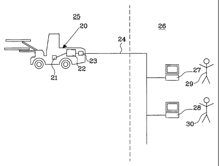
Fig. 2 shows a first embodiment of the invention. A drilling
equipment 20, comprising a control system, 21 is shown. The
drilling equipment further comprises a server 22, connected to
the control system 21 and connected to means 23 for enabling
connection of the drilling equipment to a communication system
24, extending from a work site 25 located in a first country,
to a remote location 26, for example a manufacturers service
center, located in a second country. At the remote location
26, means, such as office computers 27, 28, are operated by
operators 29, 30.
The server 22 preferably is a web server, supporting the HTTP
protocol(Hypertext Transfer Protocol, which is a commonly
known protocol for communication between web servers and web
browsers), and includes means, such as a program, to convert
status information to a format suitable for viewing by a web
browser. The server extracts status information from the
control system and converts this information to for example
HTML (Hyper Text Markup Language) or XML (Extensible Markup
Language) pages.
The status information may, as described above, constitute of
oil temperatures, hydraulic pressures, drilling rates, event
and error logs, run statistics etc.
A person 29, 30, working at the remote location 26 and wishing
to retrieve status information from the drilling equipment 20
CA 02471508 2004-06-22
WO 03/058030 PCT/SE03/00038
8
starts a web browser application on his/her computer 29, 30
and enters a URL (Uniform Resource Locator) for the server 22
in the drilling equipment 20. The web browser application then
communicates with the server 22 and presents a web page to the
user 29, 30 wherefrom desired status information may be
downloaded.
The present invention thus enables easy access of status
information for a user at a remote location and without a need
for expensive and specially designed tools. For example, a
lease company will consequently always be able to invoice
customers for actual use of rented equipment. The invention
further has the advantage that the retrieved status
information easily can be copied to other programs, such as
spreadsheets, for statistical analyse.
When the user first enters the web page of the drilling
equipment the user 29, 30 preferably must be authenticated by
entering a password to get access to the server 22, thus
preventing unauthorised persons to access the drilling
equipment. This is particularly important when the system also
is used for transmission of data to the drilling equipment, as
will be described below.
The communication system 24 preferably is an Ethernet network,
and at least parts of it may constitute parts of the Internet.
Ethernet is a common standardized method used for data
transmission over the Internet and in different computer
environments such as offices. Instead of forming part of the
Internet, the Ethernet link between the drilling equipment and
the remote location may constitute part of an Intranet for
e.g. a mining company. It shall, however, be understood that
other methods than Ethernet for communicating data may be used
as well.
CA 02471508 2004-06-22
WO 03/058030 PCT/SE03/00038
9
The embodiment in fig. 2 requires that the server 22 is in
continuous communication with the communication system 24 in
order to always admit access to the status information
collected by the server 22. This might, however, be difficult
in work sites that lack local wireless communication systems,
and where the drilling equipment must be physically connected
to a node in the communication system.
In an alternative embodiment, shown in fig. 3, the status
information collected by the server 22 is therefore
periodically transmitted to a second server 40 in a local area
network 41. In this case, the second server 40 has a fixed
connection to the communication system and a URL. This enables
that reasonably "fresh" status information always is available
for a user 29, 30 at a remote location 26. Further, the server
40 may comprise status information for any number of, or all
of the server equipped equipment at the work site, since there
might be several equipment at the work site arranged with a
server according to the present invention. The transmission to
the server means may be carried out in a number of ways. For
example, both the server 22 and the server 40 may comprise a
connection to a respective modem 42, 43. The modems 42, 43 may
be arranged to allow wireless communication. In this way the
status information may be transmitted at regularly intervals
to the server 40. Alternatively, the status information may be
transmitted when a substantial change in the operation of the
drilling equipment has occurred. The transmission may be
initiated by either of the two servers. For example, the
server 40 may initiate a transfer when a user 29, 30 at a
remote location requests status information for a particular
drilling equipment 20.
In another embodiment, shown in fig. 4, the office computer 50
is equipped with a modem 51, thus enabling direct
CA 02471508 2004-06-22
WO 03/058030 PCT/SE03/00038
communication between the drilling equipment 20 and the office
computer. This allows for a user at the remote location to
always have the opportunity to retrieve valid status
information.
5 The server means in the drilling equipment in fig. 3 and 4 may
of course as well be connected to means for enabling
connection of the drilling equipment to a communication system
as in the embodiment described in fig. 2. In this way, the
drilling equipment in fig. 3 and 4 comprises the functionality
10 of the drilling equipment in fig. 2 as well.
In yet another alternative embodiment the drilling equipment
only has capabilities to transfer the status information in
its original format to a local network at the work site,
whereby the server means performing the status information
conversion is centrally placed at the work site for collecting
and converting status information for one or more equipment at
the work site, and which server means is arranged to
communicate with remote location means, such as an office
computer, via a modem and/or a communication system.
The above described embodiments have been described with only
one remote location. There might, of course, be several remote
locations having contemporary access to the drilling
equipment, for example manufacturers premises, a leasing
company and customers main office as well as customers local
offices.
Since different persons with different needs accesses the
drilling equipment it is preferred that, in order to get
access to the status information, the user must enter a
password and/or an identity. This allows that only subsets of
the information may be shown to a specific user. For example,
if a user is only interested in failure reports, his or her
CA 02471508 2004-06-22
WO 03/058030 PCT/SE03/00038
11
interface may be set to only show the information of interest.
The information transmitted and shown to a specific user may
also be dependent on the capacity of the user's terminal. If
the user only has access to a PDA (Personal Digital Assistant)
with a rather limited bandwidth, the user may use a particular
identity when using this terminal, enabling that only a subset
of the information may be transmitted to it.
Apart from the above described status information, the server
22 may also make other data available for an external user.
For example, the drilling equipment may be provided with a
camera (not shown) and/or a microphone (not shown). This is
particularly suitable for remotely controlled equipment for
enabling convenient supervision means. The information from
the camera and/or microphone may however also be collected by
the server and arranged to be presented on the web page. It is
thus possible to allow for example service personnel in
another country to view and listen to the working equipment
via an ordinary computer with a web browser. This might be
particularly useful when the equipment exhibits a malfunction,
for which the local service personnel cannot identify the
source and an expert from the manufacturer must be consulted,
since this audio and video information may be enough for the
expert to solve the problem and thus avoid an expensive
journey to a far away mine or the like.
In yet another embodiment of the present invention, the system
further is arranged to enable transmission of data to the
drilling equipment as well as from it. A problem with the
presently used systems is that when a manufacturer of drilling
equipment releases a new software version for a control
system, this software must be stored on a code memory board
that has to be hand carried to the equipment and physically
CA 02471508 2004-06-22
WO 03/058030 PCT/SE03/00038
12
plugged into the equipment in order to perform an update of
the control system. At the best the new software may be
supplied to local service personnel in the particular country
in digital form and only has to be hand carried from there on,
which still might be several hundred kilometres. At the worst,
a person has to physically carry the code memory board half
around the world in order to make the new software available
in the drilling equipment. This manual handling is a severe
disadvantage and may result in substantial travel costs for
the manufacturer. The present invention overcomes this
problem.
The server in this case preferably also includes an FTP-
server, and is thus capable of file transfer with the commonly
known FTP-protocol (File Transfer Protocol). In this case, the
web page in the server may include links to an upload area in
the server. This possibility to upload data to the drilling
equipment enables the possibility to supply new software to
the control system of the drilling equipment. The uploaded
software is preferably stored in a dedicated location in the
memory of the drilling equipment so that the actual
replacement can be initiated and supervised by local service
personnel that are able to restore the system if the new
software malfunctions. In this embodiment, it is particularly
important that an uploading user must identify him/her so that
upload of unauthorized, possible erroneous, software is
avoided.
The above described embodiment is of course not limited to
upload of new software for the control system, but other data,
such as function parameter settings and/or personal settings
of an operator, may be uploaded as well.
CA 02471508 2004-06-22
WO 03/058030 PCT/SE03/00038
13
The invention has been described as converting the status data
to a format suitable for viewing by a web browser. The status
data may, however, also be converted to any other format
suitable for a general purpose program that is available to
the public and arranged to run on a standard computer
platform.