Language selection

Search

Patent 2471684 Summary

Third-party information liability

Some of the information on this Web page has been provided by external sources. The Government of Canada is not responsible for the accuracy, reliability or currency of the information supplied by external sources. Users wishing to rely upon this information should consult directly with the source of the information. Content provided by external sources is not subject to official languages, privacy and accessibility requirements.

Claims and Abstract availability

Any discrepancies in the text and image of the Claims and Abstract are due to differing posting times. Text of the Claims and Abstract are posted:

  • At the time the application is open to public inspection;
  • At the time of issue of the patent (grant).
(12) Patent Application: (11) CA 2471684
(54) English Title: END-WISE CONNECTION OF SECOND CHIMNEY COMPONENTS AND METHOD THEREFOR
(54) French Title: JOINT DE RACCORDEMENT DE DEUX ELEMENTS DE CHEMINEE ET METHODE CONNEXE
Status: Deemed Abandoned and Beyond the Period of Reinstatement - Pending Response to Notice of Disregarded Communication
Bibliographic Data
(51) International Patent Classification (IPC):
  • F23J 13/04 (2006.01)
  • E04F 17/02 (2006.01)
(72) Inventors :
  • GAGNE, BENOIT (Canada)
(73) Owners :
  • CHEMINEE LINING.E INC.
(71) Applicants :
  • CHEMINEE LINING.E INC. (Canada)
(74) Agent: LAVERY, DE BILLY, LLP
(74) Associate agent:
(45) Issued:
(22) Filed Date: 2004-06-18
(41) Open to Public Inspection: 2004-12-18
Availability of licence: N/A
Dedicated to the Public: N/A
(25) Language of filing: English

Patent Cooperation Treaty (PCT): No

(30) Application Priority Data:
Application No. Country/Territory Date
2,432,703 (Canada) 2003-06-18

Abstracts

English Abstract


A joint assembly for end-wise connection of two chimney components wherein
each component has an open end section with a flanged extremity. The
assembly includes an inner tubular collar having one end insertable in one end
section of a first chimney component and an opposite end insertable in one end
section of a second chimney component. A tubular band is mounted exteriorly
to the collar. The flange extremity of the first chimney component is
connected
to the flange extremity of the second chimney component so as to secure the
end sections to one another with the collar and the tubular band mounted
therein.


Claims

Note: Claims are shown in the official language in which they were submitted.

WHAT IS CLAIMED IS:
1. A joint assembly for end-wise connection of a first and a
second chimney components, each one of the first and second chimney
components having an open end section with a flanged extremity, comprising:
an inner tubular collar having one end insertable in the
open end section of the first chimney component and an opposite end
insertable in the open end section of the second chimney component; and
connection means fixedly securing the flanged extremity of
the first chimney component to the flanged extremity of the second chimney
component to secure said end section of the first chimney component to said
end section of the second chimney component with said inner tubular collar.
2. The joint assembly as defined in claim 1, wherein said
connection means comprise sealing means for adhesively mounting said
flanged extremities to one another.
3. The joint assembly as defined in claim 2, wherein said
sealing means comprise a silicone layer between said flanged extremities.
4. The joint assembly as defined in any one of claims 2 and
3, wherein said connection means further comprise an assembly band mounted
exteriorly to said flanged extremities sealed to one another.
5. The joint assembly as defined in claim 4, wherein said
connection means further comprise a pair of attaching bands mounted
exteriorly to said assembly band.

6. The joint assembly as defined in claim 4, wherein said
assembly band displays a V-shaped mid section receiving the flanged
extremities sealed to one another.
7. The joint assembly as defined in claim 6, further
comprising a silicone material in said V-shaped mid-section.
8. The joint assembly as defined in claim 5, wherein said
attaching bands are welded to said assembly band.
9. The joint assembly as defined in any one of claims 1 to 8,
further comprising a tubular band mounted exteriorly to said inner tubular
collar,
said connection means fixedly securing the flanged extremity of the first
chimney component to the flanged extremity of the second chimney component
so as to secure said end section of the first chimney component to said end
section of the second chimney component with said inner tubular collar and
said tubular band mounted therein.
10. The joint assembly as defined in claim 9, wherein said
tubular band is made in ceramic fiber.
11. The joint assembly as defined in any one of claims 9 and
10, further comprising adhesive means for fixing said tubular band between
said inner tubular collar and said end sections.
12. The joint assembly as defined in any one of claims 1 to 11,
wherein one of the ends of said inner tubular collar is welded to an inner
wall of
the open end section of one of said first and second chimney components.

13. The joint assembly as defined in any one of claims 1 to 12,
wherein said first and second chimney components have an inner diameter
slightly greater than an outer diameter of said inner tubular collar.
14. The joint assembly as defined in claim 13, wherein said
open end sections of said first and second chimney components have an inner
diameter greater than the inner diameter of said first and second chimney
components.
15. A method for end-wise connection of a first and a second
chimney components in a joint assembly, each one of the first and second
chimney components having an open end section with a flanged extremity,
comprising the steps of:
a) inserting an inner tubular collar in the open end section of the
first chimney component;
b) applying a sealant circumferentially on the flanged extremity of
the open end section of the second chimney component; and
c) moving the first chimney component in engagement with the
second chimney component.
16. The method of claim 15, further comprising after step a)
the step of welding an upper end of the inner tubular collar to an inner wall
of
the open end section of the first chimney component.
17. The method according to any one of claims 15 and 16,
further comprising, prior to step b) the steps of inserting a tubular band
between the inner tubular collar and the open end section of the first chimney
component and of fixing the tubular band therein.

18. The method according to any one of claims 15 to 17,
further comprising a step d) of securing the connection with an assembly band.
19. The method according to claim 18, wherein said step d)
comprises providing an assembly band with a V-shaped mid section, mounting
exteriorly to the assembly band a pair of attaching bands, depositing a
silicone
material in the V-shaped mid section of the assembly band; placing the
assembly band with the attaching bands to receive the first and second flanged
extremities sealed together.

Description

Note: Descriptions are shown in the official language in which they were submitted.


CA 02471684 2004-06-18
1
TITLE OF THE INVENTION
End-wise connection of second chimney components and
method therefor
FIELD OF THE INVENTION
[0001] The present invention relates to a joint assembly for end-wise
connection of two chimney components.
BACKGROUND OF THE INVENTION
[0002] Chimney systems permit the exhaust of combustion gases,
under positive, negative or neutral pressure, emanating from a variety of
appliances including, but not limited to, diesel engine and gas turbine
exhausts,
industrial oven exhausts, restaurant grease ducts, boilers, incinerators, etc.
(0003] The various components of known factory-built positive
pressure chimney systems include lengths, expansion joints, tees, elbows, etc.
These components typically have a flange-to-flange end at there joining point.
These flanges are joined together by aligning the flanges together. They are
then joined together by means of a v-shaped assembly band, which is clamped
around the flanges of both parts. A sealant is applied in the groove of the v-
band before it is clamped to the flanges.
[0004] There is still room in the art for a joint assembly for end-wise
connection of two chimney components and a method therefor.

CA 02471684 2004-06-18
2
SUMMARY OF THE INVENTION
(0005) More specifically, there is provided a joint assembly for end-
wise connection of a first and a second chimney components, each one of the
first and second chimney components having an open end section with a
flanged extremity, comprising:
an inner tubular collar having one end insertable in the open end section
of the first chimney component and an opposite end insertable in the open end
section of the second chimney component; and
connection means fixedly securing the flanged extremity of the first
chimney component to the flanged extremity of the second chimney component
to secure the end section of the first chimney component to the end section of
the second chimney component with the inner tubular collar.
(0006) There is further provided a method for end-wise connection of
a first and a second chimney components in a joint assembly, each one of the
first and second chimney components having an open end section with a
flanged extremity, comprising the steps of:
a) inserting an inner tubular collar in the open end section of the first
chimney component;
b) applying a sealant circumferentially on the flanged extremity of the
open end section of the second chimney component; and
c) moving the first chimney component in engagement with the second
chimney component.
(0007) Other objects, advantages and features of the present
invention will become more apparent upon reading of the following non-
restrictive description of embodiments thereof, given by way of example only
with reference to the accompanying drawings.

CA 02471684 2004-06-18
3
BRIEF DESCRIPTION OF THE DRAWINGS
(0008] In the appended drawings:
(0009] Figure 1 is a elevational view showing a joint assembly prior
to an interconnection of two chimney components;
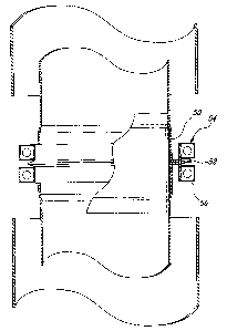
(0010] Figure 2 is an elevational view showing the joint assembly of
Figure 1, with the two chimney components interconnected;
(0011] Figure 3 is an enlarged view of an assembly band and of
attaching bands securing a joint assembly; and
(0012] Figure 4 is an illustration of one half of an attaching band as
used in Figure 3.
DESCRIPTION OF EMBODIMENTS OF THE INVENTION
(0013] Referring to Figure 1, there is shown a joint assembly,
generally denoted 10, for connecting two chimney components, identified as A
and B. In the embodiment illustrated, the two chimney components A and B
are two lengths of a double wall chimney construction consisting of an outer
wall 12 and an inner wall 14 for chimney component A, and an outer wall 16
and an inner wall 18 for chimney component B.
(0014] The inner wall 14, 18 of each chimney component defines an
open end section 20, 22 having a diameter slightly greater than a diameter of
the remaining portion of the wall. Each end section 20, 22 has a flanged
extremity 24, 26.

CA 02471684 2004-06-18
4
(0015] The joint assembly 10 comprises an inner tubular collar 28
having one end 30 insertable in the open section 20 of the chimney component
A and an opposite end 32 insertable in the end section 22 of chimney B (as
indicated by the arrows 34).
(0016 In the cases of high temperature applications, a tubular band
36 made of ceramic fiber may be circumferentially and exteriorly mounted over
part of an outer wall of the collar 28.
(0017 The end-wise connection of chimney component A to
chimney component B will now be described. First, the collar 28 is inserted in
the end connection 20 of chimney component A. The upper end 30 of the
collar is welded, for example seam welded or spot-welded, to the inner wall of
the end section 20. When a tubular band 36 is used, it is then inserted
between the collar 28 and the end section 20 and is fixed therein by means of
an adhesive 40. Subsequently, a sealant 42, such as a silicone, is applied
circumferentially on the flanged extremity 26 of the chimney component B.
Chimney component A with the joint assembly 10 is then moved as indicated
by arrows 34 to engage the chimney component B.
(0018 Referring to Figure 2, where the two chimney components A
and B are shown engaged to one another, the connection is further secured by
means of an assembly band 50,. having a V-shaped mid section 52, to which a
pair of attaching bands 54 and 56 are mounted exteriorly. The pair of
attaching
bands 54 and 56 is welded to the assembly band 50. A silicone material 58 is
deposited in the V-shaped section 52 of the assembly band 50. The assembly
band 50 and attaching bands 54 and 56 are placed in a manner that the
flanged extremities 24, 26 sealed to one another are received within the mid

CA 02471684 2004-06-18
section 52 of the assembly band to which they are further sealed due to the
adhesive 58.
[0019] Figure 4 illustrates the construction of the extremities 60 and
62 of an attaching band so that a full ring may be formed.
[0020] Although the present invention has been described
hereinabove by way of embodiments thereof, it may be modified, without
departing from the nature and teachings of the subject invention as defined in
the appended claims.

Representative Drawing
A single figure which represents the drawing illustrating the invention.
Administrative Status

2024-08-01:As part of the Next Generation Patents (NGP) transition, the Canadian Patents Database (CPD) now contains a more detailed Event History, which replicates the Event Log of our new back-office solution.

Please note that "Inactive:" events refers to events no longer in use in our new back-office solution.

For a clearer understanding of the status of the application/patent presented on this page, the site Disclaimer , as well as the definitions for Patent , Event History , Maintenance Fee  and Payment History  should be consulted.

Event History

Description Date
Application Not Reinstated by Deadline 2010-06-18
Time Limit for Reversal Expired 2010-06-18
Deemed Abandoned - Failure to Respond to Maintenance Fee Notice 2009-06-18
Inactive: Abandon-RFE+Late fee unpaid-Correspondence sent 2009-06-18
Inactive: Payment - Insufficient fee 2006-10-03
Inactive: Office letter 2006-10-03
Letter Sent 2006-10-03
Inactive: Entity size changed 2006-10-03
Inactive: Corrective payment - s.78.6 Act 2006-09-20
Reinstatement Requirements Deemed Compliant for All Abandonment Reasons 2006-09-20
Deemed Abandoned - Failure to Respond to Maintenance Fee Notice 2006-06-19
Inactive: IPC from MCD 2006-03-12
Letter Sent 2005-06-20
Inactive: Single transfer 2005-06-09
Application Published (Open to Public Inspection) 2004-12-18
Inactive: Cover page published 2004-12-17
Inactive: First IPC assigned 2004-11-26
Inactive: Courtesy letter - Evidence 2004-08-03
Inactive: Filing certificate - No RFE (English) 2004-07-27
Filing Requirements Determined Compliant 2004-07-27
Application Received - Regular National 2004-07-26

Abandonment History

Abandonment Date Reason Reinstatement Date
2009-06-18
2006-06-19

Maintenance Fee

The last payment was received on 2008-06-12

Note : If the full payment has not been received on or before the date indicated, a further fee may be required which may be one of the following

  • the reinstatement fee;
  • the late payment fee; or
  • additional fee to reverse deemed expiry.

Patent fees are adjusted on the 1st of January every year. The amounts above are the current amounts if received by December 31 of the current year.
Please refer to the CIPO Patent Fees web page to see all current fee amounts.

Fee History

Fee Type Anniversary Year Due Date Paid Date
Application fee - small 2004-06-18
Registration of a document 2005-06-09
MF (application, 2nd anniv.) - standard 02 2006-06-19 2006-05-24
2006-09-20
Reinstatement 2006-09-20
MF (application, 3rd anniv.) - standard 03 2007-06-18 2007-06-18
MF (application, 4th anniv.) - standard 04 2008-06-18 2008-06-12
Owners on Record

Note: Records showing the ownership history in alphabetical order.

Current Owners on Record
CHEMINEE LINING.E INC.
Past Owners on Record
BENOIT GAGNE
Past Owners that do not appear in the "Owners on Record" listing will appear in other documentation within the application.
Documents

To view selected files, please enter reCAPTCHA code :


To view images, click a link in the Document Description column. To download the documents, select one or more checkboxes in the first column and then click the "Download Selected in PDF format (Zip Archive)" or the "Download Selected as Single PDF" button.

List of published and non-published patent-specific documents on the CPD .

If you have any difficulty accessing content, you can call the Client Service Centre at 1-866-997-1936 or send them an e-mail at CIPO Client Service Centre.


Document
Description 
Date
(yyyy-mm-dd) 
Number of pages   Size of Image (KB) 
Abstract 2004-06-17 1 17
Description 2004-06-17 5 161
Claims 2004-06-17 4 120
Drawings 2004-06-17 3 43
Representative drawing 2004-11-21 1 7
Filing Certificate (English) 2004-07-26 1 158
Courtesy - Certificate of registration (related document(s)) 2005-06-19 1 114
Reminder of maintenance fee due 2006-02-20 1 111
Courtesy - Abandonment Letter (Maintenance Fee) 2006-10-01 1 175
Notice of Reinstatement 2006-10-02 1 166
Reminder - Request for Examination 2009-02-18 1 117
Courtesy - Abandonment Letter (Maintenance Fee) 2009-08-12 1 174
Courtesy - Abandonment Letter (Request for Examination) 2009-09-23 1 165
Correspondence 2004-07-26 1 26
Fees 2006-05-23 1 44
Correspondence 2006-10-02 1 17
Fees 2006-09-19 1 43
Fees 2007-06-17 1 45
Fees 2008-06-11 1 46