Note: Descriptions are shown in the official language in which they were submitted.
CA 02472144 2004-06-30
WO 03/065567 PCT/DE03/00172
Circuit arrangement for use in a wind energy
installation
The invention relates to a circuit arrangement which is
intended in particular for use in a variable rotation
speed wind energy installation, comprising a double-fed
asynchronous generator, an additional resistor and a
converter.
Circuit arrangements such as these which are intended
for use in variable speed wind energy installations are
widely used in practice and are thus prior art by
virtue of obvious prior use. However, it has been found
to be disadvantageous when using double-fed
asynchronous machines (DASM) that these are
disconnected from the network in the event of a network
short circuit at the medium-voltage level. This means
that it is not possible to achieve the desired network
stabilization by means of a wind power installation
which is operated with a double-fed asynchronous
machine.
In the past, the necessary network stabilization has
thus been achieved by the network operators by means of
conventional power stations. Owing to the rapidly
increasing number of wind power installations and the
rapidly rising power level associated with them, which
has now reached the magnitude of conventional power
stations, the requirements for wind power installations
must, however, be matched to those of conventional
power stations. In particular, permanent network
coupling is being increasingly demanded in order that
the wind energy installation can set up the network
again, and can stabilize it, once a medium-voltage
network short circuit has ended.
CA 02472144 2009-10-05
- 2 -
The invention is based on the object of providing a
circuit arrangement for use in wind power installations
having an asynchronous machine, by means of which more
stringent requirements for modern wind power
installations, in particular with regard to network
stabilization, can be satisfied.
According to an aspect of the present invention there
is provided circuit arrangement for use in a variable
rotation speed wind energy installation, the circuit
arrangement comprising a double-fed asynchronous
generator, an additional resistor and a converter,
wherein the additional resistor can be controlled by
means of a switch such that the converter can be at
least temporarily disconnected in the event of a
network short circuit, in order for the rotor current
to be taken over in the short term by means of the
additional resistor, and can be connected to the
network again for active injection of a short-circuit
current after the rotor short-circuit current has
decayed.
According to another aspect of the present invention
there is provided circuit arrangement for use in a
variable rotation speed wind energy installation
comprising a double-fed asynchronous generator, an
additional resistor and a converter, wherein the rotor
inverter is switched off when the network voltage
rises, and the overcurrent is passed through the
controllable resistor and, once the overcurrent has
decayed, the controlled resistor is switched off and
the rotor inverter actively carries the rotor current.
Thus, according to the invention, a circuit arrangement
is proposed in which the additional resistor can be
controlled by means of a high-speed switch such that
the converter can be at least temporarily switched off
in the event of a network short circuit, in order for
CA 02472144 2009-10-05
- 2a -
the rotor current to be taken over in the short term by
means of the additional resistor, and can be connected
to the network again for active injection of a short-
circuit current after the rotor short-circuit current
has decayed.
This allows the more stringent network requirements for
network stabilization during operation of the wind
power installation equipped with an asynchronous
generator to be optimally satisfied, because no
disconnection from the network takes place in this case
in the event of a network short circuit at the medium-
voltage level. For this purpose, for example, an
additional resistor which is in the form of a
controllable load resistor or a crow bar which is
equipped with the additional resistor for this purpose
was inserted in the rotor circuit to draw the rotor
short circuit energy when a network short circuit
occurs, and which is then switched off once the short-
circuit current has decayed. The load resistor is
controlled by a switch which, in particular, can be
CA 02472144 2004-06-30
WO 03/065567 PCT/DE03/00172
3 -
actively switched off and is, in particular, not a
naturally commutated thyristor. The existing rotor
inverter for the four-quadrant inverter is briefly
deactivated immediately after the occurrence of the
network short circuit and is activated again after the
short-circuit equalization process has decayed, with
the threshold value advantageously being below the
rotor inverter rated current, and then feeds the
necessary power into the network during the network
short circuit and when the network voltage returns.
A modification of the present invention has been found
to be particularly advantageous in this case, in which
the circuit arrangement has two or more resistors which
can be connected dependent on one another or
independently of one another. This means that the high
rotor short-circuit current, which is frequently more
than 1000 A, can be shared between a number of
switches, since these switches which can be switched
off would have to be connected in parallel in a highly
complex manner for the total current.
A circuit arrangement having a two-point regulator for
control of the additional resistor is also particularly
advantageous since this allows very simple, high-speed
and robust control to be set up.
In this case, a further modification has been found to
be particularly expedient in which the active switch is
controlled by pulse-width modulation at a fixed clock
frequency, because this allows digital control at a
fixed clock frequency.
Furthermore, it also promises to be particularly
successful for the active switch to be controlled by a
P regulator, a PI regulator or a PID regulator. This
means that the rotor short-circuit current or the rotor
CA 02472144 2004-06-30
WO 03/065567 PCT/DE03/00172
4 -
terminal voltage can be optimally regulated when a
network short circuit takes place.
A refinement of the circuit arrangement according to
the invention is also particularly advantageous in
which in the event of a network short circuit, a
capacitive current or an inductive current is supplied
to the short circuit, since this allows the network to
be stabilized in an optimum manner depending on the
network operator requirement. A capacitive current is
normally desirable in order to supply the inductive
network loads.
It is also particularly worthwhile to prevent any
wattless component from being transmitted into the
short circuit when a network short circuit occurs since
this results in the least current being fed into the
short circuit, in order to avoid overloading existing
medium-voltage switches.
Furthermore, according to a further particularly
advantageous refinement, an additional impedance is
briefly inserted in the stator circuit in order to
limit the stator and the rotor current. The insertion
of the additional impedance as required allows the
stator current and rotor current to be limited when the
network voltage returns.
An embodiment is also particularly advantageous in
which a high-seed contactor is inserted in the stator
circuit in parallel with the additional impedance, in
order in this way to bridge the additional impedance
during normal operation, and to avoid producing losses.
Furthermore, it also promises to be particularly
successful for at least one thyristor with natural
commutation to be inserted in the stator circuit in
parallel with the resistor. Compared with switches
CA 02472144 2004-06-30
WO 03/065567 PCT/DE03/00172
- 5 -
which can be switched off actively, this results in
reduced losses during normal operation, with the costs
being lower.
Furthermore, the circuit arrangement can be designed in
a particularly advantageous manner by operating a
controlled resistor on the intermediate circuit of the
converter, because this makes it possible to save some
of the components in the crow bar, and the control for
the rotor inverter measures the rotor phase current all
the time.
Another particularly expedient refinement of the
invention is also achieved by operating a controlled
resistor both in the crow bar and in the intermediate
circuit of the converter. This allows power sharing,
and smaller individual switches can be used. Towards
the end of the equalization process for the rotor
short-circuit current, all of the rotor current is
carried, and the rotor inverter control then measures
the entire phase current.
Furthermore, a particularly advantageous embodiment of
the invention is also achieved by switching off the
rotor inverter when the network voltage returns, with
the overcurrent then being carried by the controllable
resistor, in order to actively carry the rotor current
once the overcurrent has decayed and the controlled
resistor has been switched off. This avoids the wind
energy installation from possibly being switched off
and disconnected from the network, in particular when
the network voltage returns suddenly.
The invention allows various embodiments. One of these
is illustrated in the drawing, and will be described in
the following text, in order to further explain the
fundamental principle of the invention. In the figures:
CA 02472144 2004-06-30
WO 03/065567 PCT/DE03/00172
6 -
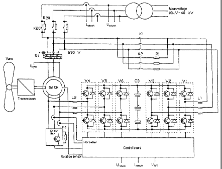
Figure 1 shows a circuit arrangement according to the
invention;
Figure 2 shows one possible short-circuit profile;
Figure 3 shows a circuit arrangement with a
controllable rotor resistance and an
additional stator resistance;
Figure 4 shows a voltage- and current-time profile
with an additional resistor;
Figure 5 shows a circuit arrangement with stronger
inverter diodes and a controllable load
resistance in the intermediate circuit.
Figure 1 shows a circuit arrangement according to the
invention. During normal operation, a switch V15, for
example an IGBT, GTO, IGCT, is switched off and the
crow bar is fully inactive. All of the rotor current
flows into a converter and is regulated by it. If a
network short circuit occurs at the medium voltage, the
full excitation of an asynchronous generator means that
it will supply an equalization short-circuit current to
the short circuit. The current is limited only by the
stray inductances of the asynchronous generator and
medium-voltage transformer, and the maximum current
reaching the following value:
I 1 .8 = Unetwork
stator Xtr + Xl + X2'
In this case, Xtr is the total stray impedance of the
transformer, Xl is the stray impedance of the stator
and X2' is the stray impedance of the rotor. In the
event of a short circuit on the medium voltage, the
maximum stray current is in practice in the order of
magnitude of up to 8 times the stator rated current.
CA 02472144 2004-06-30
WO 03/065567 PCT/DE03/00172
7 -
The rotor current is coupled by transformer action to
the stator current and also reaches up to 8 times the
rotor rated current. This high equalization current
cannot technically sensibly be carried or absorbed by
the converter. When the short circuit occurs, a rotor
inverter is switched off due to the overcurrent. The
rotor current continues to flow via freewheeling diodes
in the rotor inverter, and charges an intermediate
circuit C3. At the same time, the voltage across a
capacitor C10 in the crow bar rises. When the voltage
across the capacitor CIO reaches a limit value, the
switch V15 is switched on. A resistor R15 carries all
of the rectified rotor current, and the voltage across
the capacitor C10 falls below the voltage limit value,
so that the switch V15 is switched off. The voltage
across the capacitor C10 then rises again owing to the
rotor current, and the switch V15 is switched on again.
The rate of current change and hence also the clock
frequency are governed by L15. The clock frequency is
up to the kHz range and cannot be produced by natural
commutation of thyristors, since the maximum rotor
frequency is 15 Hz. This two-point regulation results
in a constant back e.m.f. for the rotor voltage, and
the equalization current decays in a very short time
because of the high constant back e.m.f. All of the
current is commutated from the rotor inverter to the
crow bar. The converter current is virtually zero. The
crow bar current is measured and evaluated by the
control board. The load resistance is designed for
maximum current, and the time for which the switch V15
is switched on is initially close to 100%. As the
equalization current falls, the time for which the
switch V15 is switched on becomes less and is
approximately 12% at the rotor rated current, which
corresponds to approximately 1/8 of the maximum
current. It would also be feasible to use two or more
resistors, which can be connected and disconnected
individually. When the equalization current falls below
CA 02472144 2004-06-30
WO 03/065567 PCT/DE03/00172
8 -
the rotor rated current, then the switch V15 is
switched off completely, and the rotor current
commutates back into the converter. The converter
starts to operate and provide regulation, and actively
feeds the short circuit. While the controllable
resistor is active, the network inverter can be
switched off, although simultaneous operation is also
possible. For safety reasons, a thyristor V10 is
provided in the crow bar, which automatically measures
the voltage and is triggered in the event of failure in
the switch V15 or in the event of a direct generator
short circuit. L10 prevents the current from rising
excessively fast, in order to prevent destruction of
the thyristor V10. In this case, D10 prevents rapid
discharging of a capacitor C10 through the switch V15.
The switch V15 can be controlled either directly in the
crow bar or by the control board for the converter.
Figure 2 illustrates one possible short-circuit
profile, with the dashed line representing the medium
voltage and the solid line representing the network
voltage. The short circuit occurs at the instant 0 ms.
The current immediately jumps to the maximum value and
then decays, as a result of the equalization process.
The high current is drawn by the crow bar and resistor.
When the current falls below the rotor rated current,
it is once again transferred to and controlled by the
converter. The generator is overexcited and supplies a
capacitive wattless component to the network during the
network short circuit. However, inductive current can
also be fed into the short circuit. This can be preset
freely as required. Owing to the voltage drop across
the medium-voltage transformer, the network voltage is
in the order to magnitude of about 20% of the rated
voltage. At the instant when the voltage returns, the
voltage does not rise suddenly to the rated value, but
rises over a dU/dt flank. A dynamic overcurrent occurs
in the stator and rotor as a result of the flank
CA 02472144 2004-06-30
WO 03/065567 PCT/DE03/00172
9 -
gradient of the returning network voltage and the time
constant of the generator. It must be possible for this
overcurrent to be supplied by the converter without
this leading to the rotor inverter being switched off.
If the flank gradient is too great or there is a phase
fault between the generator voltage and the returning
network voltage, then the dynamic overcurrent or
equalization current will be excessively high, and the
rotor inverter is switched off. In this case as well,
the controllable resistor briefly carries the
equalization current and, once the current has fallen
below the rotor rated current, the resistor is switched
off and the rotor inverter is once again regulated. The
controllable resistor is briefly activated during the
drop in voltage and when the voltage returns. The rotor
inverter is switched off during this time.
In the event of extremely fast voltage rise times, an
additional impedance, for example in the form of a
resistor or an inductor, can be inserted in the stator
circuit. A system such as this is illustrated in Figure
3. A contactor K20 is inserted between the medium-
voltage transformer and the generator/converter system.
A resistor R20 is connected in parallel via the
contactor K20. If a short circuit occurs, then the
contactor K20 is opened and the stator current flows
through the resistor R20.
Fig. 4 shows the voltage-time profile with an
additional resistor. The stator current is limited and
decays more rapidly than with only the regulated crow
bar. The contactor has to switch very quickly for the
resistor to be active in the event of very short
voltage drops. A back-to-back parallel-connected
thryistor switch with natural commutation may also be
used with, for example, a switching off time of 6.7 ms
at 50 Hz. This results in a high-speed switch, that has
the disadvantage of high losses, compared with the
CA 02472144 2004-06-30
WO 03/065567 PCT/DE03/00172
- 10 -
contactor solution. In Figure 4, the switch is opened
after 10 ms. The converter once again provides the
control function after the equalization process. Owing
to the additional voltage drop across the resistor, the
residual network voltage is higher than that without
any additional impedance in the stator. When the
voltage returns, the additional resistor limits the
dynamic stator current rise, thus allowing higher
voltage flanks and lower overcurrents.
The freewheeling diodes of IGBT modules are not
designed for very high pulse currents. The components
of the controlled resistor were therefore placed in the
crow bar. Figure 5 shows a circuit arrangement with
high-power freewheeling diodes. The switch V15 is
coupled directly to the intermediate circuit of the
converter, and directly regulates the intermediate
voltage. This would simplify the entire design. The
additional standard crow bar is retained for extreme
situations.
It would also be possible to completely dispense with
the crow bar. In this case, the additional resistor
must be designed for all extreme situations. In the
event of a short circuit, the rotor inverter IGBTs are
switched off, and the rotor short-circuit current flows
through the freewheeling diodes into the intermediate
circuit. If a limit value is exceeded, the additional
resistor is activated, and the short-circuit energy is
absorbed in the additional resistor. Once the short-
circuit current has decayed, the rotor inverter is
activated once again, and the additional resistor is
switched off. It is also possible to switch the
additional resistor off first of all, and to connect
the rotor inverter. Simultaneous operation of the
additional resistor and of the rotor inverter is also
possible.