Note: Descriptions are shown in the official language in which they were submitted.
CA 02472284 2008-02-25
PROTECTIVE SLEEVE FOR THREADED CONNECTIONS FOR
EXPANDABLE LINER HANGER
Background of the Invention
[003] This invention relates generally to oil and gas exploration, and in
particularto forming and
repairing wellbore casings to facilitate oil and gas exploration.
[004] During oil exploration, a wellbore typically traverses a number of zones
within a
subterranean formation. Wellbore casings are then formed in the wellbore by
radially expanding
and plastically deforming tubular members that are coupled to one another by
threaded
connections. Existing methods for radially expanding and plastically deforming
tubular members
coupled to one another by threaded connections are not always reliable or
produce satisfactory
results. In particular, the threaded connections can be damaged during the
radial expansion
process.
[005] The present invention is directed to overcoming one or more of the
limitations of the
existing processes for radially expanding and plastically deforming tubular
members coupled to
one another by threaded connections.
Summary of the Invention
[006] According to one aspect of the present invention, a method of radially
expanding and
plastically deforming a first tubular member and a second tubular member is
provided that
includes inserting a threaded end portion of the first tubular member Into an
end of a tubular
sleeve having an internal flange; inserting a threaded end portion of the
second tubular member
into another end of the tubular sleeve; threadably coupling the threaded end
portions of the first
and second tubular members within the tubular sleeve; and displacing an
expansion device
through the interiors of the first and second tubular members to radially
expand and plastically
deform portions of the first and second tubular members; wherein the internal
diameters of the
radially expanded and plastically deformed portions of the first and second
tubular members are
equal.
[007] According to another aspect of the present invention, a method of
radially expanding and
plastically deforming a first tubular member and a second tubular member is
provided that
includes inserting a threaded end portion of the first tubular member Into an
end of a tubular
sleeve; coupling the end of the tubular sleeve to the threaded end portion of
the first tubular
member; inserting a threaded end portion of the second tubular member into
another end of the
1
CA 02472284 2008-02-25
tubular sleeve; threadably coupling the threaded end portions of the first and
second tubular
member within the tubular sleeve; coupling the other end of the tubular sleeve
to the threaded
end portion of the second tubular member; and displacing an expansion device
through the
interiors of the first and second tubular members to radially expand and
plastically deform
portions of the first and second tubular members; wherein the internal
diameters of the radially
expanded and plastically deformed portions of first and second tubular members
are equal.
[008] According to another aspect of the present invention, a method of
radially expanding and
plastically deforming a first tubular member and a second tubular member is
provided that
includes inserting an end of a tubular sleeve having an external flange into
an end of the first
tubular member until the external flange abuts the end of the first tubular
member, inserting the
other end of the tubular sleeve into an end of a second tubular member,
threadably coupling the
ends of the first and second tubular member within the tubular sleeve until
both ends of the first
and second tubular members abut the external flange of the tubular sleeve, and
displacing an
expansion device through the interiors of the first and second tubular
members.
[009] According to another aspect of the present invention, a method of
radially expanding
and plastically deforming a first tubular member and a second tubular member
is provided
that includes inserting an end of the first tubular member into an end of a
tubular sleeve
having an internal flange into abutment with the internal flange; inserting an
end of the
second tubular member into another end of the tubular sleeve into abutment
with the internal
flange; coupling the ends of the first and second tubular member to the
tubular sleeve; and
displacing an expansion device through the interiors of the first and second
tubular members
to radially expand and plastically deform the ends of the first and second
tubular members;
wherein the internal diameters of the radially expanded and plastically
deformed ends of the
first and second tubular members are equal.
[0010] According to another aspect of the present invention, an apparatus is
provided that
includes a first tubular member comprising a threaded end portion; a second
tubular member
comprising a threaded end portion; and a tubular sleeve that receives,
overlaps with, and is
coupled to the threaded end portions of the first and second tubular members;
wherein the
threaded end portion of the first tubular member is threadably coupled to the
threaded end
portion of the second tubular member; wherein portions of the first and second
tubular
members are radially expanded and plastically deformed; and wherein the
internal diameters
of non-threaded portions of the radially expanded and plastically deformed
portions of the
first and second tubular members are equal.
[0011] According to another aspect of the present invention, an apparatus is
provided that
includes a first tubular member comprising a threaded end; a second tubular
member
comprising a threaded end; and a tubular sleeve that is received within,
overlaps with, and is
coupled to the threaded ends of the first and second tubular members; wherein
the threaded
2
CA 02472284 2008-02-25
end of the first tubular member is threadably coupled to the threaded end of
the second
tubular member; and wherein the threaded ends of the first and second tubular
members are
radially expanded and plastically deformed.
[0012] According to another aspect of the present invention, an apparatus is
provided that
includes a first tubular member; a second tubular member; and a tubular sleeve
that
receives, overlaps with, and is coupled to the threaded ends of the first and
second tubular
members; wherein the ends of the first and second tubular members are in
circumferential
compression and the tubular sleeve is in circumferential tension; wherein the
ends of the first
and second tubular members are radially expanded and plastically deformed; and
wherein
the internal diameters of the radially expanded and plastically deformed ends
of the first and
second tubular members are equal.
[0013] According to another aspect of the present invention, an apparatus is
provided that
includes a first tubular member comprising a threaded end portion; a second
tubular member
comprising a threaded end portion; a tubular sleeve that receives, overlaps
with, and is
coupled to the threaded end portions of the first and second tubular members;
one or more
first resilient locking members for locking the first tubular member to the
tubular sleeve; and
one or more second resilient locking members for locking the second tubular
member to the
tubular sleeve; wherein the threaded end portions of the first and second
tubular members
are in circumferential compression and the tubular sleeve is in
circumferential tension;
wherein portions of the first and second tubular members are radially expanded
and
plastically deformed; and wherein the internal diameters of radially expanded
and plastically
deformed portions of the first and second tubular members are equal.
[0014] According to another aspect of the present invention, a method of
radially expanding
and plastically deforming a first tubular member and a second tubular member
is provided
that includes inserting a threaded end portion of the first tubular member
into an end of a
tubular sleeve having an internal flange; inserting a threaded end portion of
the second
tubular member into another end of the tubular sleeve; threadably coupling the
threaded end
portions of the first and second tubular members within the tubular sleeve;
and displacing an
expansion device through the interiors of the first and second tubular members
to radially
expand and plastically deform portions of the first and second tubular
members; wherein the
internal diameter of at least one of the non-threaded portion of the first
tubular member and
the non-threaded portion of the second tubular member is equal to the internal
diameter of
the internal flange of the tubular sleeve.
[0015] According to another aspect of the present invention, a method of
radially expanding
and plastically deforming a first tubular member and a second tubular member
is provided
that includes inserting a threaded end portion of the first tubular member
into an end of a
tubular sleeve having an internal flange; inserting a threaded end portion of
the second
3
CA 02472284 2008-02-25
tubular member into another end of the tubular sleeve; threadably coupling the
threaded end
portions of the first and second tubular members within the tubular sleeve;
and displacing an
expansion device through the interiors of the first and second tubular members
to radially
expand and plastically deform portions of the first and second tubular
members; wherein,
after the radial expansion and plastic deformation, the internal diameter of
at least one of the
non-threaded portion of the first tubular member and the non-threaded portion
of the second
tubular member is equal to the internal diameter of the internal flange of the
tubular sleeve.
[0016] According to another aspect of the present invention, a method of
radially expanding
and plastically deforming a first tubular member and a second tubular member
is provided
that includes inserting a threaded end portion of the first tubular member
into an end of a
tubular sleeve having an internal flange; inserting a threaded end portion of
the second
tubular member into another end of the tubular sleeve; threadably coupling the
threaded end
portions of the first and second tubular members within the tubular sleeve;
and displacing an
expansion device through the interiors of the first and second tubular members
to radially
expand and plastically deform portions of the first and second tubular
members; wherein a
portion of the first tubular member abuts an end face of the internal flange
of the tubular
sleeve; and wherein a portion of the second tubular member abuts another end
face of the
internal flange of the tubular sleeve.
[0017] According to another aspect of the present invention, a method of
radially expanding
and plastically deforming a first tubular member and a second tubular member
is provided
that includes inserting a threaded end portion of the first tubular member
into an end of a
tubular sleeve; coupling the end of the tubular sleeve to the threaded end
portion of the first
tubular member; inserting a threaded end portion of the second tubular member
into another
end of the tubular sleeve; threadably coupling the threaded end portions of
the first and
second tubular member within the tubular sleeve; coupling the other end of the
tubular
sleeve to the threaded end portion of the second tubular member; and
displacing an
expansion device through the interiors of the first and second tubular members
to radially
expand and plastically deform portions of the first and second tubular
members; wherein the
internal diameter of at least one of the non-threaded portion of the first
tubular member and
the non-threaded portion of the second tubular member is equal to the internal
diameter of
the internal flange of the tubular sleeve.
[0018] According to another aspect of the present invention, a method of
radially expanding
and plastically deforming a first tubular member and a second tubular member
is provided
that includes inserting a threaded end portion of the first tubular member
into an end of a
tubular sleeve; coupling the end of the tubular sleeve to the threaded end
portion of the first
tubular member; inserting a threaded end portion of the second tubular member
into another
end of the tubular sleeve; threadably coupling the threaded end portions of
the first and
4
CA 02472284 2008-02-25
second tubular member within the tubular sleeve; coupling the other end of the
tubular
sleeve to the threaded end portion of the second tubular member; and
displacing an
expansion device through the interiors of the first and second tubular members
to radially
expand and plastically deform portions of the first and second tubular
members; wherein,
after the radial expansion and plastic deformation, the internal diameter of
at least one of the
non-threaded portion of the first tubular member and the non-threaded portion
of the second
tubular member is equal to the internal diameter of the internal flange of the
tubular sleeve.
[0019] According to another aspect of the present invention, a method of
radially expanding
and plastically deforming a first tubular member and a second tubular member
is provided
that includes inserting a threaded end portion of the first tubular member
into an end of a
tubular sleeve; coupling the end of the tubular sleeve to the threaded end
portion of the first
tubular member; inserting a threaded end portion of the second tubular member
into another
end of the tubular sleeve; threadably coupling the threaded end portions of
the first and
second tubular member within the tubular sleeve; coupling the other end of the
tubular
sleeve to the threaded end portion of the second tubular member; and
displacing an
expansion device through the interiors of the first and second tubular members
to radially
expand and plastically deform portions of the first and second tubular
members; wherein a
portion of the first tubular member abuts an end face of the internal flange
of the tubular
sleeve; and wherein a portion of the second tubular member abuts another end
face of the
internal flange of the tubular sleeve.
[0020] According to another aspect of the present invention, a method of
radially expanding
and plastically deforming a first tubular member and a second tubular member
is provided
that includes inserting an end of the first tubular member into an end of a
tubular sleeve
having an internal flange into abutment with the internal flange; inserting an
end of the
second tubular member into another end of the tubular sleeve into abutment
with the internal
flange; coupling the ends of the first and second tubular member to the
tubular sleeve; and
displacing an expansion device through the interiors of the first and second
tubular members
to radially expand and plastically deform the ends of the first and second
tubular members;
wherein the internal diameter of at least one of the non-threaded portion of
the first tubular
member and the non-threaded portion of the second tubular member is equal to
the internal
diameter of the internal flange of the tubular sleeve.
[0021] According to another aspect of the present invention, a method of
radially expanding
and plastically deforming a first tubular member and a second tubular member
is provided
that includes inserting an end of the first tubular member into an end of a
tubular sleeve
having an internal flange into abutment with the internal flange; inserting an
end of the
second tubular member into another end of the tubular sleeve into abutment
with the internal
flange; coupling the ends of the first and second tubular member to the
tubular sleeve; and
CA 02472284 2008-02-25
displacing an expansion device through the interiors of the first and second
tubular members
to radially expand and plastically deform the ends of the first and second
tubular members;
wherein, after the radial expansion and plastic deformation, the internal
diameter of at least
one of the non-threaded portion of the first tubular member and the non-
threaded portion of
the second tubular member is equal to the internal diameter of the internal
flange of the
tubular sleeve.
[0022] According to another aspect of the present invention, an apparatus is
provided that
includes a first tubular member comprising a threaded end portion; a second
tubular member
comprising a threaded end portion; and a tubular sleeve that receives,
overlaps with, and is
coupled to the threaded end portions of the first and second tubular members;
wherein the
threaded end portion of the first tubular member is threadably coupled to the
threaded end
portion of the second tubular member; wherein portions of the first and second
tubular
members are radially expanded and plastically deformed; and wherein the
internal diameter
of at least one of the non-threaded portion of the first tubular member and
the non-threaded
portion of the second tubular member is equal to the internal diameter of the
internal flange
of the tubular sleeve.
[0023] According to another aspect of the present invention, an apparatus is
provided that
includes a first tubular member comprising a threaded end portion; a second
tubular member
comprising a threaded end portion; and a tubular sleeve that receives,
overlaps with, and is
coupled to the threaded end portions of the first and second tubular members;
wherein the
threaded end portion of the first tubular member is threadably coupled to the
threaded end
portion of the second tubular member; wherein portions of the first and second
tubular
members are radially expanded and plastically deformed; wherein a portion of
the first
tubular member abuts an end face of the internal flange of the tubular sleeve;
and wherein a
portion of the second tubular member abuts another end face of the internal
flange of the
tubular sleeve.
[0024] According to another aspect of the present invention, an apparatus is
provided that
includes a first tubular member comprising a threaded end portion; a second
tubular member
comprising a threaded end portion; and a tubular sleeve that receives,
overlaps with, and is
coupled to the threaded end portions of the first and second tubular members;
wherein the
threaded end portion of the first tubular member is threadably coupled to the
threaded end
portion of the second tubular member; wherein the internal diameter of at
least one of the
non-threaded portion of the first tubular member and the non-threaded portion
of the second
tubular member is equal to the internal diameter of the internal flange of the
tubular sleeve.
[0025] According to another aspect of the present invention, an apparatus is
provided that
includes a first tubular member comprising a threaded end; a second tubular
member
comprising a threaded end; and a tubular sleeve that is received within,
overlaps with, and is
6
CA 02472284 2008-02-25
coupled to the threaded ends of the first and second tubular members; wherein
the threaded
ends of the first and second tubular members are radially expanded and
plastically deformed.
[0026] According to another aspect of the present invention, an apparatus is
provided that
includes a first tubular member comprising a threaded end; a second tubular
member
comprising a threaded end; and a tubular sleeve that is received within,
overlaps with, and is
coupled to the threaded ends of the first and second tubular members; wherein
the threaded
end of the first tubular member is threadably coupled to the threaded end of
the second
tubular member.
Brief Description of the Drawings
[0027] FIG. 1 a is a fragmentary cross-sectional illustration of a first
tubular member having an
internally threaded connection at an end portion.
[0028] Fig. 1 b is a fragmentary cross-sectional illustration of the placement
of a tubular sleeve
onto the end portion of the first tubular member of Fig. I a.
[0029] Fig. 1c is a fragmentary cross-sectional illustration of the coupling
of an externally
threaded connection at an end portion of a second tubular member to the
internally threaded
connection at the end portion of the first tubular member of Fig. 1 b.
[0030] Fig. 1d is a fragmentary cross-sectional illustration of the radial
expansion and plastic
deformation of a portion of the first tubular member of Fig. 1 c.
[0031] Fig. le is a fragmentary cross sectional of the continued radial
expansion and plastic
deformation of the threaded connection between the first and second tubular
members and the
tubular sleeve of Fig. 1d.
[0032] Fig. 2a is a fragmentary cross-sectional illustration of the radial
expansion and plastic
deformation of a portion of a first tubular member having an internally
threaded connection at an
end portion, an alternative embodiment of a tubular sleeve supported by the
end portion of the
first tubular member, and a second tubular member having an externally
threaded portion
coupled to the internally threaded portion of the first tubular member.
[0033] Fig. 2b is a fragmentary cross sectional of the continued radial
expansion and plastic
deformation of the threaded connection between the first and second tubular
members and the
tubular sleeve of Fig. 2a.
[0034] Fig. 3a is a fragmentary cross-sectional illustration of the radial
expansion and plastic
deformation of a portion of a first tubular member having an internally
threaded connection at an
end portion, an alternative embodiment of a tubular sleeve supported by the
end portion of the
first tubular member, and a second tubular member having an externally
threaded portion
coupled to the internally threaded portion of the first tubular member.
[0035] Fig. 3b is a fragmentary cross sectional of the continued radial
expansion and plastic
deformation of the threaded connection between the first and second tubular
members and the
tubular sleeve of Fig. 3a.
7
CA 02472284 2008-02-25
[0036] Fig. 4a is a fragmentary cross-sectional illustration of the radial
expansion and plastic
deformation of a portion of a first tubular member having an internally
threaded connection atan
end portion, an alternative embodiment of a tubular sleeve having an external
sealing element
supported by the end portion of the first tubular member, and a second tubular
member having
an externally threaded portion coupled to the internally threaded portion of
the first tubular
member.
[0037] Fig. 4b is a fragmentary cross sectional of the continued radial
expansion and plastic
deformation of the threaded connection between the first and second tubular
members and the
tubular sleeve of Fig. 4a.
[0038] Fig. 5a is a fragmentary cross-sectional illustration of the radial
expansion and plastic
deformation of a portion of a first tubular member having an internally
threaded connection at an
end portion, an alternative embodiment of a tubular sleeve supported by the
end portion of the
first tubular member, and a second tubular member having an externally
threaded portion
coupled to the internally threaded portion of the first tubular member.
[0039] Fig. 5b is a fragmentary cross sectional of the continued radial
expansion and plastic
deformation of the threaded connection between the first and second tubular
members and the
tubular sleeve of Fig. 5a.
[0040] Fig. 6a is a fragmentary cross sectional illustration of an alternative
embodiment of a
tubular sleeve.
[0041] Fig. 6b is a fragmentary cross sectional illustration of an alternative
embodiment of a
tubular sleeve.
[0042] Fig. 6c is a fragmentary cross sectional illustration of an alternative
embodiment of a
tubular sleeve.
[0043] Fig. 6d is a fragmentary cross sectional illustration of an alternative
embodiment of a
tubular sleeve.
[0044] FIG. 7a is a fragmentary cross-sectional illustration of a first
tubular member having an
internally threaded connection at an end portion.
[0045] Fig. 7b is a fragmentary cross-sectional illustration of the placement
of an alternative
embodiment of a tubular sleeve onto the end portion of the first tubular
member of Fig. 7a.
[0046] Fig. 7c is a fragmentary cross-sectional illustration of the coupling
of an externally
threaded connection at an end portion of a second tubular member to the
internally threaded
connection at the end portion of the first tubular member of Fig. 7b.
[0047] Fig. 7d is a fragmentary cross-sectional illustration of the radial
expansion and plastic
deformation of a portion of the first tubular member of Fig. 1 c.
[0048] Fig. 7e is a fragmentary cross sectional of the continued radial
expansion and plastic
deformation of the threaded connection between the first and second tubular
members and the
tubular sleeve of Fig. 7d.
8
CA 02472284 2008-02-25
[0049] FIG. 8a is a fragmentary cross-sectional illustration of a first
tubular member having an
internally threaded connection at an end portion.
[0050] Fig. 8b is a fragmentary cross-sectional illustration of the placement
of an alternative
embodiment of a tubular sleeve onto the end portion of the first tubular
member of Fig. 8a.
[0051] Fig. 8c is a fragmentary cross-sectional illustration of the coupling
of the tubular sleeve of
Fig. 8b to the end portion of the first tubular member.
[0052] Fig. 8d is a fragmentary cross-sectional illustration of the coupling
of an externally
threaded connection at an end portion of a second tubular member to the
internally threaded
connection at the end portion of the first tubular member of Fig. 8b.
[0053] Fig. 8e is a fragmentary cross-sectional illustration of the coupling
of the tubular sleeve of
Fig. 8d to the end portion of the second tubular member.
[0054] Fig. 8f is a fragmentary cross-sectional illustration of the radial
expansion and plastic
deformation of a portion of the first tubular member of Fig. 8e.
[0055] Fig. 8g is a fragmentary cross sectional of the continued radial
expansion and plastic
deformation of the threaded connection between the first and second tubular
members and the
tubular sleeve of Fig. 8f.
[0056] FIG. 9a is a fragmentary cross-sectional illustration of a first
tubular member having an
internally threaded connection at an end portion.
[0057] Fig. 9b is a fragmentary cross-sectional illustration of the placement
of an alternative
embodiment of a tubular sleeve onto the end portion of the first tubular
member of Fig. 9a.
[0058] Fig. 9c is a fragmentary cross-sectional illustration of the coupling
of an externally
threaded connection at an end portion of a second tubular member to the
internally threaded
connection at the end portion of the first tubular member of Fig. 9b.
[0059] Fig. 9d is a fragmentary cross-sectional illustration of the radial
expansion and plastic
deformation of a portion of the first tubular member of Fig. 9c.
[0060] Fig. 9e is a fragmentary cross sectional of the continued radial
expansion and plastic
deformation of the threaded connection between the first and second tubular
members and the
tubular sleeve of Fig. 9d.
[0061] FIG. 1 Oa is a fragmentary cross-sectional illustration of a first
tubular member having an
internally threaded connection at an end portion.
[0062] Fig. 1 Ob is a fragmentary cross-sectional illustration of the
placement of an alternative
embodiment of a tubular sleeve onto the end portion of the first tubular
member of Fig. 1 Oa.
[0063] Fig. 10c is a fragmentary cross-sectional illustration of the coupling
of an externally
threaded connection at an end portion of a second tubular member to the
internally threaded
connection at the end portion of the first tubular member of Fig. 1 Ob.
[0064] Fig. 10d is a fragmentary cross-sectional illustration of the radial
expansion and plastic
deformation of a portion of the first tubular member of Fig. 1 Oc.
9
CA 02472284 2008-02-25
[0065] Fig. 1 Oe is a fragmentary cross sectional of the continued radial
expansion and plastic
deformation of the threaded connection between the first and second tubular
members and the
tubular sleeve of Fig. 1 Od.
[0066] FIG. 11 a is a fragmentary cross-sectional illustration of a first
tubular member having an
internally threaded connection at an end portion.
[0067] Fig. 11 b is a fragmentary cross-sectional illustration of the
placement of an alternative
embodiment of a tubular sleeve onto the end portion of the first tubular
member of Fig. 11 a.
[0068] Fig. 11c is a fragmentary cross-sectional illustration of the coupling
of an externally
threaded connection at an end portion of a second tubular member to the
internally threaded
connection at the end portion of the first tubular member of Fig. 11 b.
[0069] Fig. 11 d is a fragmentary cross-sectional illustration of the radial
expansion and plastic
deformation of a portion of the first tubular member of Fig. 11 c.
[0070] Fig. 11 a is a fragmentary cross sectional of the continued radial
expansion and plastic
deformation of the threaded connection between the first and second tubular
members and the
tubular sleeve of Fig. 11 d.
[0071] FIG. 12a is a fragmentary cross-sectional illustration of a first
tubular member having an
internally threaded connection at an end portion.
[0072] Fig. 12b is a fragmentary cross-sectional illustration of the placement
of an alternative
embodiment of a tubular sleeve onto the end portion of the first tubular
member of Fig. 12a.
[0073] Fig. 12c is a fragmentary cross-sectional illustration of the coupling
of an externally
threaded connection at an end portion of a second tubular member to the
internally threaded
connection at the end portion of the first tubular member of Fig. 12b.
[0074] Fig. 12d is a fragmentary cross-sectional illustration of the radial
expansion and plastic
deformation of a portion of the first tubular member of Fig. 12c.
[0075] Fig. 12e is a fragmentary cross sectional of the continued radial
expansion and plastic
deformation of the threaded connection between the first and second tubular
members and the
tubular sleeve of Fig. 12d.
[0076] Fig. 13a is a fragmentary cross-sectional illustration of the coupling
of an end portion of
an alternative embodiment of a tubular sleeve onto the end portion of a first
tubular member.
[0077] Fig. 13b is a fragmentary cross-sectional illustration of the coupling
of an end portion of a
second tubular member to the other end portion of the tubular sleeve of Fig.
13a.
[0078] Fig. 13c is a fragmentary cross-sectional illustration of the radial
expansion and plastic
deformation of a portion of the first tubular member of Fig. 13b.
[0079] Fig. 13d is a fragmentary cross sectional of the continued radial
expansion and plastic
deformation of the threaded connection between the first and second tubular
members and the
tubular sleeve of Fig. 13c.
CA 02472284 2009-12-22
[0080] FIG. 14a is a fragmentary cross-sectional illustration of an end
portion of a first tubular
member.
[0081] Fig. 14b is a fragmentary cross-sectional illustration of the coupling
of an end portion of
an alternative embodiment of a tubular sleeve onto the end portion of the
first tubular member of
Fig. 14a.
[0082] Fig. 14c is a fragmentary cross-sectional illustration of the coupling
of an end portion of a
second tubular member to the other end portion of the tubular sleeve of Fig.
14b.
[0083] Fig. 14d is a fragmentary cross-sectional illustration of the radial
expansion and plastic
deformation of a portion of the first tubular member of Fig. 14c.
[0084] Fig. 14e is a fragmentary cross sectional of the continued radial
expansion and plastic
deformation of the threaded connection between the first and second tubular
members and the
tubular sleeve of Fig. 14d.
[0085] Fig. 15 is an illustration of an exemplary embodiment of a protective
sleeve for threaded
connections for an expandable liner hanger.
[0086] Fig. 16 is an illustration of an exemplary embodiment of a protective
sleeve for threaded
connections for an expandable liner hanger.
[0087] Fig. 17 is an illustration of an exemplary embodiment of a protective
sleeve for threaded
connections for an expandable liner hanger.
[0088] Fig. 18 is an illustration of an exemplary embodiment of a protective
sleeve for threaded
connections for an expandable liner hanger.
[0089] Fig. 19 is an illustration of an exemplary embodiment of a protective
sleeve for threaded
connections for an expandable liner hanger.
[0090] Fig. 20 is an illustration of an exemplary embodiment of a protective
sleeve for threaded
connections for an expandable liner hanger.
[0091] Fig. 21 is an illustration of an exemplary embodiment of a protective
sleeve for threaded
connections for an expandable liner hanger.
[0092] Fig. 22 is an illustration of an exemplary embodiment of a protective
sleeve for threaded
connections for an expandable liner hanger.
[0093] Fig. 23 is an illustration of an exemplary embodiment of a protective
sleeve for threaded
connections for an expandable liner hanger.
Detailed Description of the Illustrative Embodiments
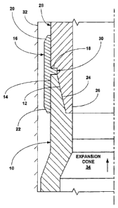
[0096] Referring to Fig. 1 a, a first tubular member 10 includes an internally
threaded
connection 12 at an end portion 14. As illustrated in Fig. 1 b, a first end of
a tubular sleeve 16
11
CA 02472284 2008-02-25
that includes an internal flange 18 and tapered portions, 20 and 22, at
opposite ends is then
mounted upon and receives the end portion 14 of the first tubular member 10.
In an
exemplary embodiment, the end portion 14 of the first tubular member 10 abuts
one side of
the internal flange 18 of the tubular sleeve 16, and the internal diameter of
the internal flange
of the tubular sleeve is substantially equal to or greater than the maximum
internal diameter
of the internally threaded connection 12 of the end portion of the first
tubular member. As
illustrated in Fig. 1 c, an externally threaded connection 24 of an end
portion 26 of a second
tubular member 28 having an annular recess 30 is then positioned within the
tubular sleeve
16 and threadably coupled to the internally threaded connection 12 of the end
portion 14 of
the first tubular member 10. In an exemplary embodiment, the internal flange
18 of the
tubular sleeve 16 mates with and is received within the annular recess 30 of
the end portion
26 of the second tubular member 28. Thus, the tubular sleeve 16 is coupled to
and
surrounds the external surfaces of the first and second tubular members, 10
and 28.
[0097] In an exemplary embodiment, the internally threaded connection 12 of
the end portion
14 of the first tubular member 10 is a box connection, and the externally
threaded connection
24 of the end portion 26 of the second tubular member 28 is a pin connection.
In an
exemplary embodiment, the internal diameter of the tubular sleeve 16 is at
least
approximately .020" greater than the outside diameters of the first and second
tubular
members, 10 and 28. In this manner, during the threaded coupling of the first
and second
tubular members, 10 and 28, fluidic materials within the first and second
tubular members
may be vented from the tubular members.
[0098] In an exemplary embodiment, as illustrated in Figs. 1d and le, the
first and second
tubular members, 10 and 28, and the tubular sleeve 16 may then be positioned
within
another structure 32 such as, for example, a wellbore, and radially expanded
and plastically
deformed, for example, by moving an expansion cone 34 through the interiors of
the first and
second tubular members. The tapered portions, 20 and 22, of the tubular sleeve
16 facilitate
the insertion and movement of the first and second tubular members within and
through the
structure 32, and the movement of the expansion cone 34 through the interiors
of the first
and second tubular members, 10 and 28, may be from top to bottom or from
bottom to top.
[0099] In an exemplary embodiment, during the radial expansion and plastic
deformation of
the first and second tubular members, 10 and 28, the tubular sleeve 16 is also
radially
expanded and plastically deformed. In an exemplary embodiment, as a result,
the tubular
sleeve 16 may be maintained in circumferential tension and the end portions,
14 and 26, of
the first and second tubular members, 10 and 28, may be maintained in
circumferential
compression.
[00100] In several exemplary embodiments, the first and second tubular
members, 10
and 28, are radially expanded and plastically deformed using the expansion
cone 32 in a
12
CA 02472284 2008-02-25
conventional manner and/or using one or more of the methods and apparatus
disclosed in
one or more of the following: U.S. Patent Nos. 6,497,289; 6,823,937;
6,328,113; 6,568,471;
6,575,240; 6,557,640; 6,604,763; 6,634,431; 6,745,845; and WO 01/04535.
13
CA 02472284 2008-02-25
[00101] In several alternative embodiments, the first and second tubular
members, 10
and 28, are radially expanded and plastically deformed using other
conventional methods for
radially expanding and plastically deforming tubular members such as, for
example, internal
pressurization and/or roller expansion devices. In an exemplary embodiment,
the roller
expansion devices are the commercially available roller expansion devices
available from
Weatherford International and/or as disclosed in U.S. 6,457,532 BI .
[00102] The use of the tubular sleeve 16 during (a) the coupling of the first
tubular
member 10 to the second tubular member 28, (b) the placement of the first and
second
tubular members in the structure 32, and (c) the radial expansion and plastic
deformation of
the first and second tubular members provides a number of significant
benefits. For
example, the tubular sleeve 16 protects the exterior surfaces of the end
portions, 14 and 26,
of the first and second tubular members, 10 and 28, during handling and
insertion of the
tubular members within the structure 32. In this manner, damage to the
exterior surfaces of
the end portions, 14 and 26, of the first and second tubular member, 10 and
28, are
prevented that could result in stress concentrations that could result in a
catastrophic failure
during subsequent radial expansion operations. Furthermore, the tubular sleeve
16
provides an alignment guide that facilitates the insertion and threaded
coupling of the second
tubular member 28 to the first tubular member 10. In this manner, misalignment
that could
result in damage to the threaded connections, 12 and 24, of the first and
second tubular
members, 10 and 28, may be avoided. In addition, during the relative rotation
of the second
tubular member with respect to the first tubular member, required during the
threaded
coupling of the first and second tubular members, the tubular sleeve 16
provides an
indication of to what degree the first and second tubular members are
threadably coupled.
For example, if the tubular sleeve 16 can be easily rotated, that would
indicate that the first
and second tubular members, 10 and 28, are not fully threadably coupled and in
intimate
contact with the internal flange 18 of the tubular sleeve. Furthermore, the
tubular sleeve 16
may prevent crack propagation during the radial expansion and plastic
deformation of the
first and second tubular members, 10 and 28. In this manner, failure modes
such as, for
example, longitudinal cracks in the end portions, 14 and 26, of the first and
second tubular
members may be limited in severity or eliminated all together. In addition,
after completing
the radial expansion and plastic deformation of the first and second tubular
members, 10 and
28, the tubular sleeve 16 may provide a fluid tight metal-to-metal seal
between interior
surface of the tubular sleeve and the exterior surfaces of the end portions,
14 and 26, of the
14
CA 02472284 2008-02-25
first and second tubular members. In this manner, fluidic materials are
prevented from
passing through the threaded connections, 12 and 24, of the first and second
tubular
members, 10 and 28, into the annulus between the first and second tubular
members and
the structure 32. Furthermore, because, following the radial expansion and
plastic
deformation of the first and second tubular members, 10 and 28, the tubular
sleeve 16 may
be maintained in circumferential tension and the end portions, 14 and 26, of
the first and
second tubular members, 10 and 28, may be maintained in circumferential
compression,
axial loads and/or torque loads may be transmitted through the tubular sleeve.
[00103] Referring to Figs. 2a and 2b, in an alternative embodiment, a tubular
sleeve
110 having an internal flange 112 and a tapered portion 114 is coupled to the
first and
second tubular members, 10 and 28. In particular, the tubular sleeve 110
receives and
mates with the end portion 14 of the first tubular member 10, and the internal
flange 112 of
the tubular sleeve is received within the annular recess 30 of the second
tubular member 28
proximate the end of the first tubular member. In this manner, the tubular
sleeve 110 is
coupled to the end portions, 14 and 26, of the first and second tubular
members, 10 and 28,
and the tubular sleeve covers the end portion 14 of the first tubular member
10.
[00104] In an exemplary embodiment, the first and second tubular members, 10
and
28, and the tubular sleeve 110 may then be positioned within the structure 32
and radially
expanded and plastically deformed, for example, by moving an expansion cone 34
through
the interiors of the first and second tubular members. In an exemplary
embodiment,
following the radial expansion and plastic deformation of the first and second
tubular
members, 10 and 28, the tubular sleeve 110 may be maintained in
circumferential tension
and the end portions, 14 and 26, of the first and second tubular members, 10
and 28, may be
maintained in circumferential compression.
[00105] The use of the tubular sleeve 110 during (a) the coupling of the first
tubular
member 10 to the second tubular member 28, (b) the placement of the first and
second
tubular members in the structure 32, and (c) the radial expansion and plastic
deformation of
the first and second tubular members provides a number of significant
benefits. For
example, the tubular sleeve 110 protects the exterior surface of the end
portion 14 of the first
tubular member 10 during handling and insertion of the tubular members within
the structure
32. In this manner, damage to the exterior surfaces of the end portion 14 of
the first tubular
member 10 is prevented that could result in stress concentrations that could
result in a
catastrophic failure during subsequent radial expansion operations. In
addition, during the
relative rotation of the second tubular member with respect to the first
tubular member,
required during the threaded coupling of the first and second tubular members,
the tubular
sleeve 110 provides an indication of to what degree the first and second
tubular members
are threadably coupled. For example, if the tubular sleeve 110 can be easily
rotated, that
CA 02472284 2008-02-25
would indicate that the first and second tubular members, 10 and 28, are not
fully threadably
coupled and in intimate contact with the internal flange 112 of the tubular
sleeve.
Furthermore, the tubular sleeve 110 may prevent crack propagation during the
radial
expansion and plastic deformation of the first and second tubular members, 10
and 28. In
this manner, failure modes such as, for example, longitudinal cracks in the
end portions, 14
and 26, of the first and second tubular members may be limited in severity or
eliminated all
together. In addition, after completing the radial expansion and plastic
deformation of the
first and second tubular members, 10 and 28, the tubular sleeve 110 may
provide a fluid tight
metal-to-metal seal between interior surface of the tubular sleeve and the
exterior surface of
the end portion14 of the first tubular member. In this manner, fluidic
materials are prevented
from passing through the threaded connections, 12 and 24, of the first and
second tubular
members, 10 and 28, into the annulus between the first and second tubular
members and
the structure 32. Furthermore, because, following the radial expansion and
plastic
deformation of the first and second tubular members, 10 and 28, the tubular
sleeve 110 may
be maintained in circumferential tension and the end portions, 14 and 26, of
the first and
second tubular members, 10 and 28, may be maintained in circumferential
compression,
axial loads and/or torque loads may be transmitted through the tubular sleeve.
[00106] Referring to Figs. 3a and 3b, in an alternative embodiment, a tubular
sleeve
210 having an internal flange 212, tapered portions, 214 and 216, at opposite
ends, and
annular sealing members, 218 and 220, positioned on opposite sides of the
internal flange,
is coupled to the first and second tubular members, 10 and 28. In particular,
the tubular
sleeve 210 receives and mates with the end portions, 14 and 26, of the first
and second
tubular members, 10 and 28, and the internal flange 212 of the tubular sleeve
is received
within the annular recess 30 of the second tubular member 28 proximate the end
of the first
tubular member. Furthermore, the sealing members, 218 and 220, of the tubular
sleeve 210
engage and fluidicly seal the interface between the tubular sleeve and the end
portions, 14
and 26, of the first and second tubular members, 10 and 28. In this manner,
the tubular
sleeve 210 is coupled to the end portions, 14 and 26, of the first and second
tubular
members, 10 and 28, and the tubular sleeve covers the end portions, 14 and 26,
of the first
and second tubular members, 10 and 28.
[00107] In an exemplary embodiment, the first and second tubular members, 10
and
28, and the tubular sleeve 210 may then be positioned within the structure 32
and radially
expanded and plastically deformed, for example, by moving an expansion cone 34
through
the interiors of the first and second tubular members. In an exemplary
embodiment,
following the radial expansion and plastic deformation of the first and second
tubular
members, 10 and 28, the tubular sleeve 210 may be maintained in
circumferential tension
and the end portions, 14 and 26, of the first and second tubular members, 10
and 28, may be
16
CA 02472284 2008-02-25
maintained in circumferential compression.
[00108] The use of the tubular sleeve 210 during (a) the coupling of the first
tubular
member 10 to the second tubular member 28, (b) the placement of the first and
second
tubular members in the structure 32, and (c) the radial expansion and plastic
deformation of
the first and second tubular members provides a number of significant
benefits. For
example, the tubular sleeve 210 protects the exterior surfaces of the end
portions, 14 and 26,
of the first and second tubular members, 10 and 28, during handling and
insertion of the
tubular members within the structure 32. In this manner, damage to the
exterior surfaces of
the end portions, 14 and 26, of the first and second tubular members, 10 and
28, is
prevented that could result in stress concentrations that could result in a
catastrophic failure
during subsequent radial expansion operations. In addition, during the
relative rotation of the
second tubular member with respect to the first tubular member, required
during the threaded
coupling of the first and second tubular members, the tubular sleeve 210
provides an
indication of to what degree the first and second tubular members are
threadably coupled.
For example, if the tubular sleeve 210 can be easily rotated, that would
indicate that the first
and second tubular members, 10 and 28, are not fully threadably coupled and in
intimate
contact with the internal flange 212 of the tubular sleeve. Furthermore, the
tubular sleeve
210 may prevent crack propagation during the radial expansion and plastic
deformation of
the first and second tubular members, 10 and 28. In this manner, failure modes
such as, for
example, longitudinal cracks in the end portions, 14 and 26, of the first and
second tubular
members, 10 and 28, may be limited in severity or eliminated all together. In
addition, after
completing the radial expansion and plastic deformation of the first and
second tubular
members, 10 and 28, the tubular sleeve 210 may provide a fluid tight metal-to-
metal seal
between interior surface of the tubular sleeve and the exterior surfaces of
the end portions,14
and 26, of the first and second tubular members. In this manner, fluidic
materials are
prevented from passing through the threaded connections, 12 and 24, of the
first and second
tubular members, 10 and 28, into the annulus between the first and second
tubular members
and the structure 32. Furthermore, because, following the radial expansion and
plastic
deformation of the first and second tubular members, 10 and 28, the tubular
sleeve 210 may
be maintained in circumferential tension and the end portions, 14 and 26, of
the first and
second tubular members, 10 and 28, may be maintained in circumferential
compression,
axial loads and/or torque loads may be transmitted through the tubular sleeve.
[00109] Referring to Figs. 4a and 4b, in an alternative embodiment, a tubular
sleeve
310 having an internal flange 312, tapered portions, 314 and 316, at opposite
ends, and an
annular sealing member 318 positioned on the exterior surface of the tubular
sleeve, is
coupled to the first and second tubular members, 10 and 28. In particular, the
tubular sleeve
310 receives and mates with the end portions, 14 and 26, of the first and
second tubular
17
CA 02472284 2008-02-25
members, 10 and 28, and the internal flange 312 of the tubular sleeve is
received within the
annular recess 30 of the second tubular member 28 proximate the end of the
first tubular
member. In this manner, the tubular sleeve 310 is coupled to the end portions,
14 and 26, of
the first and second tubular members, 10 and 28, and the tubular sleeve covers
the end
portions, 14 and 26, of the first and second tubular members, 10 and 28.
[00110] In an exemplary embodiment, the first and second tubular members, 10
and
28, and the tubular sleeve 310 may then be positioned within the structure 32
and radially
expanded and plastically deformed, for example, by moving an expansion cone 34
through
the interiors of the first and second tubular members. In an exemplary
embodiment,
following the radial expansion and plastic deformation of the first and second
tubular
members, 10 and 28, the tubular sleeve 310 may be maintained in
circumferential tension
and the end portions, 14 and 26, of the first and second tubular members, 10
and 28, may be
maintained in circumferential compression. Furthermore, in an exemplary
embodiment,
following the radial expansion and plastic deformation of the first and second
tubular
members, 10 and 28, the annular sealing member 318 circumferentially engages
the interior
surface of the structure 32 thereby preventing the passage of fluidic
materials through the
annulus between the tubular sleeve 310 and the structure. In this manner, the
tubular sleeve
310 may provide an expandable packer element.
[00111] The use of the tubular sleeve 310 during (a) the coupling of the first
tubular
member 10 to the second tubular member 28, (b) the placement of the first and
second
tubular members in the structure 32, and (c) the radial expansion and plastic
deformation of
the first and second tubular members provides a number of significant
benefits. For
example, the tubular sleeve 310 protects the exterior surfaces of the end
portions, 14 and 26,
of the first and second tubular members, 10 and 28, during handling and
insertion of the
tubular members within the structure 32. In this manner, damage to the
exterior surfaces of
the end portions, 14 and 26, of the first and second tubular members, 10 and
28, is
prevented that could result in stress concentrations that could result in a
catastrophic failure
during subsequent radial expansion operations. In addition, during the
relative rotation of the
second tubular member with respect to the first tubular member, required
during the threaded
coupling of the first and second tubular members, the tubular sleeve 310
provides an
indication of to what degree the first and second tubular members are
threadably coupled.
For example, if the tubular sleeve 310 can be easily rotated, that would
indicate that the first
and second tubular members, 10 and 28, are not fully threadably coupled and in
intimate
contact with the internal flange 312 of the tubular sleeve. Furthermore, the
tubular sleeve
310 may prevent crack propagation during the radial expansion and plastic
deformation of
the first and second tubular members, 10 and 28. In this manner, failure modes
such as, for
example, longitudinal cracks in the end portions, 14 and 26, of the first and
second tubular
18
CA 02472284 2008-02-25
members, 10 and 28, may be limited in severity or eliminated all together. In
addition, after
completing the radial expansion and plastic deformation of the first and
second tubular
members, 10 and 28, the tubular sleeve 310 may provide a fluid tight metal-to-
metal seal
between interior surface of the tubular sleeve and the exterior surfaces of
the end portions,14
and 26, of the first and second tubular members. In this manner, fluidic
materials are
prevented from passing through the threaded connections, 12 and 24, of the
first and second
tubular members, 10 and 28, into the annulus between the first and second
tubular members
and the structure 32. Furthermore, because, following the radial expansion and
plastic
deformation of the first and second tubular members, 10 and 28, the tubular
sleeve 310 may
be maintained in circumferential tension and the end portions, 14 and 26, of
the first and
second tubular members, 10 and 28, may be maintained in circumferential
compression,
axial loads and/or torque loads may be transmitted through the tubular sleeve.
In addition,
because, following the radial expansion and plastic deformation of the first
and second
tubular members, 10 and 28, the annular sealing member 318 may
circumferentially engage
the interior surface of the structure 32, the tubular sleeve 310 may provide
an expandable
packer element.
[00112] Referring to Figs. 5a and 5b, in an alternative embodiment, a non-
metallic
tubular sleeve 410 having an internal flange 412, and tapered portions, 414
and 416, at
opposite ends, is coupled to the first and second tubular members, 10 and 28.
In particular,
the tubular sleeve 410 receives and mates with the end portions, 14 and 26, of
the first and
second tubular members, 10 and 28, and the internal flange 412 of the tubular
sleeve is
received within the annular recess 30 of the second tubular member 28
proximate the end of
the first tubular member. In this manner, the tubular sleeve 410 is coupled to
the end
portions, 14 and 26, of the first and second tubular members, 10 and 28, and
the tubular
sleeve covers the end portions, 14 and 26, of the first and second tubular
members, 10 and
28.
[00113] In several exemplary embodiments, the tubular sleeve 410 may be
plastic,
ceramic, elastomeric, composite and/or a frangible material.
[00114] In an exemplary embodiment, the first and second tubular members, 10
and
28, and the tubular sleeve 410 may then be positioned within the structure 32
and radially
expanded and plastically deformed, for example, by moving an expansion cone 34
through
the interiors of the first and second tubular members. In an exemplary
embodiment,
following the radial expansion and plastic deformation of the first and second
tubular
members, 10 and 28, the tubular sleeve 410 may be maintained in
circumferential tension
and the end portions, 14 and 26, of the first and second tubular members, 10
and 28, may be
maintained in circumferential compression. Furthermore, in an exemplary
embodiment,
during the radial expansion and plastic deformation of the first and second
tubular members,
19
CA 02472284 2008-02-25
and 28, the tubular sleeve 310 may be broken off of the first and second
tubular
members.
[00115] The use of the tubular sleeve 410 during (a) the coupling of the first
tubular
member 10 to the second tubular member 28, (b) the placement of the first and
second
tubular members in the structure 32, and (c) the radial expansion and plastic
deformation of
the first and second tubular members provides a number of significant
benefits. For
example, the tubular sleeve 410 protects the exterior surfaces of the end
portions, 14 and 26,
of the first and second tubular members, 10 and 28, during handling and
insertion of the
tubular members within the structure 32. In this manner, damage to the
exterior surfaces of
the end portions, 14 and 26, of the first and second tubular members, 10 and
28, is
prevented that could result in stress concentrations that could result in a
catastrophic failure
during subsequent radial expansion operations. In addition, during the
relative rotation of the
second tubular member with respect to the first tubular member, required
during the threaded
coupling of the first and second tubular members, the tubular sleeve 410
provides an
indication of to what degree the first and second tubular members are
threadably coupled.
For example, if the tubular sleeve 410 can be easily rotated, that would
indicate that the first
and second tubular members, 10 and 28, are not fully threadably coupled and in
intimate
contact with the internal flange 412 of the tubular sleeve. Furthermore, the
tubular sleeve
410 may prevent crack propagation during the radial expansion and plastic
deformation of
the first and second tubular members, 10 and 28. In this manner, failure modes
such as, for
example, longitudinal cracks in the end portions, 14 and 26, of the first and
second tubular
members, 10 and 28, may be limited in severity or eliminated all together. In
addition, after
completing the radial expansion and plastic deformation of the first and
second tubular
members, 10 and 28, the tubular sleeve 410 may provide a fluid tight metal-to-
metal seal
between interior surface of the tubular sleeve and the exterior surfaces of
the end portions,14
and 26, of the first and second tubular members. In this manner, fluidic
materials are
prevented from passing through the threaded connections, 12 and 24, of the
first and second
tubular members, 10 and 28, into the annulus between the first and second
tubular members
and the structure 32. Furthermore, because, following the radial expansion and
plastic
deformation of the first and second tubular members, 10 and 28, the tubular
sleeve 410 may
be maintained in circumferential tension and the end portions, 14 and 26, of
the first and
second tubular members, 10 and 28, may be maintained in circumferential
compression,
axial loads and/or torque loads may be transmitted through the tubular sleeve.
In addition,
because, during the radial expansion and plastic deformation of the first and
second tubular
members, 10 and 28, the tubular sleeve 410 may be broken off of the first and
second
tubular members, the final outside diameter of the first and second tubular
members may
more closely match the inside diameter of the structure 32.
CA 02472284 2008-02-25
[00116] Referring to Fig. 6a, in an exemplary embodiment, a tubular sleeve 510
includes an internal flange 512, tapered portions, 514 and 516, at opposite
ends, and defines
one or more axial slots 518. In an exemplary embodiment, during the radial
expansion and
plastic deformation of the first and second tubular members, 10 and 28, the
axial slots 518
reduce the required radial expansion forces.
[00117] Referring to Fig. 6b, in an exemplary embodiment, a tubular sleeve 610
includes an internal flange 612, tapered portions, 614 and 616, at opposite
ends, and defines
one or more offset axial slots 618. In an exemplary embodiment, during the
radial expansion
and plastic deformation of the first and second tubular members, 10 and 28,
the axial slots
618 reduce the required radial expansion forces.
[00118] Referring to Fig. 6c, in an exemplary embodiment, a tubular sleeve 710
includes an internal flange 712, tapered portions, 714 and 716, at opposite
ends, and defines
one or more radial openings 718. In an exemplary embodiment, during the radial
expansion
and plastic deformation of the first and second tubular members, 10 and 28,
the radial
openings 718 reduce the required radial expansion forces.
[00119] Referring to Fig. 6d, in an exemplary embodiment, a tubular sleeve 810
includes an internal flange 812, tapered portions, 814 and 816, at opposite
ends, and defines
one or more axial slots 818 that extend from the ends of the tubular sleeve.
In an exemplary
embodiment, during the radial expansion and plastic deformation of the first
and second
tubular members, 10 and 28, the axial slots 818 reduce the required radial
expansion forces.
[00120] Referring to Fig. 7a, a first tubular member 910 includes an
internally threaded
connection 912 at an end portion 914 and a recessed portion 916 having a
reduced outside
diameter. As illustrated in Fig. 7b, a first end of a tubular sleeve 918 that
includes annular
sealing members, 920 and 922, at opposite ends, tapered portions, 924 and 926,
at one end,
and tapered portions, 928 and 930, at another end is then mounted upon and
receives the
end portion 914 of the first tubular member 910. In an exemplary embodiment, a
resilient
retaining ring 930 is positioned between the lower end of the tubular sleeve
918 and the
recessed portion 916 of the first tubular member 910 in order to couple the
tubular sleeve to
the first tubular member. In an exemplary embodiment, the resilient retaining
ring 930 is a
split ring having a toothed surface in order to lock the tubular sleeve 918 in
place.
[00121] As illustrated in Fig. 7c, an externally threaded connection 934 of an
end
portion 936 of a second tubular member 938 having a recessed portion 940
having a
reduced outside diameter is then positioned within the tubular sleeve 918 and
threadably
coupled to the internally threaded connection 912 of the end portion 914 of
the first tubular
member 910. In an exemplary embodiment, a resilient retaining ring 942 is
positioned
between the upper end of the tubular sleeve 918 and the recessed portion 940
of the second
tubular member 938 in order to couple the tubular sleeve to the second tubular
member. In
21
CA 02472284 2008-02-25
an exemplary embodiment, the resilient retaining ring 942 is a split ring
having a toothed
surface in order to lock the tubular sleeve 918 in place.
[00122] In an exemplary embodiment, the internally threaded connection 912 of
the
end portion 914 of the first tubular member 910 is a box connection, and the
externally
threaded connection 934 of the end portion 936 of the second tubular member
938 is a pin
connection. In an exemplary embodiment, the internal diameter of the tubular
sleeve 918 is
at least approximately .020" greater than the outside diameters of the end
portions, 914 and
936, of the first and second tubular members, 910 and 938. In this manner,
during the
threaded coupling of the first and second tubular members, 910 and 938,
fluidic materials
within the first and second tubular members may be vented from the tubular
members.
[0019] In an exemplary embodiment, as illustrated in Figs. 7d and 7e, the
first and second
tubular members, 910 and 938, and the tubular sleeve 918 may then be
positioned within
another structure 32 such as, for example, a wellbore, and radially expanded
and plastically
deformed, for example, by moving an expansion cone 34 through the interiors of
the first and
second tubular members. The tapered portions, 924 and 928, of the tubular
sleeve 918
facilitate the insertion and movement of the first and second tubular members
within and
through the structure 32, and the movement of the expansion cone 34 through
the interiors of
the first and second tubular members, 910 and 938, may be from top to bottom
or from
bottom to top.
[00123] In an exemplary embodiment, during the radial expansion and plastic
deformation of the first and second tubular members, 910 and 938, the tubular
sleeve 918 is
also radially expanded and plastically deformed. In an exemplary embodiment,
as a result,
the tubular sleeve 918 may be maintained in circumferential tension and the
end portions,
914 and 936, of the first and second tubular members, 910 and 938, may be
maintained in
circumferential compression.
[00124] The use of the tubular sleeve 918 during (a) the coupling of the first
tubular
member 910 to the second tubular member 938, (b) the placement of the first
and second
tubular members in the structure 32, and (c) the radial expansion and plastic
deformation of
the first and second tubular members provides a number of significant
benefits. For
example, the tubular sleeve 918 protects the exterior surfaces of the end
portions, 914 and
936, of the first and second tubular members, 910 and 938, during handling and
insertion of
the tubular members within the structure 32. In this manner, damage to the
exterior surfaces
of the end portions, 914 and 936, of the first and second tubular member, 910
and 938, are
prevented that could result in stress concentrations that could result in a
catastrophic failure
during subsequent radial expansion operations. Furthermore, the tubular sleeve
918
provides an alignment guide that facilitates the insertion and threaded
coupling of the second
tubular member 938 to the first tubular member 910. In this manner,
misalignment that could
22
CA 02472284 2008-02-25
result in damage to the threaded connections, 912 and 934, of the first and
second tubular
members, 910 and 938, may be avoided. Furthermore, the tubular sleeve 918 may
prevent
crack propagation during the radial expansion and plastic deformation of the
first and second
tubular members, 910 and 938. In this manner, failure modes such as, for
example,
longitudinal cracks in the end portions, 914 and 936, of the first and second
tubular members
may be limited in severity or eliminated all together. In addition, after
completing the radial
expansion and plastic deformation of the first and second tubular members, 910
and 938, the
tubular sleeve 918 may provide a fluid tight metal-to-metal seal between
interior surface of
the tubular sleeve and the exterior surfaces of the end portions, 914 and 936,
of the first and
second tubular members. In this manner, fluidic materials are prevented from
passing
through the threaded connections, 912 and 934, of the first and second tubular
members,
910 and 938, into the annulus between the first and second tubular members and
the
structure 32. Furthermore, because, following the radial expansion and plastic
deformation
of the first and second tubular members, 910 and 938, the tubular sleeve 918
may be
maintained in circumferential tension and the end portions, 914 and 936, of
the first and
second tubular members, 910 and 938, may be maintained in circumferential
compression,
axial loads and/or torque loads may be transmitted through the tubular sleeve.
In addition,
the annular sealing members, 920 and 922, of the tubular sleeve 918 may
provide a fluid
tight seal between the tubular sleeve and the end portions, 914 and 936, of
the first and
second tubular members, 910 and 938.
[00125] Referring to Fig. 8a, a first tubular member 1010 includes an
internally
threaded connection 1012 at an end portion 1014 and a recessed portion 1016
having a
reduced outside diameter. As illustrated in Fig. 8b, a first end of a tubular
sleeve 1018 that
includes annular sealing members, 1020 and 1022, at opposite ends, tapered
portions, 1024
and 1026, at one end, and tapered portions, 1028 and 1030, at another end is
then mounted
upon and receives the end portion 1014 of the first tubular member 1010. In an
exemplary
embodiment, as illustrated in Fig. 8c, the end of the tubular sleeve 1018 is
then crimped onto
the recessed portion 1016 of the first tubular member 1010 in order to couple
the tubular
sleeve to the first tubular member.
[00126] As illustrated in Fig. 8d, an externally threaded connection 1032 of
an end
portion 1034 of a second tubular member 1036 having a recessed portion 1038
having a
reduced external diameter is then positioned within the tubular sleeve 1018
and threadably
coupled to the internally threaded connection 1012 of the end portion 1014 of
the first tubular
member 1010. In an exemplary embodiment, as illustrated in Fig. 8e, the other
end of the
tubular sleeve 1018 is then crimped into the recessed portion 1038 of the
second tubular
member 1036 in order to couple the tubular sleeve to the second tubular
member.
[00127] In an exemplary embodiment, the internally threaded connection 1012 of
the
23
CA 02472284 2008-02-25
end portion 1014 of the first tubular member 1010 is a box connection, and the
externally
threaded connection 1032 of the end portion 1034 of the second tubular member
1036 is a
pin connection. In an exemplary embodiment, the internal diameter of the
tubular sleeve
1018 is at least approximately .020" greater than the outside diameters of the
end portions,
1014 and 1034, of the first and second tubular members, 1010 and 1036. In this
manner,
during the threaded coupling of the first and second tubular members, 1010 and
1036, fluidic
materials within the first and second tubular members may be vented from the
tubular
members.
[00128] In an exemplary embodiment, as illustrated in Figs. 8f and 8g, the
first and
second tubular members, 1010 and 1036, and the tubular sleeve 1018 may then be
positioned within another structure 32 such as, for example, a wellbore, and
radially
expanded and plastically deformed, for example, by moving an expansion cone 34
through
the interiors of the first and second tubular members. The movement of the
expansion cone
34 through the interiors of the first and second tubular members, 1010 and
1036, may be
from top to bottom or from bottom to top.
[00129] In an exemplary embodiment, during the radial expansion and plastic
deformation of the first and second tubular members, 1010 and 1036, the
tubular sleeve
1018 is also radially expanded and plastically deformed. In an exemplary
embodiment, as a
result, the tubular sleeve 1018 may be maintained in circumferential tension
and the end
portions, 1014 and 1034, of the first and second tubular members, 1010 and
1036, may be
maintained in circumferential compression.
[00130] The use of the tubular sleeve 1018 during (a) the coupling of the
first tubular
member 1010 to the second tubular member 1036, (b) the placement of the first
and second
tubular members in the structure 32, and (c) the radial expansion and plastic
deformation of
the first and second tubular members provides a number of significant
benefits. For
example, the tubular sleeve 1018 protects the exterior surfaces of the end
portions, 1014 and
1034, of the first and second tubular members, 1010 and 1036, during handling
and insertion
of the tubular members within the structure 32. In this manner, damage to the
exterior
surfaces of the end portions, 1014 and 1034, of the first and second tubular
members, 1010
and 1036, are prevented that could result in stress concentrations that could
result in a
catastrophic failure during subsequent radial expansion operations.
Furthermore, the tubular
sleeve 1018 provides an alignment guide that facilitates the insertion and
threaded coupling
of the second tubular member 1036 to the first tubular member 1010. In this
manner,
misalignment that could result in damage to the threaded connections, 1012 and
1032, of the
first and second tubular members, 1010 and 1036, may be avoided. Furthermore,
the
tubular sleeve 1018 may prevent crack propagation during the radial expansion
and plastic
deformation of the first and second tubular members, 1010 and 1036. In this
manner, failure
24
CA 02472284 2008-02-25
modes such as, for example, longitudinal cracks in the end portions, 1014 and
1034, of the
first and second tubular members may be limited in severity or eliminated all
together. In
addition, after completing the radial expansion and plastic deformation of the
first and second
tubular members, 1010 and 1036, the tubular sleeve 1018 may provide a fluid
tight metal-to-
metal seal between interior surface of the tubular sleeve and the exterior
surfaces of the end
portions, 1014 and 1034, of the first and second tubular members. In this
manner, fluidic
materials are prevented from passing through the threaded connections, 1012
and 1032, of
the first and second tubular members, 1010 and 1036, into the annulus between
the first and
second tubular members and the structure 32. Furthermore, because, following
the radial
expansion and plastic deformation of the first and second tubular members,
1010 and 1036,
the tubular sleeve 1018 may be maintained in circumferential tension and the
end portions,
1014 and 1034, of the first and second tubular members, 1010 and 1036, may be
maintained
in circumferential compression, axial loads and/or torque loads may be
transmitted through
the tubular sleeve. In addition, the annular sealing members, 1020 and 1022,
of the tubular
sleeve 1018 may provide a fluid tight seal between the tubular sleeve and the
end portions,
1014 and 1034, of the first and second tubular members, 1010 and 1036.
[00131] Referring to Fig. 9a, a first tubular member 1110 includes an
internally
threaded connection 1112 at an end portion 1114. As illustrated in Fig. 9b, a
first end of a
tubular sleeve 1116 having tapered portions, 1118 and 1120, at opposite ends,
is then
mounted upon and receives the end portion 1114 of the first tubular member
1110. In an
exemplary embodiment, a toothed resilient retaining ring 1122 is then attached
to first tubular
member 1010 below the end of the tubular sleeve 1116 in order to couple the
tubular sleeve
to the first tubular member.
[00132] As illustrated in Fig. 9c, an externally threaded connection 1124 of
an end
portion 1126 of a second tubular member 1128 is then positioned within the
tubular sleeve
1116 and threadably coupled to the internally threaded connection 1112 of the
end portion
1114 of the first tubular member 1110. In an exemplary embodiment, a toothed
resilient
retaining ring 1130 is then attached to second tubular member 1128 above the
end of the
tubular sleeve 1116 in order to couple the tubular sleeve to the second
tubular member.
[00133] In an exemplary embodiment, the internally threaded connection 1112 of
the
end portion 1114 of the first tubular member 1110 is a box connection, and the
externally
threaded connection 1124 of the end portion 1126 of the second tubular member
1128 is a
pin connection. In an exemplary embodiment, the internal diameter of the
tubular sleeve
1116 is at least approximately .020" greater than the outside diameters of the
end portions,
1114 and 1126, of the first and second tubular members, 1110 and 1128. In this
manner,
during the threaded coupling of the first and second tubular members, 1110 and
1128, fluidic
materials within the first and second tubular members may be vented from the
tubular
CA 02472284 2008-02-25
members.
[00134] In an exemplary embodiment, as illustrated in Figs. 9d and 9e, the
first and
second tubular members, 1110 and 1128, and the tubular sleeve 1116 may then be
positioned within another structure 32 such as, for example, a welibore, and
radially
expanded and plastically deformed, for example, by moving an expansion cone 34
through
the interiors of the first and second tubular members. The movement of the
expansion cone
34 through the interiors of the first and second tubular members, 1110 and
1128, may be
from top to bottom or from bottom to top.
[00135] In an exemplary embodiment, during the radial expansion and plastic
deformation of the first and second tubular members, 1110 and 1128, the
tubular sleeve
1116 is also radially expanded and plastically deformed. In an exemplary
embodiment, as a
result, the tubular sleeve 1116 may be maintained in circumferential tension
and the end
portions, 1114 and 1126, of the first and second tubular members, 1110 and
1128, may be
maintained in circumferential compression.
[00136] The use of the tubular sleeve 1116 during (a) the coupling of the
first tubular
member 1110 to the second tubular member 1128, (b) the placement of the first
and second
tubular members in the structure 32, and (c) the radial expansion and plastic
deformation of
the first and second tubular members provides a number of significant
benefits. For
example, the tubular sleeve 1116 protects the exterior surfaces of the end
portions, 1114 and
1126, of the first and second tubular members, 1110 and 1128, during handling
and insertion
of the tubular members within the structure 32. In this manner, damage to the
exterior
surfaces of the end portions, 1114 and 1126, of the first and second tubular
members, 1110
and 1128, are prevented that could result in stress concentrations that could
result in a
catastrophic failure during subsequent radial expansion operations.
Furthermore, the tubular
sleeve 1116 provides an alignment guide that facilitates the insertion and
threaded coupling
of the second tubular member 1128 to the first tubular member 1110. In this
manner,
misalignment that could result in damage to the threaded connections, 1112 and
1124, of the
first and second tubular members, 1110 and 1128, may be avoided. Furthermore,
the
tubular sleeve 1116 may prevent crack propagation during the radial expansion
and plastic
deformation of the first and second tubular members, 1110 and 1128. In this
manner, failure
modes such as, for example, longitudinal cracks in the end portions, 1114 and
1126, of the
first and second tubular members may be limited in severity or eliminated all
together. In,
addition, after completing the radial expansion and plastic deformation of the
first and second
tubular members, 1110 and 1128, the tubular sleeve 1116 may provide a fluid
tight metal-to-
metal seal between interior surface of the tubular sleeve and the exterior
surfaces of the end
portions, 1114 and 1128, of the first and second tubular members. In this
manner, fluidic
materials are prevented from passing through the threaded connections, 1112
and 1124, of
26
CA 02472284 2008-02-25
the first and second tubular members, 1110 and 1128, into the annulus between
the first and
second tubular members and the structure 32. Furthermore, because, following
the radial
expansion and plastic deformation of the first and second tubular members,
1110 and 1128,
the tubular sleeve 1116 may be maintained in circumferential tension and the
end portions,
1114 and 1126, of the first and second tubular members, 1110 and 1128, may be
maintained
in circumferential compression, axial loads and/or torque loads may be
transmitted through
the tubular sleeve.
[00137] Referring to Fig. 10a, a first tubular member 1210 includes an
internally
threaded connection 1212 at an end portion 1214. As illustrated in Fig. 10b, a
first end of a
tubular sleeve 1216 having tapered portions, 1218 and 1220, at one end and
tapered
portions, 1222 and 1224, at another end, is then mounted upon and receives the
end portion
1114 of the first tubular member 1110. In an exemplary embodiment, a resilient
elastomeric
O-ring 1226 is then positioned on the first tubular member 1210 below the
tapered portion
1224 of the tubular sleeve 1216 in order to couple the tubular sleeve to the
first tubular
member.
[00138] As illustrated in Fig. 1 Oc, an externally threaded connection 1228 of
an end
portion 1230 of a second tubular member 1232 is then positioned within the
tubular sleeve
1216 and threadably coupled to the internally threaded connection 1212 of the
end portion
1214 of the first tubular member 1210. In an exemplary embodiment, a resilient
elastomeric
O-ring 1234 is then positioned on the second tubular member 1232 below the
tapered
portion 1220 of the tubular sleeve 1216 in order to couple the tubular sleeve
to the first
tubular member.
[00139] In an exemplary embodiment, the internally threaded connection 1212 of
the
end portion 1214 of the first tubular member 1210 is a box connection, and the
externally
threaded connection 1228 of the end portion 1230 of the second tubular member
1232 is a
pin connection. In an exemplary embodiment, the internal diameter of the
tubular sleeve
1216 is at least approximately .020" greater than the outside diameters of the
end portions,
1214 and 1230, of the first and second tubular members, 1210 and 1232. In this
manner,
during the threaded coupling of the first and second tubular members, 1210 and
1232, fluidic
materials within the first and second tubular members may be vented from the
tubular
members.
[00140] In an exemplary embodiment, as illustrated in Figs. 10d and 10e, the
first and
second tubular members, 1210 and 1232, and the tubular sleeve 1216 may then be
positioned within another structure 32 such as, for example, a wellbore, and
radially
expanded and plastically deformed, for example, by moving an expansion cone 34
through
the interiors of the first and second tubular members. The movement of the
expansion cone
34 through the interiors of the first and second tubular members, 1210 and
1232, may be
27
CA 02472284 2008-02-25
from top to bottom or from bottom to top.
[00141] In an exemplary embodiment, during the radial expansion and plastic
deformation of the first and second tubular members, 1210 and 1232, the
tubular sleeve
1216 is also radially expanded and plastically deformed. In an exemplary
embodiment, as a
result, the tubular sleeve 1216 may be maintained in circumferential tension
and the end
portions, 1214 and 1230, of the first and second tubular members, 1210 and
1232, may be
maintained in circumferential compression.
[00142] The use of the tubular sleeve 1216 during (a) the coupling of the
first tubular
member 1210 to the second tubular member 1232, (b) the placement of the first
and second
tubular members in the structure 32, and (c) the radial expansion and plastic
deformation of
the first and second tubular members provides a number of significant
benefits. For
example, the tubular sleeve 1216 protects the exterior surfaces of the end
portions, 1214 and
1230, of the first and second tubular members, 1210 and 1232, during handling
and insertion
of the tubular members within the structure 32. In this manner, damage to the
exterior
surfaces of the end portions, 1214 and 1230, of the first and second tubular
members, 1210
and 1232, are prevented that could result in stress concentrations that could
result in a
catastrophic failure during subsequent radial expansion operations.
Furthermore, the tubular
sleeve 1216 provides an alignment guide that facilitates the insertion and
threaded coupling
of the second tubular member 1232 to the first tubular member 1210. In this
manner,
misalignment that could result in damage to the threaded connections, 1212 and
1228, of the
first and second tubular members, 1210 and 1232, may be avoided. Furthermore,
the
tubular sleeve 1216 may prevent crack propagation during the radial expansion
and plastic
deformation of the first and second tubular members, 1210 and 1232. In this
manner, failure
modes such as, for example, longitudinal cracks in the end portions, 1214 and
1230, of the
first and second tubular members may be limited in severity or eliminated all
together. In
addition, after completing the radial expansion and plastic deformation of the
first and second
tubular members, 1210 and 1232, the tubular sleeve 1216 may provide a fluid
tight metal-to-
metal seal between interior surface of the tubular sleeve and the exterior
surfaces of the end
portions, 1214 and 1230, of the first and second tubular members. In this
manner, fluidic
materials are prevented from passing through the threaded connections, 1212
and 1228, of
the first and second tubular members, 1210 and 1232, into the annulus between
the first and
second tubular members and the structure 32. Furthermore, because, following
the radial
expansion and plastic deformation of the first and second tubular members,
1210 and 1232,
the tubular sleeve 1216 may be maintained in circumferential tension and the
end portions,
1214 and 1230, of the first and second tubular members, 1210 and 1232, may be
maintained
in circumferential compression, axial loads and/or torque loads may be
transmitted through
the tubular sleeve.
28
CA 02472284 2008-02-25
[00143] Referring to Fig. 11a, a first tubular member 1310 includes an
internally
threaded connection 1312 at an end portion 1314. As illustrated in Fig. 11 b,
a first end of a
tubular sleeve 1316 having tapered portions, 1318 and 1320, at opposite ends
is then
mounted upon and receives the end portion 1314 of the first tubular member
1310. In an
exemplary embodiment, an annular resilient retaining member 1322 is then
positioned on the
first tubular member 1310 below the bottom end of the tubular sleeve 1316 in
order to couple
the tubular sleeve to the first tubular member.
[00144] As illustrated in Fig. 11 c, an externally threaded connection 1324 of
an end
portion 1326 of a second tubular member 1328 is then positioned within the
tubular sleeve
1316 and threadably coupled to the internally threaded connection 1312 of the
end portion
1314 of the first tubular member 1310. In an exemplary embodiment, an annular
resilient
retaining member 1330 is then positioned on the second tubular member 1328
above the top
end of the tubular sleeve 1316 in order to couple the tubular sleeve to the
second tubular
member.
[00145] In an exemplary embodiment, the internally threaded connection 1312 of
the
end portion 1314 of the first tubular member 1310 is a box connection, and the
externally
threaded connection 1324 of the end portion 1326 of the second tubular member
1328 is a
pin connection. In an exemplary embodiment, the internal diameter of the
tubular sleeve
1316 is at least approximately .020" greater than the outside diameters of the
end portions,
1314 and 1326, of the first and second tubular members, 1310 and 1328. In this
manner,
during the threaded coupling of the first and second tubular members, 1310 and
1328, fluidic
materials within the first and second tubular members may be vented from the
tubular
members.
[00146] In an exemplary embodiment, as illustrated in Figs. 11 d and 11 e, the
first and
second tubular members, 1310 and 1328, and the tubular sleeve 1316 may then be
positioned within another structure 32 such as, for example, a wellbore, and
radially
expanded and plastically deformed, for example, by moving an expansion cone 34
through
the interiors of the first and second tubular members. The movement of the
expansion cone
34 through the interiors of the first and second tubular members, 1310 and
1328, may be
from top to bottom or from bottom to top.
[00147] In an exemplary embodiment, during the radial expansion and plastic
deformation of the first and second tubular members, 1310 and 1328, the
tubular sleeve
1316 is also radially expanded and plastically deformed. In an exemplary
embodiment, as a
result, the tubular sleeve 1316 may be maintained in circumferential tension
and the end
portions, 1314 and 1326, of the first and second tubular members, 1310 and
1328, may be
maintained in circumferential compression.
[00148] The use of the tubular sleeve 1316 during (a) the coupling of the
first tubular
29
CA 02472284 2008-02-25
member 1310 to the second tubular member 1328, (b) the placement of the first
and second
tubular members in the structure 32, and (c) the radial expansion and plastic
deformation of
the first and second tubular members provides a number of significant
benefits. For
example, the tubular sleeve 1316 protects the exterior surfaces of the end
portions, 1314 and
1326, of the first and second tubular members, 1310 and 1328, during handling
and insertion
of the tubular members within the structure 32. In this manner, damage to the
exterior
surfaces of the end portions, 1314 and 1326, of the first and second tubular
members, 1310
and 1328, are prevented that could result in stress concentrations that could
result in a
catastrophic failure during subsequent radial expansion operations.
Furthermore, the tubular
sleeve 1316 provides an alignment guide that facilitates the insertion and
threaded coupling
of the second tubular member 1328 to the first tubular member 1310. In this
manner,
misalignment that could result in damage to the threaded connections, 1312 and
1324, of the
first and second tubular members, 1310 and 1328, may be avoided. Furthermore,
the
tubular sleeve 1316 may prevent crack propagation during the radial expansion
and plastic
deformation of the first and second tubular members, 1310 and 1328. In this
manner, failure
modes such as, for example, longitudinal cracks in the end portions, 1314 and
1326, of the
first and second tubular members may be limited in severity or eliminated all
together. In
addition, after completing the radial expansion and plastic deformation of the
first and second
tubular members, 1310 and 1328, the tubular sleeve 1316 may provide a fluid
tight metal-to-
metal seal between interior surface of the tubular sleeve and the exterior
surfaces of the end
portions, 1314 and 1326, of the first and second tubular members. In this
manner, fluidic
materials are prevented from passing through the threaded connections, 1312
and 1324, of
the first and second tubular members, 1310 and 1328, into the annulus between
the first and
second tubular members and the structure 32. Furthermore, because, following
the radial
expansion and plastic deformation of the first and second tubular members,
1310 and 1328,
the tubular sleeve 1316 may be maintained in circumferential tension and the
end portions,
1314 and 1326, of the first and second tubular members, 1310 and 1328, may be
maintained
in circumferential compression, axial loads and/or torque loads may be
transmitted through
the tubular sleeve.
[00149] Referring to Fig. 12a, a first tubular member 1410 includes an
internally
threaded connection 1412 and an annular recess 1414 at an end portion 1416. As
illustrated
in Fig. 12b, a first end of a tubular sleeve 1418 that includes an external
flange 1420 and
tapered portions, 1422 and 1424, at opposite ends is then mounted within the
end portion
1416 of the first tubular member 1410. In an exemplary embodiment, the
external flange
1420 of the tubular sleeve 1418 is received within and is supported by the
annular recess
1414 of the end portion 1416 of the first tubular member 1410. As illustrated
in Fig. 12c, an
externally threaded connection 1426 of an end portion 1428 of a second tubular
member
CA 02472284 2008-02-25
1430 is then positioned around a second end of the tubular sleeve 1418 and
threadably
coupled to the internally threaded connection 1412 of the end portion 1414 of
the first tubular
member 1410. In an exemplary embodiment, the external flange 1420 of the
tubular sleeve
1418 mates with and is received within the annular recess 1416 of the end
portion 1414 of
the first tubular member 1410, and the external flange of the tubular sleeve
is retained in the
annular recess by the end portion 1428 of the second tubular member 1430.
Thus, the
tubular sleeve 1416 is coupled to and is surrounded by the internal surfaces
of the first and
second tubular members, 1410 and 1430.
[00150] In an exemplary embodiment, the internally threaded connection 1412 of
the
end portion 1414 of the first tubular member 1410 is a box connection, and the
externally
threaded connection 1426 of the end portion 1428 of the second tubular member
1430 is a
pin connection. In an exemplary embodiment, the external diameter of the
tubular sleeve
1418 is at least approximately .020" less than the inside diameters of the
first and second
tubular members, 1410 and 1430. In this manner, during the threaded coupling
of the first
and second tubular members, 1410 and 1430, fluidic materials within the first
and second
tubular members may be vented from the tubular members.
[00151] In an exemplary embodiment, as illustrated in Figs. 12d and 12e, the
first and
second tubular members, 1410 and 1430, and the tubular sleeve 1418 may then be
positioned within another structure 32 such as, for example, a wellbore, and
radially
expanded and plastically deformed, for example, by moving an expansion cone 34
through
the interiors of the first and second tubular members. The tapered portions,
1422 and 1424,
of the tubular sleeve 1418 facilitate the movement of the expansion cone 34
through the first
and second tubular members, 1410 and 1430, and the movement of the expansion
cone 34
through the interiors of the first and second tubular members, 1410 and 1430,
may be from
top to bottom or from bottom to top.
[00152] In an exemplary embodiment, during the radial expansion and plastic
deformation of the first and second tubular members, 1410 and 1430, the
tubular sleeve
1418 is also radially expanded and plastically deformed. In an exemplary
embodiment, as a
result, the tubular sleeve 1418 may be maintained in circumferential
compression and the
end portions, 1414 and 1428, of the first and second tubular members, 1410 and
1430, may
be maintained in circumferential compression.
[00153] In several alternative embodiments, the first and second tubular
members,
1410 and 1430, are radially expanded and plastically deformed using other
conventional
methods for radially expanding and plastically deforming tubular members such
as, for
example, internal pressurization and/or roller expansion devices.
[00154] The use of the tubular sleeve 1418 during (a) the coupling of the
first tubular
member 1410 to the second tubular member 1430, (b) the placement of the first
and second
31
CA 02472284 2008-02-25
tubular members in the structure 32, and (c) the radial expansion and plastic
deformation of
the first and second tubular members provides a number of significant
benefits. For
example, the tubular sleeve 1418 provides an alignment guide that facilitates
the insertion
and threaded coupling of the second tubular member 1430 to the first tubular
member 1410.
In this manner, misalignment that could result in damage to the threaded
connections, 1412
and 1426, of the first and second tubular members, 1410 and 1430, may be
avoided. In
addition, during the relative rotation of the second tubular member with
respect to the first
tubular member, required during the threaded coupling of the first and second
tubular
members, the tubular sleeve 1418 provides an indication of to what degree the
first and
second tubular members are threadably coupled. For example, if the tubular
sleeve 1418
can be easily rotated, that would indicate that the first and second tubular
members, 1410
and 1430, are not fully threadably coupled and in intimate contact with the
internal flange
1420 of the tubular sleeve. Furthermore, the tubular sleeve 1418 may prevent
crack
propagation during the radial expansion and plastic deformation of the first
and second
tubular members, 1410 and 1430. In this manner, failure modes such as, for
example,
longitudinal cracks in the end portions, 1414 and 1428, of the first and
second tubular
members may be limited in severity or eliminated all together. In addition,
after completing
the radial expansion and plastic deformation of the first and second tubular
members, 1410
and 1430, the tubular sleeve 1418 may provide a fluid tight metal-to-metal
seal between the
exterior surface of the tubular sleeve and the interior surfaces of the end
portions, 1414 and
1428, of the first and second tubular members. In this manner, fluidic
materials are
prevented from passing through the threaded connections, 1412 and 1426, of the
first and
second tubular members, 1410 and 1430, into the annulus between the first and
second
tubular members and the structure 32. Furthermore, because, following the
radial expansion
and plastic deformation of the first and second tubular members, 1410 and
1430, the tubular
sleeve 1418 may be maintained in circumferential compression and the end
portions, 1414
and 1428, of the first and second tubular members, 1410 and 1430, may be
maintained in
circumferential tension, axial loads and/or torque loads may be transmitted
through the
tubular sleeve.
[00155] Referring to Fig. 13a, an end of a first tubular member 1510 is
positioned
within and coupled to an end of a tubular sleeve 1512 having an internal
flange 1514. In an
exemplary embodiment, the end of the first tubular member 1510 abuts one side
of the
internal flange 1514. As illustrated in Fig. 13b, an end of second tubular
member 1516 is
then positioned within and coupled to another end of the tubular sleeve 1512.
In an
exemplary embodiment, the end of the second tubular member 1516 abuts another
side of
the internal flange 1514. In an exemplary embodiment, the tubular sleeve 1512
is coupled to
the ends of the first and second tubular members, 1510 and 1516, by expanding
the tubular
32
CA 02472284 2008-02-25
sleeve 1512 using heat and then inserting the ends of the first and second
tubular members
into the expanded tubular sleeve 1512. After cooling the tubular sleeve 1512,
the tubular
sleeve is coupled to the ends of the first and second tubular members, 1510
and 1516.
[00156] In an exemplary embodiment, as illustrated in Figs. 13c and 13d, the
first and
second tubular members, 1510 and 1516, and the tubular sleeve 1512 may then be
positioned within another structure 32 such as, for example, a wellbore, and
radially
expanded and plastically deformed, for example, by moving an expansion cone 34
through
the interiors of the first and second tubular members. The movement of the
expansion cone
34 through the interiors of the first and second tubular members, 1510 and
1516, may be
from top to bottom or from bottom to top.
[00157] In an exemplary embodiment, during the radial expansion and plastic
deformation of the first and second tubular members, 1510 and 1516, the
tubular sleeve
1512 is also radially expanded and plastically deformed. In an exemplary
embodiment, as a
result, the tubular sleeve 1512 may be maintained in circumferential
compression and the
ends of the first and second tubular members, 1510 and 1516, may be maintained
in
circumferential compression.
[00158] The use of the tubular sleeve 1512 during (a) the placement of the
first and
second tubular members, 1510 and 1516, in the structure 32 and (b) the radial
expansion
and plastic deformation of the first and second tubular members provides a
number of
significant benefits. For example, the tubular sleeve 1512 may prevent crack
propagation
during the radial expansion and plastic deformation of the first and second
tubular members,
1510 and 1516. In this manner, failure modes such as, for example,
longitudinal cracks in
the ends of the first and second tubular members, 1510 and 1516, may be
limited in severity
or eliminated all together. In addition, after completing the radial expansion
and plastic
deformation of the first and second tubular members, 1510 and 1516, the
tubular sleeve
1512 may provide a fluid tight metal-to-metal seal between the exterior
surface of the tubular
sleeve and the interior surfaces of the end of the first and second tubular
members.
Furthermore, because, following the radial expansion and plastic deformation
of the first and
second tubular members, 1510 and 1516, the tubular sleeve 1512 may be
maintained in
circumferential tension and the ends of the first and second tubular members,
1510 and
1516, may be maintained in circumferential compression, axial loads and/or
torque loads
may be transmitted through the tubular sleeve.
[00159] Referring to Fig. 14a, a first tubular member 1610 includes a
resilient retaining
ring 1612 mounted within an annular recess 1614. As illustrated in Fig. 14b,
the end of the
first tubular member 1610 is then inserted into and coupled to an end of a
tubular sleeve
1616 including an internal flange 1618 and annular recesses, 1620 and 1622,
positioned on
opposite sides of the internal flange, tapered portions, 1624 and 1626, on one
end of the
33
CA 02472284 2008-02-25
tubular sleeve, and tapered portions, 1628 and 1630, on the other end of the
tubular sleeve.
In an exemplary embodiment, the resilient retaining ring 1612 is thereby
positioned at least
partially in the annular recesses, 1614 and 1620, thereby coupling the first
tubular member
1610 to the tubular sleeve 1616, and the end of the first tubular member 1610
abuts one side
of the internal flange 1618. During the coupling of the first tubular member
1610 to the
tubular sleeve 1616, the tapered portion 1630 facilitates the radial
compression of the
resilient retaining ring 1612 during the insertion of the first tubular member
into the tubular
sleeve.
[00160] As illustrated in Fig. 14c, an end of a second tubular member 1632
that
includes a resilient retaining ring 1634 mounted within an annular recess 1636
is then
inserted into and coupled to another end of the tubular sleeve 1616. In an
exemplary
embodiment, the resilient retaining ring 1634 is thereby positioned at least
partially in the
annular recesses, 1636 and 1622, thereby coupling the second tubular member
1632 to the
tubular sleeve 1616, and the end of the second tubular member 1632 abuts
another side of
the internal flange 1618. During the coupling of the second tubular member
1632 to the
tubular sleeve 1616, the tapered portion 1626 facilitates the radial
compression of the
resilient retaining ring 1634 during the insertion of the second tubular
member into the
tubular sleeve.
[00161] In an exemplary embodiment, as illustrated in Figs. 14d and 14e, the
first and
second tubular members, 1610 and 1632, and the tubular sleeve 1616 may then be
positioned within another structure 32 such as, for example, a wellbore, and
radially
expanded and plastically deformed, for example, by moving an expansion cone 34
through
the interiors of the first and second tubular members. The movement of the
expansion cone
34 through the interiors of the first and second tubular members, 1610 and
1632, may be
from top to bottom or from bottom to top.
[00162] In an exemplary embodiment, during the radial expansion and plastic
deformation of the first and second tubular members, 1610 and 1632, the
tubular sleeve
1616 is also radially expanded and plastically deformed. In an exemplary
embodiment, as a
result, the tubular sleeve 1616 may be maintained in circumferential
compression and the
ends of the first and second tubular members, 1610 and 1632, may be maintained
in
circumferential compression.
[00163] The use of the tubular sleeve 1616 during (a the placement of the
first and
second tubular members, 1610 and 1632, in the structure 32, and (c) the radial
expansion
and plastic deformation of the first and second tubular members provides a
number of
significant benefits. For example, the tubular sleeve 1616 protects the
exterior surfaces of
the ends of the first and second tubular members, 1610 and 1632, during
handling and
insertion of the tubular members within the structure 32. In this manner,
damage to the
34
CA 02472284 2008-02-25
exterior surfaces of the ends of the first and second tubular member, 1610 and
1632, are
prevented that could result in stress concentrations that could result in a
catastrophic failure
during subsequent radial expansion operations. Furthermore, the tubular sleeve
1616 may
prevent crack propagation during the radial expansion and plastic deformation
of the first and
second tubular members, 1610 and 1632. In this manner, failure modes such as,
for
example, longitudinal cracks in the ends of the first and second tubular
members, 1610 and
1632, may be limited in severity or eliminated all together. In addition,
after completing the
radial expansion and plastic deformation of the first and second tubular
members, 1610 and
1632, the tubular sleeve 1616 may provide a fluid tight metal-to-metal seal
between interior
surface of the tubular sleeve and the exterior surfaces of the ends of the
first and second
tubular members. Furthermore, because, following the radial expansion and
plastic
deformation of the first and second tubular members, 1610 and 1632, the
tubular sleeve
1616 may be maintained in circumferential tension and the ends of the first
and second
tubular members, 1610 and 1632, may be maintained in circumferential
compression, axial
loads and/or torque loads may be transmitted through the tubular sleeve.
[00164] A method of radially expanding and plastically deforming a first
tubular
member and a second tubular member has been described that includes inserting
a
threaded end portion of the first tubular member into an end of a tubular
sleeve having an
internal flange; inserting a threaded end portion of the second tubular member
into another
end of the tubular sleeve; threadably coupling the threaded end portions of
the first and
second tubular members within the tubular sleeve; and displacing an expansion
device
through the interiors of the first and second tubular members to radially
expand and
plastically deform portions of the first and second tubular members; wherein
the internal
diameters of the radially expanded and plastically deformed portions of the
first and second
tubular members are equal. In an exemplary embodiment, the internal flange of
the tubular
sleeve is positioned between the ends of the tubular sleeve. In an exemplary
embodiment,
the internal flange of the tubular sleeve is positioned at one end of the
tubular sleeve. In an
exemplary embodiment, the tubular sleeve further includes one or more sealing
members for
sealing the interface between the tubular sleeve and at least one of the
tubular members. In
an exemplary embodiment, the method further includes placing the tubular
members in
another structure, and displacing the expansion cone through the interiors of
the first and
second tubular members. In an exemplary embodiment, the method further
includes radially
expanding the tubular sleeve into engagement with the structure. In an
exemplary
embodiment, the method further includes sealing an annulus between the tubular
sleeve and
the other structure. In an exemplary embodiment, the other structure comprises
a wellbore.
In an exemplary embodiment, the other structure comprises a wellbore casing.
In an
exemplary embodiment, the tubular sleeve further comprises a sealing element
coupled to
CA 02472284 2008-02-25
the exterior of the tubular sleeve. In an exemplary embodiment, the tubular
sleeve is
metallic. In an exemplary embodiment, the tubular sleeve is non-metallic. In
an exemplary
embodiment, the tubular sleeve is plastic. In an exemplary embodiment, the
tubular sleeve is
ceramic. In an exemplary embodiment, the method further includes breaking the
tubular
sleeve. In an exemplary embodiment, the tubular sleeve includes one or more
longitudinal
slots. In an exemplary embodiment, the tubular sleeve includes one or more
radial
passages. In an exemplary embodiment, the internal diameter of the non-
threaded portion
of the second tubular member is equal to the internal diameter of the internal
flange of the
tubular sleeve. In an exemplary embodiment, after the radial expansion and
plastic
deformation, the internal diameter of the non-threaded portion of the first
tubular member is
equal to the internal diameter of the internal flange of the tubular sleeve.
In an exemplary
embodiment, after the radial expansion and plastic deformation, the internal
diameter of the
non-threaded portion of the second tubular member is equal to the internal
diameter of the
internal flange of the tubular sleeve. In an exemplary embodiment, a portion
of the first
tubular member abuts an end face of the internal flange of the tubular sleeve;
and a portion
of the second tubular member abuts another end face of the internal flange of
the tubular
sleeve.
[00165] A method of radially expanding and plastically deforming a first
tubular
member and a second tubular member has been described that includes inserting
a
threaded end portion of the first tubular member into an end of a tubular
sleeve; coupling the
end of the tubular sleeve to the threaded end portion of the first tubular
member; inserting a
threaded end portion of the second tubular member into another end of the
tubular sleeve;
threadably coupling the threaded end portions of the first and second tubular
member within
the tubular sleeve; coupling the other end of the tubular sleeve to the
threaded end portion of
the second tubular member; and displacing an expansion device through the
interiors of the
first and second tubular members to radially expand and plastically deform
portions of the
first and second tubular members; wherein the internal diameters of the
radially expanded
and plastically deformed portions of first and second tubular members are
equal. In an
exemplary embodiment, coupling the ends of the tubular sleeve to the ends of
the first and
second tubular members includes coupling the ends of the tubular sleeve to the
ends of the
first and second tubular members using locking rings. In an exemplary
embodiment,
coupling the ends of the tubular sleeve to the ends of the first and second
tubular members
using locking rings includes wedging the locking rings between the ends of the
tubular sleeve
and the ends of the first and second tubular members. In an exemplary
embodiment,
coupling the ends of the tubular sleeve to the ends of the first and second
tubular members
using locking rings includes affixing the locking rings to the ends of the
first and second
tubular members. In an exemplary embodiment, the locking rings are resilient.
In an
36
CA 02472284 2008-02-25
exemplary embodiment, the locking rings are elastomeric. In an exemplary
embodiment,
coupling the ends of the tubular sleeve to the ends of the first and second
tubular members
includes crimping the ends of the tubular sleeve onto the ends of the first
and second tubular
members. In an exemplary embodiment, the tubular sleeve further includes one
or more
sealing members for sealing the interface between the tubular sleeve and at
least one of the
tubular members. In an exemplary embodiment, the method further includes
placing the
tubular members in another structure, and displacing the expansion cone
through the
interiors of the first and second tubular members. In an exemplary embodiment,
the method
further includes radially expanding the tubular sleeve into engagement with
the structure. In
an exemplary embodiment, the method further includes sealing an annulus
between the
tubular sleeve and the other structure. In an exemplary embodiment, the other
structure is a
wellbore. In an exemplary embodiment, the other structure is a wellbore
casing. In an
exemplary embodiment, the tubular sleeve further includes a sealing element
coupled to the
exterior of the tubular sleeve. In an exemplary embodiment, the tubular sleeve
is metallic. In
an exemplary embodiment, the tubular sleeve is non-metallic. In an exemplary
embodiment,
the tubular sleeve is plastic. In an exemplary embodiment, the tubular sleeve
is ceramic. In
an exemplary embodiment, the method further includes breaking the tubular
sleeve. In an
exemplary embodiment, the tubular sleeve includes one or more longitudinal
slots. In an
exemplary embodiment, the tubular sleeve includes one or more radial passages.
[00166] A method of radially expanding and plastically deforming a first
tubular
member and a second tubular member has also been described that includes
inserting an
end of a tubular sleeve having an external flange into an end of the first
tubular member until
the external flange abuts the end of the first tubular member, inserting the
other end of the
tubular sleeve into an end of a second tubular member, threadably coupling the
ends of the
first and second tubular member within the tubular sleeve until both ends of
the first and
second tubular members abut the external flange of the tubular sleeve, and
displacing an
expansion cone through the interiors of the first and second tubular members.
In an
exemplary embodiment, the external flange of the tubular sleeve is positioned
between the
ends of the tubular sleeve. In an exemplary embodiment, the external flange of
the tubular
sleeve is positioned at one end of the tubular sleeve. In an exemplary
embodiment, the
tubular sleeve further includes one or more sealing members for sealing the
interface
between the tubular sleeve and at least one of the tubular members. In an
exemplary
embodiment, the method further includes placing the tubular members in another
structure,
and displacing the expansion cone through the interiors of the first and
second tubular
members. In an exemplary embodiment, the other structure comprises a wellbore.
In an
exemplary embodiment, the other structure comprises a wellbore casing. In an
exemplary
embodiment, the tubular sleeve is metallic. In an exemplary embodiment, the
tubular sleeve
37
CA 02472284 2008-02-25
is non-metallic. In an exemplary embodiment, the tubular sleeve is plastic. In
an exemplary
embodiment, the tubular sleeve is ceramic. In an exemplary embodiment, the
method further
includes breaking the tubular sleeve. In an exemplary embodiment, the tubular
sleeve
includes one or more longitudinal slots. In an exemplary embodiment, the
tubular sleeve
includes one or more radial passages.
[00167] A method of radially expanding and plastically deforming a first
tubular
member and a second tubular member has been described that includes inserting
an end of
the first tubular member into an end of a tubular sleeve having an internal
flange into
abutment with the internal flange; inserting an end of the second tubular
member into
another end of the tubular sleeve into abutment with the internal flange;
coupling the ends of
the first and second tubular member to the tubular sleeve; and displacing an
expansion
device through the interiors of the first and second tubular members to
radially expand and
plastically deform the ends of the first and second tubular members; wherein
the internal
diameters of the radially expanded and plastically deformed ends of the first
and second
tubular members are equal. In an exemplary embodiment, the internal flange of
the tubular
sleeve is positioned between the ends of the tubular sleeve. In an exemplary
embodiment,
the internal flange of the tubular sleeve is positioned at one end of the
tubular sleeve. In an
exemplary embodiment, the tubular sleeve further comprises one or more sealing
members
for sealing the interface between the tubular sleeve and at least one of the
tubular members.
In an exemplary embodiment, the method further includes placing the tubular
members in
another structure, and displacing the expansion cone through the interiors of
the first and
second tubular members. In an exemplary embodiment, the method further
includes radially
expanding the tubular sleeve into engagement with the structure. In an
exemplary
embodiment, the method further includes sealing an annulus between the tubular
sleeve and
the other structure. In an exemplary embodiment, the other structure is a
wellbore. In an
exemplary embodiment, the other structure is a wellbore casing. In an
exemplary
embodiment, the tubular sleeve further includes a sealing element coupled to
the exterior of
the tubular sleeve. In an exemplary embodiment, the tubular sleeve is
metallic. In an
exemplary embodiment, the tubular sleeve is non-metallic. In an exemplary
embodiment, the
tubular sleeve is plastic. In an exemplary embodiment, the tubular sleeve is
ceramic. In an
exemplary embodiment, the method further includes breaking the tubular sleeve.
In an
exemplary embodiment, the tubular sleeve includes one or more longitudinal
slots. In an
exemplary embodiment, the tubular sleeve includes one or more radial passages.
In an
exemplary embodiment, coupling the ends of the first and second tubular member
to the
tubular sleeve includes heating the tubular sleeve and inserting the ends of
the first and
second tubular members into the tubular sleeve. In an exemplary embodiment,
coupling the
ends of the first and second tubular member to the tubular sleeve includes
coupling the
38
CA 02472284 2008-02-25
tubular sleeve to the ends of the first and second tubular members using a
locking ring. In
an exemplary embodiment, the internal diameter of the first tubular member is
equal to the
internal diameter of the internal flange of the tubular sleeve. In an
exemplary embodiment,
the internal diameter of the second tubular member is equal to the internal
diameter of the
internal flange of the tubular sleeve. In an exemplary embodiment, after the
radial expansion
and plastic deformation, the internal diameter of the first tubular member is
equal to the
internal diameter of the internal flange of the tubular sleeve. In an
exemplary embodiment,
after the radial expansion and plastic deformation, the internal diameter of
the second tubular
member is equal to the internal diameter of the internal flange of the tubular
sleeve.
[00168] An apparatus has been described that includes a first tubular member
comprising a threaded end portion; a second tubular member comprising a
threaded end
portion; and a tubular sleeve that receives, overlaps with, and is coupled to
the threaded end
portions of the first and second tubular members; wherein the threaded end
portion of the
first tubular member is threadably coupled to the threaded end portion of the
second tubular
member; wherein portions of the first and second tubular members are radially
expanded and
plastically deformed; and wherein the internal diameters of non-threaded
portions of the
radially expanded and plastically deformed portions of the first and second
tubular members
are equal. In an exemplary embodiment, the threaded ends of the first and
second tubular
members are radially expanded and plastically deformed within a wellbore. In
an exemplary
embodiment, the threaded ends of the first and second tubular members are in
circumferential compression; and wherein the tubular sleeve is in
circumferential tension. In
an exemplary embodiment, the opposite ends of the tubular sleeve are tapered.
In an
exemplary embodiment, the tubular sleeve comprises an internal flange that
abuts the ends
faces of the threaded ends of the first and second tubular members. In an
exemplary
embodiment, the internal flange is positioned proximate an end of the tubular
sleeve. In an
exemplary embodiment, the interface between the exterior surfaces of the first
and second
tubular members and the interior surface of the tubular sleeve provides a
fluid tight seal. In
an exemplary embodiment, the tubular sleeve includes one or more sealing
members for
sealing an interface between the interior surface of the tubular sleeve and
the exterior
surfaces of at least one of the first and second tubular members. In an
exemplary
embodiment, the apparatus further includes a structure defining an opening for
receiving the
first and second tubular members and the tubular sleeve; wherein the tubular
sleeve includes
one or more sealing members for sealing an interface between the tubular
sleeve and the
structure. In an exemplary embodiment, the tubular sleeve comprises materials
selected
from the group consisting of: plastic, ceramic, elastomeric, composite,
frangible material, or
metal. In an exemplary embodiment, the tubular sleeve defines one or more
radial
passages. In an exemplary embodiment, one or more of the radial passages
comprise axial
39
CA 02472284 2008-02-25
slots. In an exemplary embodiment, the axial slots are staggered in the axial
direction. In an
exemplary embodiment, the apparatus further includes one or more retaining
members for
coupling the ends of the tubular sleeve to the exterior surfaces of the first
and second tubular
members. In an exemplary embodiment, one or more of the retaining members
penetrate
the exterior surfaces of at least one of the first and second tubular members.
In an
exemplary embodiment, one or more of the retaining members are elastic. In an
exemplary
embodiment, the ends of the tubular sleeve are deformed into engagement with
the exterior
surfaces of the first and second tubular members.
[00169] An apparatus has been described that includes a first tubular member
comprising a threaded end; a second tubular member comprising a threaded end;
and a
tubular sleeve that is received within, overlaps with, and is coupled to the
threaded ends of
the first and second tubular members; wherein the threaded end of the first
tubular member
is threadably coupled to the threaded end of the second tubular member; and
wherein the
threaded ends of the first and second tubular members are radially expanded
and plastically
deformed. In an exemplary embodiment, the threaded ends of the first and
second tubular
members are radially expanded and plastically deformed within a wellbore. In
an exemplary
embodiment, the threaded ends of the first and second tubular members are in
circumferential tension; and the tubular sleeve is in circumferential
compression. In an
exemplary embodiment, the opposite ends of the tubular sleeve are tapered. In
an
exemplary embodiment, the tubular sleeve comprises an external flange that
abuts ends
faces of the threaded ends of the first and second tubular members. In an
exemplary
embodiment, the external flange is positioned proximate an end of the tubular
sleeve. In an
exemplary embodiment, the interface between the interior surfaces of the first
and second
tubular members and the exterior surface of the tubular sleeve provides a
fluid tight seal. In
an exemplary embodiment, the tubular sleeve includes one or more sealing
members for
sealing an interface between the exterior surface of the tubular sleeve and
the interior
surfaces of at least one of the first and second tubular members. In an
exemplary
embodiment, the tubular sleeve comprises materials selected from the group
consisting of:
plastic, ceramic, elastomeric, composite, frangible material, or metal. In an
exemplary
embodiment, the tubular sleeve defines one or more radial passages. In an
exemplary
embodiment, one or more of the radial passages comprise axial slots. In an
exemplary
embodiment, the axial slots are staggered in the axial direction.
[00170] An apparatus has been described that includes a first tubular member;
a
second tubular member; and a tubular sleeve that receives, overlaps with, and
is coupled to
the threaded ends of the first and second tubular members; wherein the ends of
the first and
second tubular members are in circumferential compression and the tubular
sleeve is in
circumferential tension; wherein the ends of the first and second tubular
members are radially
CA 02472284 2008-02-25
expanded and plastically deformed; and wherein the internal diameters of the
radially
expanded and plastically deformed ends of the first and second tubular members
are equal.
In an exemplary embodiment, the ends of the first and second tubular members
are radially
expanded and plastically deformed within a wellbore. In an exemplary
embodiment, the
opposite ends of the tubular sleeve are tapered. In an exemplary embodiment,
the tubular
sleeve comprises an internal flange that abuts the ends faces of the threaded
ends of the
first and second tubular members. In an exemplary embodiment, the internal
flange is
positioned proximate an end of the tubular sleeve. In an exemplary embodiment,
the
interface between the exterior surfaces of the first and second tubular
members and the
interior surface of the tubular sleeve provides a fluid tight seal. In an
exemplary embodiment,
the tubular sleeve includes one or more sealing members for sealing an
interface between
the interior surface of the tubular sleeve and the exterior surfaces of at
least one of the first
and second tubular members. In an exemplary embodiment, the apparatus further
includes
a structure defining an opening for receiving the first and second tubular
members and the
tubular sleeve; wherein the tubular sleeve includes one or more sealing
members for sealing
an interface between the tubular sleeve and the structure. In an exemplary
embodiment, the
tubular sleeve comprises materials selected from the group consisting of:
plastic, ceramic,
elastomeric, composite, frangible material, or metal. In an exemplary
embodiment, the
tubular sleeve defines one or more radial passages. In an exemplary
embodiment, one or
more of the radial passages comprise axial slots. In an exemplary embodiment,
the axial
slots are staggered in the axial direction. In an exemplary embodiment,
further one or more
retaining members for coupling the ends of the tubular sleeve to the exterior
surfaces of the
first and second tubular members. In an exemplary embodiment, one or more of
the
retaining members penetrate the exterior surfaces of at least one of the first
and second
tubular members. In an exemplary embodiment, one or more of the retaining
members are
elastic. In an exemplary embodiment, the ends of the tubular sleeve are
deformed into
engagement with the exterior surfaces of the first and second tubular
members..
[00171] An apparatus has been described that includes a first tubular member
comprising a threaded end portion; a second tubular member comprising a
threaded end
portion; a tubular sleeve that receives, overlaps with, and is coupled to the
threaded end
portions of the first and second tubular members; one or more first resilient
locking members
for locking the first tubular member to the tubular sleeve; and one or more
second resilient
locking members for locking the second tubular member to the tubular sleeve;
wherein the
threaded end portions of the first and second tubular members are in
circumferential
compression and the tubular sleeve is in circumferential tension; wherein
portions of the first
and second tubular members are radially expanded and plastically deformed; and
wherein
the internal diameters of radially expanded and plastically deformed portions
of the first and
41
CA 02472284 2008-02-25
second tubular members are equal. In an exemplary embodiment, the ends of the
first and
second tubular members are radially expanded and plastically deformed within a
wellbore. In
an exemplary embodiment, the opposite ends of the tubular sleeve are tapered.
In an
exemplary embodiment, the tubular sleeve comprises an internal flange that
abuts the ends
faces of the threaded ends of the first and second tubular members. In an
exemplary
embodiment, the internal flange is positioned proximate an end of the tubular
sleeve. In an
exemplary embodiment, the interface between the exterior surfaces of the first
and second
tubular members and the interior surface of the tubular sleeve provides a
fluid tight seal. In
an exemplary embodiment, the tubular sleeve includes one or more sealing
members for
sealing an interface between the interior surface of the tubular sleeve and
the exterior
surfaces of at least one of the first and second tubular members. In an
exemplary
embodiment, the apparatus further includes a structure defining an opening for
receiving the
first and second tubular members and the tubular sleeve; wherein the tubular
sleeve includes
one or more sealing members for sealing an interface between the tubular
sleeve and the
structure. In an exemplary embodiment, the tubular sleeve comprises materials
selected
from the group consisting of: plastic, ceramic, elastomeric, composite,
frangible material, or
metal. In an exemplary embodiment, the tubular sleeve defines one or more
radial
passages. In an exemplary embodiment, one or more of the radial passages
comprise axial
slots. In an exemplary embodiment, the axial slots are staggered in the axial
direction. In an
exemplary embodiment, the apparatus further includes one or more retaining
members for
coupling the ends of the tubular sleeve to the exterior surfaces of the first
and second tubular
members. In an exemplary embodiment, one or more of the retaining members
penetrate
the exterior surfaces of at least one of the first and second tubular members.
In an
exemplary embodiment, one or more of the retaining members are elastic. In an
exemplary
embodiment, the ends of the tubular sleeve are deformed into engagement with
the exterior
surfaces of the first and second tubular members.
[00172] It is understood that variations may be made in the foregoing without
departing from the scope of the invention. For example, the teachings of the
present
illustrative embodiments may be used to provide a wellbore casing, a pipeline,
or a structural
support. Furthermore, the elements and teachings of the various illustrative
embodiments
may be combined in whole or in part in some or all of the illustrative
embodiments. Finally,
any conventional radial expansion device such as, for example, an expansion
mandrel or
rotary expansion tool, may used either alone or in combination with other
types of
conventional radial expansion devices to radially expand and plastically
deform the tubular
members and/or the protective sleeves of the present disclosure. Moreover,
other forms of
conventional radial expansion devices such as, for example, hydroforming
and/or or
explosive forming may also be used either alone or in combination with any
other types of
42
CA 02472284 2008-02-25
conventional radial expansion devices to radially expand and plastically
deform the tubular
members and/or protective sleeves of the present disclosure.
[00173] Because conventional rotary expansion devices and methods may damage
and thereby compromise the threaded connections between adjacent tubular
members
during a radial expansion operation, the use of the tubular sleeves of the
present exemplary
embodiments are particularly advantageous when the adjacent tubular members
are radially
expanded and plastically deformed using such rotary expansion devices.
[00174] Although illustrative embodiments of the invention have been shown and
described, a wide range of modification, changes and substitution is
contemplated in the
foregoing disclosure. In some instances, some features of the present
invention may be
employed without a corresponding use of the other features. Accordingly, it is
appropriate
that the appended claims be construed broadly and in a manner consistent with
the scope of
the invention.
43