Note: Descriptions are shown in the official language in which they were submitted.
CA 02472387 2004-06-25
OILFIELD PIPE-HANDLING APPARATUS
FIELD OF THE INVENTION
The present invention relates in general to apparatus for transporting
oilfield tubulars
between a tubular storage area and the floor of a drill rig or service rig
during well drilling or
servicing operations.
BACKGROUND OF THE INVENTION
Drill pipe and production tubing for oil and gas wells are typically provided
in the form
of round steel pipe (commonly referred to as tubulars), typically in sections
(or "joints") about
30 feet in length, with threaded ends for connecting tubulars into a drill
string or a production
string, depending on the operation being conducted. The term "make-up" is
commonly used to
refer to the process of connecting tubulars to each other (i.e., "making up" a
threaded
connection), and the term "break-out" refers to the process of disconnecting
tubulars (i.e.,
"breaking out" a threaded connection). Well drilling and well servicing
involve both make-up
and break-out functions, for a variety of purposes well known in the field.
During make-up
operations, sections of drill pipe or production tubing must be transported
from a pipe storage
rack of some sort to the rig floor for connection to the string already in the
well bore. During
break-out operations, the pipe sections must be transported from the rig floor
to the pipe rack
after they have been disconnection from the string.
Apparatus for handling tubulars during such field operations typically feature
a hoisting
mechanism that receives a section of pipe from a pipe rack (typically
horizontal) positioned
close to the drill rig or service rig (as the case may be). The hoisting
mechanism then lifts one
end of the pipe and moves it laterally toward and above the rig floor, so that
it can be engaged
by the rig hoist, which moves the pipe into position for connection to the
string of pipe in the
well bore. This procedure is reversed during break-out operations. As each
pipe section is
disconnected from the string, it is lifted by the rig hoist, and workers
manouever the lower end
1
CA 02472387 2004-06-25
of the pipe laterally toward the hoisting mechanism of the pipe-handling
apparatus. The rig
hoist lowers the pipe onto the hoisting mechanism of the pipe-handling
apparatus, which in turn
moves the pipe laterally away from the rig, while at the same time restoring
the pipe to a
horizontal orientation, whereupon it is moved to a horizontal storage rack.
The prior art discloses numerous examples of apparatus for handling tubulars
and
transporting them to and from pipe storage facilities positioned near a drill
rig or service rig.
Canadian Patent No. 2,224,638, issued to Handley et al. on February 24, 2004,
describes a
horizontal pipe storage rack with an elongate pipe cradle having a shallow V-
shaped trough for
cradling a tubular. With a tubular thus "loaded" on the apparatus, the far end
of the pipe cradle
(i.e., the end farthest from the rig floor) is moved laterally toward the rig,
and by virtue of one
of several alternative mechanical arrangements, this lateral movement has the
effect of
simultaneously raising the inward end of the pipe cradle, and thus the inward
end of the tubular,
above the rig floor level so that it can be readily engaged by pipe elevators
manipulated by rig
floor workers.
The reverse procedure is followed when breaking out a drill string or
production string.
The Handley apparatus also provides means for rotating the pipe cradle about
its longitudinal
axis when it is lying in the plane of the pipe rack, so that a tubular cradled
in the trough of the
pipe cradle after being pulled from the well bore will roll out of the trough
and into the rack by
gravity.
Additional examples of prior art pipe-handling apparatus are disclosed in the
following
references:
- U.S. Patent No. 2,631,741 (Tucker), issued March 17, 1950
- U.S. Patent No. 2,656,052 (Tucker), issued October 20, 1953
- U.S. Patent No. 3,053,401 (Jinkins, Jr.), issued September 11, 1962
- U.S. Patent No. 3,559,821 (James), issued February 2, 1971
- U.S. Patent No. 3,706,347 (Brown), issued December 19, 1972
- U.S. Patent No. 3,780,883 (Brown), issued December 25, 1973
- U.S. Patent No. 3,792,783 (Brown), issued February 19, 1974
2
CA 02472387 2004-06-25
- U.S. Patent No. 4,347,028 (Dugan), issued August 31, 1982
- U.S. Patent No. 2,631,741 (Tucker), issued June 29, 1950
- U.S. Patent No. 4, 386,883 (Hogan), issued June 7, 1983
- U.S. Patent No. 4,SS2,498 (Dysarz), issued November 12, 1985
S - U.S. Patent No. 5,122,023 (Mochizuki), issued June 16, 1992
- U.S. Patent No. 6,069,925 (Morgan et al.), issued June 27, 2000
- U.S. Patent No. 6,S33,S19 (Tolrnon et al.), issued March 18, 2003
- U.S. Patent Application No. 10/279,453 (Eastcott), filed October 23, 2002
- Int. Application No. PCT/DE00/03903 (Borgeling), filed November 7, 2000
Although each of these examples of prior art pipe-handling apparatus may have
beneficial operational features, there remains a need for pipe-handling
apparatus that can
perform the required pipe-handling functions with increased efficiency as
compared with prior
art apparatus. In addition, there is a need for apparatus that can perform
these functions while
1 S having less mechanical complexity that the prior art apparatus. The
present invention is
directed to these needs.
BRIEF SUMMARY OF THE INVENTION
In general terms, the present invention is a oilfield pipe-handling apparatus
for use in
association with a pipe storage rack positioned adjacent to a drilling rig or
service rig. The
apparatus has an elongate pipe cradle with a trough for receiving and
supporting a section of
pipe, such as drill pipe or production tubing. In the preferred embodiment,
the trough is V-
shaped, and this configuration is conveniently achieved by fashioning the
cradle from two steel
plates or from a standard structural steel angle section. Alternatively, the
cradle may be
2S fashioned with a trough that is convexly curvilinear in cross-section.
The apparatus includes an elongate base structure with a horizontal base track
having an
inward end and an outward end. (When the apparatus is being used in
association with a drill
rig or service rig, it is positioned substantially perpendicular to the rig
with the inward end of
3
CA 02472387 2004-06-25
the base structure adjacent to the rig and the outward end farthest from the
rig.) Also included
in the apparatus is a track carriage that can freely move longitudinally along
the base track.
The track carnage may be slidable within the base track. In an alternative
embodiment, the
track carriage may have rolling means (such as wheels or rollers) such that
the track carriage
moves in rolling fashion along or inside the base track.
The outward end of the pipe cradle is mounted to the track carriage such that
it is
swivelable about its longitudinal axis, while at the same time being
rotatable, in a lengthwise
sense, about a horizontal axis transverse to the track. The purpose of this bi-
directionally
rotatable mounting of the pipe cradle to the track carriage will become clear
as the structure and
operation of the apparatus are further explained herein.
The apparatus also includes lift means disposed between the base structure and
the pipe
cradle. More specifically, the lift means is adapted to raise the inward end
of the pipe cradle
from a horizontal position to an elevated position, while also causing
longitudinally inward
displacement of the cradle. In one embodiment of the apparatus, this is
accomplished by
I S providing lift means in the form of a swing arm rotatably mounted at one
end (designated the
lower end) to the base structure near the inward end thereof, so as to be
rotatable about a
horizontal axis transverse to the base track. The other end (i.e., upper end)
of the swing arm is
mounted in bi-directional fashion to the other end to the pipe cradle. That is
to say, the swing
arm is rotatable relative to the pipe cradle about a horizontal axis parallel
to the rotational axis
of the lower end of the swing arm, while the cradle is swivelable relative to
the upper end of the
swing arm about the cradle's longitudinal axis.
The swing arm's point of connection to the cradle is located so as to lie
outboard of the
connection to the base structure when the cradle is in the horizontal
position. When the swing
arm is rotated upward and toward the rig, the geometry of the swing arm
assembly raises the
inward end of the cradle while at the same time causing the track carriage,
and thus the outward
end of the cradle, to move inward toward the rig.
The swing arm may be provided in the form of a single member, or it may be in
the
form of a frame having multiple structural components, or in any other
suitable structural
configuration. The swing arm may be actuated by one or more hydraulic rams
mounted to the
4
CA 02472387 2004-06-25
base structure and connected to the swing arm so as to create a third-class
lever configuration.
However, other suitable actuation means, including electrically-actuated and
pneumatically-
actuated mechanisms, will be readily apparent to persons skilled in the art of
the invention.
In the preferred embodiment, the swing arm is telescoping or otherwise
selectively
variable in length. This configuration facilitates adjustment of the height of
the inward end of
the pipe cradle when in the elevated position, so as to optimize rig floor
workers' access to the
cradle and to a pipe carried by the cradle. In the preferred embodiment,
extension or shortening
of swing arm is effected by way of an additional hydraulic ram, but persons
skilled in the art
will appreciate that other effective means of adjusting swing arm length may
be devised
without departing from the principles of the present invention.
Also in the preferred embodiment, the invention incorporates features that
facilitate
loading pipe into the pipe cradle from a horizontal pipe storage rack
("loading rack") positioned
adjacent to one side of the apparatus, and for offloading pipe from the cradle
to a horizontal
pipe storage rack ("offload rack") positioned adjacent to the other side of
the apparatus. By
virtue of the pipe cradle's bi-directionally rotatable connections to the
swing arm and the track
carriage, the pipe cradle is swivelable in either direction about its
longitudinal axis.
Accordingly, the preferred embodiment of the invention features swivel means
for selectively
orienting the pipe cradle in:
(a) a loading position, in which the pipe cradle is tilted toward the loading
rack such
that a pipe section from the loading rack can be readily moved into the trough
of
the cradle;
(b) a neutral position; and
(c) an offloading position, in which the pipe cradle is tilted toward the
offload rack
such that a pipe section held by the cradle will tend to roll out of the
trough by
gravity onto the offload rack.
The swivel means incorporates lock-out means to prevent the cradle from being
moved into
either the loading and offloading positions except when the cradle is in its
lowered, horizontal
position.
5
CA 02472387 2004-06-25
In the preferred embodiment, the swivel means comprises:
(a) a cradle sprocket mounted to and below the pipe cradle, said cradle
sprocket having a
circular gear section concentric with the cradle's longitudinal axis;
(b) a drive unit mounted below the pipe cradle, said drive unit having a
rotatable drive shaft
with an axis substantially parallel to the cradle's longitudinal axis;
(c) a drive sprocket concentrically mounted to the drive shaft; and
(d) a drive chain disposed around the drive sprocket and connected at each end
to the cradle
sprocket such that rotation of the drive shaft will cause the pipe cradle to
swivel about
its longitudinal axis in the same direction as the rotation of the drive
shaft.
In the preferred embodiment, the drive unit is hydraulically actuated.
However, it will
be readily appreciated that the apparatus could alternatively use an
electrically-actuated or
pneumatically-actuated drive unit.
Suitable alternative swivel means may be readily devised by persons skilled in
the art
using known technology, without departing from the basic concept of the
present invention.
Also in the preferred embodiment, the invention includes cradle-loading means,
for
receiving a pipe section from the loading rack and loading it into the pipe
cradle. In one
embodiment, the cradle-loading means comprises two or more pipe-loading arms
oriented
transversely and adjacent to the pipe trough, with each pipe-loading arm
having an upwardly-
disposed notch adapted to receive a pipe section from the loading rack, such
that the pipe
section rests in and spans between the notches of pipe-loading arms, with the
pipe section
adjacent to and substantially parallel to the pipe cradle. The pipe-loading
arms are operable
between a lower position in which a pipe section can roll by gravity from the
loading rack into
the notches of the pipe-loading arms, and a slightly raised, "pre-load"
position in which the
pipe section remains supported in the notches, with the outboard ends of the
pipe-loading arms
acting as stop members to prevent other pipe sections from rolling toward the
cradle.
6
CA 02472387 2004-06-25
The cradle-loading means also includes two or more kicker members, adapted to
displace a pipe section supported by the pipe-loading arms laterally toward
the pipe cradle.
The pipe-loading arms are operable between a lower position in which a pipe
section may be
readily rolled from the storage rack into the notches of the pipe arms, and a
raised position
wherein the bottom of a pipe resting in the notches is disposed at
approximately the same
elevation as the edge of the trough nearest the pipe. The kicker members can
be moved from a
neutral position, in which they cannot interfere with a pipe rolling off the
loading rack, to a
deployed position in which they push or otherwise urge the pipe section out of
the notches of
the pipe-loading arms, and into the pipe cradle.
In the preferred embodiment, the kicker members are simple arms that rotate
about an
axis parallel to the pipe cradle. In an alternative embodiment, the kicker
members act in a
reciprocating or straight-line mode to push the pipe section into the cradle.
To load a pipe into the cradle from the loading rack, the pipe-loading arms
are initially
disposed in their lower positions and the kicker members in their neutral
positions, such that a
pipe section can roll into the notches of the pipe-loading arms by gravity.
The pipe-loading
arms are then moved to their raised positions, and then the kicker members are
actuated to push
the pipe out of the notches and into the trough of the cradle, which will have
been swiveled into
its loading position. The cradle is then swiveled to its neutral position,
whereupon the swing
arm may be actuated, thus raising the inward end of the cradle upward and
toward the rig floor,
thus positioning the inward end of the pipe such that it may be conveniently
manipulated by rig
floor workers for engagement with pipe elevators associated with the rig. The
rig hoist then
lifts the pipe, the outward (or lower) end of which sliding upward along the
now-inclined cradle
until it is free of the cradle. The swing arm may then be lowered, thus
returning the cradle to
its horizontal position adjacent to the loading ramp, ready to load another
pipe section.
When a drill string or production string is being broken out, the procedure is
reversed.
The swing arm is raised so as to position the inward end of the cradle near
the rig floor.
Workers on the rig floor may then manipulate the lower end of a pipe section
suspended by the
rig hoist (after having been broken out of the string) into the elevated and
inclined pipe cradle.
The rig hoist then lowers the pipe, causing it to slide down along the cradle
until the inward (or
upper) end of the pipe can be disengaged from the pipe elevators and the pipe
rests securely in
7
CA 02472387 2004-06-25
the cradle. The swing arm is then lowered, thus returning the cradle to its
horizontal position,
whereupon the cradle may be swiveled to the offloading position such that the
pipe section rolls
out of the trough of the cradle and onto the offload rack.
BRIEF DESCRIPTION OF THE FIGURES
FIGURES 1-4 present sequential endwise oblique views of the apparatus being
loaded
with a pipe section from the loading rack and then transported toward a rig.
FIGURE 1 illustrates the apparatus with the pipe cradle swiveled into the
loading
position. A pipe section (production tubing in the illustrated application)
rests on the pipe-
loading arms, having been moved out of the notches of the pipe-loading arms
toward the cradle
by the kicker members, with the outboard ends of the pipe-loading arms
restraining other pipe
sections from rolling off the loading rack toward the cradle. Figure 1 also
provides a partial
view of the cradle sprocket of the swivel means of the preferred embodiment.
FIGURE 2 illustrates the apparatus after the kicker members have moved the
pipe
section into the trough of the pipe cradle. This view also illustrates a
recess in the base
structure for receiving the swing arm and the swivel means when the cradle is
in the horizontal
position.
FIGURE 3 illustrates the apparatus after the pipe cradle has been swivelled to
the
neutral position, and the swing arm (i.e., preferred embodiment of the lift
means) has been
rotated upward so as to raise the inward end of the cradle upward and toward
the rig. The pipe
section loaded in the cradle is restrained from sliding downward by a stop
member positioned
in the trough near the outer end of the cradle. The inward end of the pipe
section in the cradle
is being connected to the rig's pipe elevators in order to be hoisted by the
rig hoist for
connection to the production string. The pipe-loading arms and the kicker
members have been
returned to a pre-loading position, with the next pipe section to be loaded
having moved from
the loading rack into position in the notches of the pipe-loading arms.
FIGURE 4 illustrates the apparatus with the outward end of the loaded pipe
section
being dragged up the slope of the cradle by virtue of the rig hoist raising
the inward end of the
8
CA 02472387 2004-06-25
pipe. In this view, the notch of one of the pipe-loading arms is particularly
evident. Also
illustrated is the base track and the track carriage.
FIGURES 5-? present side views of the apparatus in various positions generally
corresponding to the positions shown in Figures 1-4.
FIGURE 5 is a side view of the apparatus with the swing arm being raised so as
to
move the pipe cradle and the pipe loaded therein toward the rig floor. Figure
5 also shows the
swivel means of the preferred embodiment, suspended from the cradle rearwardly
adjacent to
the swing arm's connection to the cradle.
FIGURE 6 is a side view of the apparatus with the swing arm having been raised
to the
vertical position, and with the inward end of the pipe having been presented
to rig floor
workers for connection to the pipe elevators. It will be readily appreciated
from Figure 6 that
further inward movement of the pipe can be achieved by rotating the swing arm
beyond the
vertical position (although that will result in the inward end of the pipe
cradle being lowered).
It will also be appreciated from Figure 6 that the height of the pipe cradle
(and thus the
elevation of the pipe as it is presented to the rig floor) can, in the
preferred embodiment, be
adjusted by varying the length of the swing arm, such as by use of an
auxiliary hydraulic ram or
other mechanical arrangement.
FIGURE 7 shows the pipe section being withdrawn from the pipe cradle of the
apparatus as the rig hoist raises the inward end of the pipe. At the same
time, the swing arm is
being lowered back to its horizontal or stowed position, so as to ready the
pipe cradle to receive
another pipe section from the loading rack.
9
CA 02472387 2004-06-25
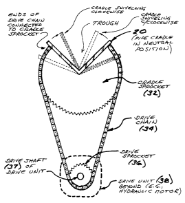
FIGURE 8 is a cross-section through the pipe cradle, conceptually illustrating
the
swivel means of the preferred embodiment of the invention, with the cradle
being in the neutral
(and swiveling modes shown in broken outline). The cradle sprocket of this
embodiment is
essentially a typical circular sprocket that has been notched out for
connection to the underside
of the cradle. The drive chain is fixed at each end to the upper region of the
cradle sprocket on
either side of the cradle, and wraps around a drive sprocket. The drive unit
is mounted below
the cradle such that it be raised as the cradle is raised, but also such that
rotation of the drive
unit's drive shaft will swivel the cradle about its axis, without the drive
unit itself rotating about
the drive shaft axis. In the preferred embodiment, this is accomplished by
mounting the drive
unit to a bracket or mounting plate pivotably connected to the lift arm (about
a transverse
horizontal axis), as may be understood from Figure 5. The axis of the drive
shaft thus remains
in the same orientation relative to the axis of the cradle regardless of the
angular position of the
cradle as the swing arm is moved from one position to another. Being connected
to and
laterally restrained by the swing arm, the mounting bracket cannot rotate
transversely, and thus
provides resistance for torque from the drive unit, thereby allowing the drive
unit to swivel the
cradle about its longitudinal axis.
*************************
It will be readily appreciated by those skilled in the art that various
modifications of the
present invention may be devised without departing from the essential concept
of the invention,
and all such modifications are intended to be included in the scope of the
claims appended
hereto.
In this patent document, the word "comprising" is used in its non-limiting
sense to mean
that items following that word are included, but items not specifically
mentioned are not
excluded. A reference to an element by the indefinite article "a" does not
exclude the possibility
that more than one of the element is present, unless the context clearly
requires that there be
one and only one such element.