Note: Descriptions are shown in the official language in which they were submitted.
CA 02472480 2004-07-13
WO 03/059410 PCT/US03/00935
COATING DISPENSING SYSTEM AND METHOD USING
A SOLENOID HEAD FOR COATING MEDICAL DEVICES
Related Applications
This application is a continuation-in-part of Application Number 09!895,415,
filed on July 2, 20'01.
Field of the Invention
The present invention generally regards the coating of work-pieces. More
particularly, the present invention regards a method and system for precision
coating
implantable medical appliances using a solenoid type fluid dispensing head.
Background Information
The positioning and deployment of medical appliances within a target site of a
patient is a common, often-repeated procedure of contemporary medicine. These
appliances
or implants are used for innumerable medical purposes including the
reinforcement of
recently re-enlarged lumens and the replacement of ruptured vessels.
Coatings are often applied to these medical appliances to increase their
effectiveness. These coatings may provide a number of benefits including
reducing the
trauma suffered during the insertion procedure, facilitating the acceptance of
the medical
appliance into the target site, and improving the post-procedure effectiveness
of the
appliance.
Expandable stems, stmt grafts, balloon delivery systems, and aneurism coils
are specific examples of medical appliances or implants that may be coated and
inserted
within the body. Expandable stems are tube-like medical appliances that often
have a mesh-
like structure designed to support the inner walls of a lumen. These stems are
typically
positioned within a lumen and, then, expanded to provide internal support for
it. Because of
the direct contact of the stent with the inner walls of the lumen, stems have
been coated with
various compounds and therapeutics to enhance their effectiveness. When this
coating is
haphazardly applied or has somehow been removed during the stmt's manufacture
or
delivery, the stent's effectiveness can be compromised. In'~ertain
circumstances, defective
CA 02472480 2004-07-13
WO 03/059410 PCT/US03/00935
implanted stems must be removed and reinserted through a second medical
procedure = an
unwanted result.
Indiscriminate coating methods such as dip-coating and spray-coating have
been used to coat stems as well as other medical appliances. These methods
are, however,
both wasteful and difficult to control. For example, dipping can result in non-
uniform
application of the coating to the appliance, thereby placing more coating at
one end or region
of the stmt and making it difficult to predict the dosage of therapeutic that
will be delivered
when the stmt or other appliance is implanted. The indiscriminate nature of
dipping is also
problematic as it may lead to the cracking and crumbling of coating at the
junctions, hinges,
and flexing members of the mesh-like stems. The coating that covers the hinged
portions of
the stmt is highly susceptible to exfoliate because, as the stmt is expanded,
intolerable
stresses may develop within the coating.
Figures l and 2 are illustrative of some of the concerns stemming from an
indiscriminate coating process like Blipping. In Figure 1, stmt 11 is shown in
a closed, pre-
deployment state. Here, stent 11 has been previously dipped in a vat of
therapeutic in the
direction of arrow 16. In other words, the right side of stmt 11 was the
leading edge entering
the dipping vat. As can be seen, the coating of stmt 11 is heavier on the
right side than on the
left side and covers each of the junctions 13 throughout the entire stmt 11.
As can also be
seen, the coating becomes progressively thicker and covers more of the space
between each
of struts 12 as you travel from the left side to the right side of stent 11.
This increasing
thickness of coating is indicative of a stmt that has been dipped and let
stand on one of its
ends as the coating dries and adheres to the stmt.
Figure 2 shows the unevenly coated stmt 11 of Figure 1 in an expanded state
as it may be after it is positioned within a body. As is evident, the
expansion of stmt 11 has
led to the cracking and crumbling of coating 15. Also evident is that the
coating has been
removed from most if not all of the junction points 13 after stmt 11 has been
expanded.
Summary of the Invention
A system and method for coating a medical appliance is provided. In accord
with one embodiment, a,system for applying a coating to a medical appliance
having
CA 02472480 2004-07-13
WO 03/059410 PCT/US03/00935
accessible patterned surfaces is provided. This system may include: a
processor, an appliance
support, and a solenoid type fluid dispensing head having an
electromagnetically controlled
valve. Jn this system the appliance support may be adapted to hold the medical
appliance and
to provide direct access for a coating to contact the exposed external
patterned surfaces of the
medical appliance. The solenoid type fluid dispensing head in this system may
move with
respect to the medical appliance and may be in communication with a source of
coating and
with the processor. The processor in this system may contain commands that
instruct the
solenoid type fluid dispensing head to force coating onto the accessible
patterned surfaces of
the medical appliance in a pattern that correlates with the accessible
patterned surfaces of the
medical appliance.
A method for applying a coating to a medical appliance having an accessible
patterned surface is also provided. In one embodiment this method may include
holding the
medical appliance, providing direct access to the external surfaces of the
medical appliance,
and receiving command signals that instruct a solenoid type fluid dispensing
head to force
coating onto the accessible patterned surfaces of the medical appliance in a
pattern that
correlates with the accessible patterned surfaces of the medical appliance.
Brief Description Of The Drawings
Figure 1 is an enlarged view of a stmt that has been unevenly coated with a
coating.
Figure 2 is an enlarged view of the stmt of Figure 1 in an expanded state, the
uneven coating being broken and cracked at the junction of the stmt's struts.
Figure 3 is a schematic view of a system for applying a coating to a medical
appliance using a solenoid type fluid dispensing head in accord with one
embodiment of the
present invention.
Figure 4 is a schematic view of a system for applying a coating to a medical
appliance using a solenoid type fluid dispensing head in accord with another
embodiment of
the present invention.
CA 02472480 2004-07-13
WO 03/059410 PCT/US03/00935
Figure 5 is a schematic view of a solenoid type fluid dispensing head,
appliance support, and microvision system in accord with another embodiment of
the present
invention.
Figure 6 is an enlarged view of the system shown in Figure 5 showing the
solenoid type fluid dispensing head and the microvision system.
Figure 7 is a schematic view of a system for applying a coating to a medical
appliance using a solenoid type fluid dispensing head in accord with another
embodiment of
the present invention.
Figure 8 is an enlarged cross-sectional view of a solenoid type fluid
dispensing
head in accord with another embodiment of the present invention.
DETAILED DESCRIPTION
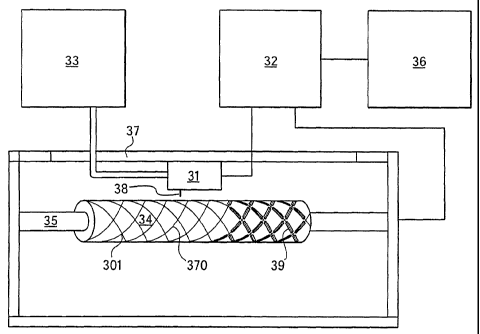
Figure 3 illustrates a system for coating a medical appliance using a solenoid
type fluid dispensing head in accord with one embodiment of the present
invention. In this
system, solenoid type fluid dispensing head 31 may be used to force coating
onto the
patterned surfaces of medical appliance 34. In this embodiment, solenoid type
fluid
dispensing head 31 may be placed in close proximity to medical appliance 34
and may be
moved back and forth along track 37 so that it may be able to coat the entire
external
patterned surface of medical appliance 34. Solenoid type fluid dispensing head
31 may be
controlled by, or at least receive signals from, processor 32, which may
instruct it to coat only
struts 370 of medical appliance 34. In other words, as solenoid type fluid
dispensing head 31
slides back and forth along track 37 and as medical appliance 34 is spun on
appliance support
35, solenoid type fluid dispensing head 31 may force coating onto struts 370
while
concurrently refraining from forcing coating into spaces between struts 370,
because coating
forced into these spaces would simply be wasted or result in errant deposits
of coating
elsewhere on medical appliance 34.
As can be seen in Figure 3, a portion 39 of struts 370 has already been
coated,
while another portion of struts 370 has not been coated. Also apparent in
Figure 3 is that
junctions 301 of struts 370 have not been coated. Figure 3 also illustrates
stream of coating
CA 02472480 2004-07-13
WO 03/059410 PCT/US03/00935
38 ejected from'solenoid type fluid dispensing head 31 prior to contact with
medical
appliance 34.
In Figure 3, the coating source 33 may be in fluid communication with
solenoid type fluid dispensing head 31 and may be used to supply coating to
solenoid type
fluid dispensing head 31. Storage media 36 may be in communication with
processor 32 and
may be used to store and provide instructions for processor 32 and coating
source 33 for
coating medical appliance 34. Storage media 36 may be one of numerous types of
available
storage media including both volatile (i.e. RAM) and non-volatile storage
devices (i.e. ROM,
CD ROM, EEPROM, Magnetic Media, etc.). The pre-programmed instructions or
other
retained data may be unique to each medical appliance 34 and may account for
the unique
external pattern and precise dimensions of each medical appliance 34 that may
be coated by
solenoid type fluid dispensing head 31. Storage media 36 may also hold unique
instruction
sets for many different medical appliances or may be provided with a media
receptacle such
as a disk drive that accommodates different recordable media, each recordable
media holding
a unique instruction set for a single medical appliance or a set of
instructions for multiple
medical appliances.
As mentioned above, medical appliance 34 in this embodiment may be rotated
by appliance support 35 in order to expose different sides of medical
appliance 34 to solenoid
type fluid dispensing head 31. Consequently, through the coordinated movement
of solenoid
type fluid dispensing head 31 on track 37 and medical appliance 34 in
appliance support 35,
all external portions of medical appliance 34 may be exposed to and coated by
the nozzle (not
shown) of solenoid type fluid dispensing head 31.
In an alternative embodiment, wherein the medical appliance is flat or
otherwise linear, the appliance support configuration may be different than
that described
above. Here, the appliance support may provide for movement of the appliance
in both the x
and y planes while the solenoid type fluid dispensing head moves back and
forth overhead in
order to reach the entire surface of the medical device.
As described above, solenoid type fluid dispensing head 31 may be in fluid
communication with coating source 33. Coating source 33 may contain any one of
several
possible coatings to be placed on medical appliance 34. These coatings may
include
CA 02472480 2004-07-13
WO 03/059410 PCT/US03/00935
paclitaxel, a polymer with a suspended therapeutic, a non-thrombogenic agent,
a lubricious
material, a non-slippery material, a radiopaque agent, a radioactive agent,
and a magnetic
signature agent. These coatings may also include: pharmaceutically active
compounds,
proteins, cells, oligonucleotides, ribozymes, anti-sense oligonucleotides, DNA
compacting
agents, gene/vector systems (i.e., any vehicle that allows for the uptake and
expression of
nucleic acids), nucleic acids (including, for example, recombinant nucleic
acids; naked DNA,
cDNA, RNA; genomic DNA, cDNA or RNA in a non-infectious vector or in a viral
vector
and which further may have attached peptide targeting sequences; antisense
nucleic acid
(RNA or DNA); and DNA chimeras which include gene sequences and encoding for
ferry
proteins such as membrane translocating sequences ("MTS") and herpes simplex
virus-1
("VP22")), and viral, liposomes and cationic and anionic polymers and neutral
polymers that
are selected from a number of types depending on the desired application. Non-
limiting
examples of virus vectors or vectors derived from viral sources include
adenoviral vectors,
herpes simplex vectors, papilloma vectors, adeno-associated vectors,
retroviral vectors, and
the like. Non-limiting examples of biologically active solutes include anti-
thrombogenic
agents such as heparin, heparin derivatives, urokinase, and PPACK
(dextrophenylalanine
proline arginine chloromethylketone); antioxidants such as probucol and
retinoic acid;
angiogenic and anti-angiogenic agents and factors; agents blocking smooth
muscle cell
proliferation such as rapamycin, angiopeptin, and monoclonal antibodies
capable of blocking
smooth muscle cell proliferation; anti-inflammatory agents such as
dexamethasone,
prednisolone, corticosterone, budesonide, estrogen, sulfasalazine, acetyl
salicylic acid, and
mesalamine; calcium entry blockers such as verapamil, diltiazem and
nifedipine;
antineoplastic / antiproliferative / anti-mitotic agents such as paclitaxel, 5-
fluorouracil,
methotrexate, doxorubicin, daunorubicin, cyclosporine, cisplatin, vinblastine,
vincristine,
epothilones, endostatin, angiostatin and thymidine kinase inhibitors;
antimicrobials such as
triclosan, cephalosporins, aminoglycosides, and nitorfurantoin; anesthetic
agents such as
lidocaine, bupivacaine, and ropivacaine; nitric oxide (NO) donors such as
lisidomine,
molsidomine, L-arginine, NO-protein adducts, NO-carbohydrate adducts,
polymeric or
oligomeric NO adducts; anti-coagulants such as D-Phe-Pro-Arg chloromethyl
ketone, an
RGD peptide-containing compound, heparin, antithrombin compounds, platelet
receptor
CA 02472480 2004-07-13
WO 03/059410 PCT/US03/00935
antagonists, anti-thrombin antibodies, anti-platelet receptor antibodies,
enoxaparin, hirudin,
Warafin sodium, Dicurnarol, aspirin, prostaglandin inhibitors, platelet
inhibitors and tick
antiplatelet factors; vascular cell growth promotors such as growth factors,
growth factor
receptor antagonists, transcriptional activators, and translational promotors;
vascular cell
growth inhibitors such as growth factor inhibitors, growth factor receptor
antagonists,
transcriptional repressors, translational repressors, replication inhibitors,
inhibitory
antibodies, antibodies directed against growth factors, bifunctional molecules
consisting of a
growth factor and a cytotoxin, bifunctional molecules consisting of an
antibody and a
cytotoxin; cholesterol-lowering agents; vasodilating agents; agents which
interfere with
endogeneus vascoactive mechanisms; survival genes which protect against cell
death, such as
anti-apoptotic Bcl-2 family factors and Akt kinase; and combinations thereof.
Cells may be
of human origin (autologous or allogenic) or from an animal source
(xenogeneic), genetically
engineered if desired. The delivery medium is formulated as needed to maintain
cell function
and viability. Any modifications are routinely made by one skilled in the art.
Polynucleotide sequences useful in practice of the invention include DNA or
RNA sequences having a therapeutic effect after being taken up by a cell.
Examples of
therapeutic polynucleotides include anti-sense DNA and RNA; DNA coding for an
anti-sense
RNA; or DNA coding for tRNA or rRNA to replace defective or deficient
endogenous
molecules. The polynucleotides of the invention may also code for therapeutic
proteins or
polypeptides. A polypeptide is understood to be any translation product of a
polynucleotide
regardless of size, and whether glycosylated or not. Therapeutic proteins and
polypeptides
include as a primary example, those proteins or polypeptides that can
compensate for
defective or deficient species in an animal, or those that act through toxic
effects to limit or
remove harmful cells from the body. In addition, the polypeptides or proteins
that may be
injected, or whose DNA may be incorporated, include without limitation,
angiogenic factors
and other molecules competent to induce angiogenesis, including acidic and
basic fibroblast
growth factors, vascular endothelial growth factor, hif 1, epidermal growth
factor,
transforming growth factor a and (3, platelet-derived endothelial growth
factor, platelet-
derived growth factor, tumor necrosis factor a, hepatocyte growth factor and
insulin like
growth factor; growth factors; cell cycle inhibitors including CDK inhibitors;
anti-restenosis
CA 02472480 2004-07-13
WO 03/059410 PCT/US03/00935
agents, if~cluding p 15, p 16, p 18, p 19, p21, p27, p53, p57, Rb, nFkB and
E2F decoys,
thymidine kinase ("TK") and combinations thereof and other agents useful for
interfering
with cell proliferation, including agents for treating malignancies; and
combinations thereof.
Still other useful factors, which may be provided as polypeptides or as DNA
encoding these
polypeptides, include monocyte chemoattractant protein ("MCP-1 "), and the
family of bone
morphogenic proteins ("BMP's"). The known proteins include BMP-2, BMP-3, BMP-
4,
BMP-5, BMP-6 (Vgr-1), BMP-7 (OP-1), BMP-8, BMP-9, BMP-10, BMP-11, BMP-12,
BMP-13, BMP-14, BMP-15, and BMP-16. Currently preferred BMP's are any of BMP-
2,
BMP-3, BMP-4, BMP-5, BMP-6 and BMP-7. These dimeric proteins may be provided
as
homodimers, heterodimers, or combinations thereof, alone or together with
other molecules.
Alternatively or, in addition, molecules capable of inducing an upstream or
downstream
effect of a BMP may be provided. Such molecules include any of the "hedgehog"
proteins, or
the DNA's encoding them.
Another alternative coating material is any conductive material, which may be
coated on the medical appliance to provide electrical conductivity for either
power or signal
functions to different parts of the medical appliance. For instance, an
electrically conductive
stripe may be applied to a catheter to enable a source of power at a proximal
end of the
catheter to provide power to a remote application at a distal end of the
catheter. Additionally,
the solenoid type, fluid dispensing head may be utilized to coat a previously
applied
conductive material with an insulating material to thereby electrically
isolate the conductive
material.
A solenoid type fluid dispensing head may enable coating with more viscous
materials than alternative methods because it may have a larger orifice and
nozzle through
which the coating fluids travel. Solenoid type fluid dispensing heads may
enable coating
with materials having viscosities from 1 centipoise (viscosity equal to water)
to 1500
centipoise. Higher viscosities may also be possible using higher pressures for
the coating
source. An exemplary pressure for the coating source is 30 pounds per square
inch above
atmospheric pressure. Highly viscous materials may be preferable for coating
medical
appliances. Coating materials may become viscous due to a high solids content,
which may
be due to a higher concentration of therapeutic. A higher concentration of
therapeutic may be
CA 02472480 2004-07-13
WO 03/059410 PCT/US03/00935
preferable from a clinical standpoint in that it may make the medical
appliance more
effective. Additionally, coatings having high concentrations of therapeutic
(and therefore
high viscosity) may require fewer coating steps, and therefore require less
time to produce.
Therefore, higher drug loads may be applied to the medical appliance with
fewer coats which
may be applied in less time.
The solenoid type fluid dispensing head in this embodiment is preferably
programmed to coat in a precise manner, allowing coating to be applied in a
complex pattern,
matching the complex pattern of the medical appliance. It may also be
preferred that the
stream of coating forced from the solenoid type fluid dispensing head be small
in relation to
the target area of the medical appliance to allow for a high degree of
precision in coating the
target. Precision coating of the medical appliance enables economical use of
coating
materials.
In an alternative embodiment, rather than having the coating material
deposited in one coat or layer around the entire device, the solenoid type
fluid dispensing
head may coat the medical appliance with different layers of different
thicknesses in different
regions of the appliance as may be desirable for the subsequent use of the
appliance. In doing
so, different concentrations of therapeutic may be deposited in different
regions of the
medical appliance.
The coatings that may be applied by a solenoid type fluid dispensing head may
also include: lubricious coatings to reduce the stress exerted on the stmt
during the stmt's
deployment; radiopaque coatings for identifying the location of stems after
implantation
using traditional radiography techniques; radioactive agents that are useful
in preventing
tissue regrowth in and around implanted stems; and magnetic coatings that
enable
identification of the location of the implanted stmt using Magnetic Resonance
Imaging
(MRI) techniques. These magnetic coatings may be obtained using ferritic
powders or
paramagnetic powders such as Gadolinium or Disprosium.
Another useful application of this precise coating method may be to convey
information, or an identification code on the appliance itself. This
information or code may
then be used to identify the source of the medical appliance and other history
related to it for
CA 02472480 2004-07-13
WO 03/059410 PCT/US03/00935
tracking purposes. Once implanted, the code, which may be a bar code, could be
read though
radiography, MRI or any other suitable invasive or non-invasive procedure.
Figure 4 shows a system for coating a medical appliance using a solenoid type
fluid dispensing head and means for redirecting the material forced from the
solenoid type
fluid dispensing head prior to impacting the targeted medical appliance in
accord with an
alternative embodiment of the present invention. In this embodiment the
solenoid type fluid
dispensing head 41 may be used to coat a medical appliance 44 as described
above.
However, in this embodiment, after coating stream 46 has been forced from
solenoid type
fluid dispensing head 41, it may be redirected or influenced by redirecting
means 43.
Redirecting means 43 may be implemented using a battery or power source
controlled by
processor 42 to apply a voltage between nozzle 49 and appliance support 45.
Alternative
methods for influencing the path or traj ectory of the coating once it has
been forced from
solenoid type fluid dispensing head 41 may also be possible. By employing
redirecting
means 43, the distance that the head may travel may be reduced. Similarly, the
head may not
need to be moved back and forth as quickly as in earlier embodiments as the
gross
adjustments may be completed with the movement of solenoid type fluid
dispensing head 41
along a track (not shown) while the fine adjustments of the forced coating may
be controlled
by redirecting means 43.
In this embodiment, solenoid type fluid dispensing head 41 may be controlled
by processor 42, which may also control appliance support 45 and redirecting
means 43.
Here, solenoid type fluid dispensing head 41, working in concert with
appliance support 45,
which may hold, move, and rotate the medical appliance 44, may coat each of
the struts 47
but not the junctions 48 as shown in Figure 4. Redirecting means 43 may be
mounted so that
coating stream 46 forced from solenoid type fluid dispensing head 41 receives
a positive or
negative charge from nozzle 49 which is connected to redirecting means 43. An
opposite
charge is applied by redirecting means 43 to the struts of medical appliance
44 through
appliance support 45. Coating stream 46, having an opposite charge, would
therefore be
attracted to the struts of medical appliance 44.
Figure 5 shows an alternative embodiment of the present invention wherein
solenoid type fluid dispensing head 51 is in fluid communication with coating
source 53. In
to
CA 02472480 2004-07-13
WO 03/059410 PCT/US03/00935
Figure 5', solenoid type fluid dispensing head 51 is arranged above medical
appliance 54
which is arranged on appliance support 55. Solenoid type fluid dispensing head
51 is
adjustable up and down by nozzle height adjustment 58 to increase or decrease
the distance
between solenoid type fluid dispensing head 51 and medical appliance 54. In
one exemplary
embodiment, the distance between solenoid type fluid dispensing head 51 and
medical
appliance 54 may depend on both the diameter of the nozzle (not shown) of
solenoid type
fluid dispensing head 51 and the viscosity of the fluid being applied to
medical appliance 54.
An exemplary range of values for the diameter of the nozzle is from 1 micron
to 5
millimeters. Solenoid type fluid dispensing head 51 may also move in the
direction of the
longitudinal axis of medical appliance 54 during the coating process at the
command of the
processor.
Also shown in Figure 5 is vision system 52 which is a microvision system or
micro-tracking vision system. Vision system 52 communicates with a processor
(not shown)
to control the movements of solenoid type fluid dispensing head 51, the
rotation of medical
appliance 54, and the ejection of material from solenoid type fluid dispensing
head 51.
Vision system 52 may be used in any one of, or any combination of, the
following ways.
First, vision system 52 may be used to determine the position and orientation
of medical
appliance 54 by identifying an identifiable feature on medical appliance 54.
Second, vision
system 52 may be used to determine the position and orientation of the nozzle
of solenoid
type fluid dispensing head 51 by observing the solenoid type fluid dispensing
head directly or
by observing a test coating ejected onto a test piece for the purpose of
locating solenoid type
fluid dispensing head 51. Finally, vision system 52 may be used to monitor the
coating of
medical appliance 54 by solenoid type fluid dispensing head 51 as the coating
is proceeding.
Figure 5 illustrates appliance support 55, which includes both x-y positioning
table 56 and mandrel 57. X-y positioning table 56 is used to position medical
appliance 54
prior to, or during, the coating process. The x-y plane is defined as the
plane perpendicular to
the direction of the nozzle (not shown) of solenoid type fluid dispensing head
51. X-y
positioning table may be either manually controlled or processor controlled.
Mandrel 57
holds medical appliance 54, which in Figure 5 is a stmt, in a weak friction
fit. Mandrel 57 in
an exemplary embodiment is stainless steel with a teflon coating to prevent
accumulation of
11
CA 02472480 2004-07-13
WO 03/059410 PCT/US03/00935
any excess coating and to facilitate cleaning of mandrel 57. Additionally,
mandrel 57 may be
painted black to improve contrast between mandrel 57 and medical appliance 54
and to
thereby improve the quality of the image collected by vision system 52.
Figure 6 is an enlargement of the exemplary embodiment shown in Figure 5.
Solenoid type fluid dispensing head 61 is shown in valve mounting clamp 63.
Also shown in
Figure 6 is vision system 62, which operates, as noted above, to observe the
deposition of the
coating onto medical appliance 64 as well as to perform numerous other
functions including
verifying the position of solenoid type fluid dispensing head 61 and medical
appliance 64. In
this embodiment, vision system 62 may be used for quality control, for
orienting medical
appliance 64 with respect to solenoid type fluid dispensing head 61, and for
tracking the
external pattern of medical appliance 64 during the coating process.
Therefore, the processor
may use information received from vision system 62 to adjust the commands it
issues to
solenoid type fluid dispensing head 61 during the coating process. Also
illustrated in greater
detail in Figure 6 is appliance support 65, which includes mandrel 67, holding
in this
exemplary embodiment a stmt as medical appliance 64. The position of mandrel
67 is
adjustable by appliance support 65 in response to the processor using data
collected by vision
system 62. Mandrel 67 is rotatable before and during the coating process to
bring all exposed
surfaces of medical appliance 64 adjacent to solenoid type fluid dispensing
head 61. When
an exposed surface of medical appliance 64 that requires coating is adjacent
to the solenoid
type fluid dispensing head 61, solenoid type fluid dispensing head 61 is
activated by the
processor to open and allow the coating material, which is under pressure, to
flow through
solenoid type fluid dispensing head 61 and through nozzle 68 onto medical
appliance 64.
Nozzle 68 is adapted to provide maximum control over the coating material to
allow accurate
coating of medical appliance 64. The design of nozzle 68 may vary depending on
the
viscosity of the coating material. Alternatively, two solenoid type fluid
dispensing heads
may be connected to one nozzle 68 to provide the ability to coat medical
appliance 64 with
two different coatings. The different coatings may consist of different
concentrations of the
same therapeutic, the same therapeutic dissolved in different polymers or in
different
suspension fluids having different release rates, different therapeutics, or a
combination of
12
CA 02472480 2004-07-13
WO 03/059410 PCT/US03/00935
therapeutic materials and non-therapeutic materials (for instance lubricious
materials), of any
type noted above.
Figure 7 shows a system for coating a medical appliance using a solenoid type
fluid dispensing head in accord with another alternative embodiment of the
present invention.
Solenoid type fluid dispensing head 71 is shown in Figure 7 as mounted on
support 77 and in
fluid communication with coating source 73. Also evident in Figure 7 are
appliance support
75, sprayer 76, first sprayer source 78, and second sprayer source 79.
In this embodiment, rather than applying a coating material with solenoid type
fluid dispensing head 71, a masking material may be applied. Once applied in a
desirable
pattern on medical appliance 74, an etchant may then be applied with sprayer
76 to etch the
exposed portions of medical appliance 74 thereby etching the appliance in all
regions not
covered by the masking material. Then, once all the required etching is
completed the
masking material may be removed.
Sprayer 76 in this embodiment may be mounted on support 77 and may be
able to slide back and forth along support 77 during the spraying activities.
Sprayer 76 may
also be in fluid communication with first sprayer source 78 and second sprayer
source 79,
similar to the coating sources described above, which may store different
etching materials
for use in the process.
Sprayer 76 in this embodiment may also be used for other indiscriminate
spraying applications as well, including direct etching, cleaning, and drying
medical
appliance 74. In a direct etching application, solenoid type fluid dispensing
head 71 may be
used to apply a corrosive material onto medical appliance 74. Here the
corrosive material
may be used to selectively etch or groove portions of the various struts of
medical appliance
74. Alternatively, solenoid type fluid dispensing head 71 may apply a first
material to
specific areas to be etched and, then, may apply a second material, which
reacts with the first
material, to etch the desired portions of rriedical appliance 74.
Figure 8 is an enlarged cross-sectional view of a solenoid type fluid
dispensing
head in accord with the present invention. Solenoid type fluid dispensing head
81 is a
normally closed electromagnetically controlled valve having inlet 82 which
connects to a
pressurized coating source (not shown). The coating does not normally flow
through
13
CA 02472480 2004-07-13
WO 03/059410 PCT/US03/00935
solenoid type flyid dispensing head 81 because poppet 83 seals the passage to
nozzle 87
under the influence of a spring (not shown). However, when a voltage is
applied across
contacts 84, current flows through coil 85, and an electromagnetic force is
consequently
applied to poppet 83. Poppet 83 is thereby induced to move in the direction of
arrow 86,
opening the passage and allowing the coating to flow. When poppet 83 is in the
open
position, the coating flows out through nozzle 87 onto the medical appliance
(not shown).
The wetted surfaces of solenoid type fluid dispensing head 81 are defined as
those surfaces
which contact the coating as it flows through solenoid type fluid dispensing
head 81. In one
alternative embodiment, the wetted surfaces are made of materials which are
resistant to
dissolving by Toluene and alcohol-based materials. The wetted surfaces may be
constructed
of EPDM, PEEK; stainless steel, glass, ceramic, PPS, epoxy, or any other
appropriate
material. Applying a voltage at contact 84 induces a continuous flow of
coating out of nozzle
87, thereby enabling a thicker coating on the medical appliance with fewer
passes required by
solenoid type fluid dispensing head 81 over the specified portions of the
medical appliance to
achieve the desired coating thickness. Nozzle 87 is a non-contact nozzle
designed to eject the
coating material in a controlled fashion from a distance at the medical
appliance. The
distance between the nozzle and the medical appliance may depend on the
viscosity of the
fluid being ejected. The diameter of the nozzle may be in the range of 1
micron to 5
millimeters.
A solenoid type fluid dispensing head for coating a medical appliance is
provided herein. While several embodiments have been discussed, others, within
the
invention's spirit and scope, are also plausible. For example, while one
solenoid type fluid
dispensing head is described in each of the above embodiments more than one
solenoid type
fluid dispensing head may also be employed. In this alternative embodiment,
the multiple
solenoid type fluid dispensing heads may work synchronously and asynchronously
and may
be ganged together to coat several medical appliances simultaneously.
14