Language selection

Search

Patent 2472632 Summary

Third-party information liability

Some of the information on this Web page has been provided by external sources. The Government of Canada is not responsible for the accuracy, reliability or currency of the information supplied by external sources. Users wishing to rely upon this information should consult directly with the source of the information. Content provided by external sources is not subject to official languages, privacy and accessibility requirements.

Claims and Abstract availability

Any discrepancies in the text and image of the Claims and Abstract are due to differing posting times. Text of the Claims and Abstract are posted:

  • At the time the application is open to public inspection;
  • At the time of issue of the patent (grant).
(12) Patent: (11) CA 2472632
(54) English Title: CURTAIN HOLDER
(54) French Title: SUPPORT DE RIDEAU
Status: Granted
Bibliographic Data
Abstracts

English Abstract

A curtain holder has a body formed from two pivotally connected segments and defining a curtain confining enclosure. Each of the segments has a connection end and a remote end. A mounting is provided for mounting the body to a vertical surface. A hinge pivotally connects the connection ends of the segments. The segments are pivotally movable between an open position in which the remote end of each of the segments are spaced apart to permit insertion of a curtain into the curtain confining enclosure and a closed position in which the remote end of the segments are closely spaced.


French Abstract

Support de rideau muni d'un corps formé de deux segments reliés par pivot et formant une enceinte de confinement pour le rideau. Chaque segment comporte une extrémité de raccordement et une extrémité distale. Un support est prévu pour le montage du corps sur une surface verticale. Une charnière relie les extrémités de raccordement des segments. Ces derniers peuvent pivoter entre une position ouverte où l'extrémité distale de chaque segment est éloignée de l'autre pour permettre l'insertion d'un rideau dans l'enceinte de confinement du rideau, et une position fermée où les extrémités distales des deux segments sont rapprochées.

Claims

Note: Claims are shown in the official language in which they were submitted.


6
THE EMBODIMENT OF THE INVENTION IN WHICH AN EXCLUSIVE
PROPERTY OR PRIVILEGE IS CLAIMED ARE DEFINED AS FOLLOWS:
1. A curtain holder, comprising:
an annular body formed from two connected segments of unequal size and
defining a curtain confining enclosure, each of the segments having a
connection end and
a remote end and the annular body having a peripheral edge;
a mounting plate having a pair of opposed parallel surfaces for mounting the
annular body to a vertical surface with a first of the opposed parallel
surfaces flush
against the vertical surface, the annular body being pivotally mounted to the
mounting
plate about a pivot axis extending parallel to the mounting plate, the
peripheral edge of
the annular body resting against a second of the opposed parallel surfaces of
the
mounting plate and biased into a position extending perpendicularly from the
mounting
plate;
a hinge offset from and independent of the mounting plate, the hinge pivotally

connecting the connection ends of the segments for pivotal movement about a
substantially vertical pivot axis, such that the segments are pivotally
movable relative to
each other between an open position in which the remote end of each of the
segments are
spaced apart to permit insertion of a curtain into the curtain confining
enclosure and a
closed position in which the remote end of the segments are closely spaced;
and
the remote end of the segments has a first engagement and the remote end of
another of the segments has a second engagement, the first engagement and the
second
engagement engaging when the segments are in the closed position.

2. The curtain holder as defined in Claim 1, wherein the first engagement and
the second
engagement have a magnetic engagement.

3. The curtain holder as defined in Claim 1, wherein the first engagement and
the second
engagement have a mating engagement.


7
4. The curtain holder as defined in Claim 1, wherein the first engagement and
the second
engagement have an overlapping engagement.

5. The curtain holder as defined in Claim 1, wherein the remote end of one of
the
segments has a decorative member which conceals the first engagement and the
second
engagement when the segments are in the closed position.

Description

Note: Descriptions are shown in the official language in which they were submitted.


CA 02472632 2004-06-10

1
TITLE OF THE INVENTION:
Curtain holder

FIELD OF THE INVENTION
The present invention relates to a curtain holder.
BACKGROUND OF THE INVENTION
Curtain holders are used to hold shower curtains together at one side of a
shower
enclosure and are used to hold curtains together at one side of a window.
SUMMARY OF THE INVENTION
The present invention relates to a novel configuration of curtain holder.

According to the present invention there is provided a curtain holder, which
has a
body formed from two connected segments and defining a curtain confining
enclosure. Each
of the segments has a connection end and a remote end. Means are provided for
mounting
the body to a vertical surface. A hinge pivotally connects the connection ends
of the
segments. The segments are pivotally movable between an open position in which
the
remote end of each of the segments are spaced apart to permit insertion of a
curtain into the
curtain confining enclosure and a closed position in which the remote end of
the segments
are closely spaced.

BRIEF DESCRIPTION OF THE DRAWINGS
These and other features of the invention will become more apparent from the
following description in which reference is made to the appended drawings, the
drawings are
for the purpose of illustration only and are not intended to in any way limit
the scope of the
invention to the particular embodiment or embodiments shown, wherein:
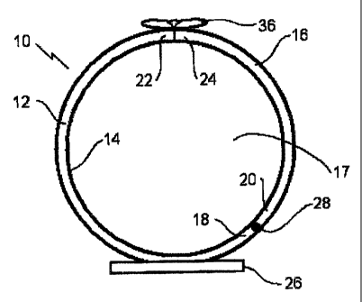
FIGURE 1 is a top plan view of the curtain holder in the closed position.
FIGURE 2 is a top plan view of the curtain holder in the open position.
FIGURE 3 is a side view of the curtain holder being used to hold back a
curtain.
FIGURE 4 is an exlpoded top view in partial section of interlocking
components.
FIGURE 5 is a side view of the curtain holder of FIGURE 1 with an alternative


CA 02472632 2004-06-10

2
hinge.
FIGURE 6 in an exploded top plan view of alternative mounting means and
another
alternative hinge.
FIGURE 7 is an exploded top plan views of another alternative hinge.
FIGURES 8 through 11 are exploded views of alternative interlocking
components.
FIGURES 12 through 15 and 17 and 18 are top plan views of alternative body
shapes.
FIGURE 16 is a side perspective view of an alternative body shape.
DETAILED DESCRIPTION OF THE PREFERRED EMBODIMENT
The preferred embodiment, a curtain holder generally identified by reference
numeral
10, will now be described with reference to FIGURES 1 through 4 and 18.

Structure and Relationship of Parts:
Referring now to FIGURE 1, curtain holder 10 is shown. An annular body 12 is
formed from two connected segments, 14 and 16 that define a curtain confining
enclosure
17. Each segment 14 and 16 has a connection end 18 and 20 respectively, and a
remote end
22 and 24 respectively. A mounting plate 26 provides means for mounting
annular body 12
to a vertical surface 27, as shown in FIGURE 3. Referring again to FIGURE 1, a
hinge 28
is offset from, and independent of, mounting plate 26. Referring to FIGURE 18,
hinge 28
may also be located in the center of mounting plate 26. Referring again to
FIGURE 1 hinge
28 pivotally connects connection ends 18 and 20 of segments 14 and 16, such
that segments
14 and 16 are pivotally movable between an open position shown in FIGURE 2 and
a closed
position shown in FIGURE 1. Referring now to FIGURE 2, in the open position,
remote
ends 22 and 24 are spaced apart to permit insertion of a curtain 30 into
curtain confining
enclosure 17, as shown in FIGURE 3. Referring now to FIGURE 1, in the closed
position,
remote ends 22 and 24 are closely spaced. As can be seen from the top view
provided in
FIGURES 1 and 2, hinge 28 pivots about a substantially vertical pivot axis.
Because hinge
28 is offset from mounting plate 26, segments 14 and 16 are unequal in size to
allow remote
ends 22 and 24 to meet opposite mounting plate 26.

Referring to FIGURE 4, remote ends 22 and 24 have first and second engagements


CA 02472632 2004-06-10

3
32 and 34 respectively, such that first engagement 32 and second engagement 34
matingly
engage when segments 14 and 16 are in the closed position. Remote end 24 has a
decorative
member 36 which conceals first engagement 32 and second engagement 34 when
segments
14 and 16 are in the closed position.
Operation:
The operation of curtain holder 10 will now be discussed with reference to
FIGURES 1 through 4. Curtain holder 10 is mounted on a vertical surface 27 as
shown in
FIGURE 3. Body 12 is originally in the closed position as shown in FIGURE 1,
with
remote ends 22 and 24 engaged. Referring now to FIGURE 2, segment 16 is
pivoted about
hinge 28 into the opened position. Referring now to FIGURE 3, curtain 30 is
placed within
the opening created by pivoting segment 16 about hinge 28, and segment 16 is
then returned
to its original position such that remote ends 22 and 24 are engaged. Curtain
30 is removed
by repeating the process.
Variations:
Variations from the preferred embodiment will now be discussed with reference
to
FIGURES 5 through 18.

Pivoting about a horizontal pivot axis:
Referring to FIGURE 4, hinge 28 may pivot about a substantially horizontal
pivot
axis. As shown, segment 16 is adapted to be lifted up, and first engagement 32
is adapted to
receive second engagement 34 with an opening in the top such that segment 16
may be easily
lifted.
Biasing to a closed position:
Referring to FIGURE 6, segments 14 and 16 are biased toward the closed
position
by a spring 38, which may be replaced by a different resilient material.
Spring 38 may be
located on the outside of annular body 12, as shown, or on the inside.
Alternatively, spring
38 maybe included within hinge 28.

Use of a "living hinge":


CA 02472632 2004-06-10

4
Referring now to FIGURE 7, annular body 12 is made from polymer plastic and
hinge 40 is a living hinge formed in the polymer plastic which functions based
upon the
flexure properties of the polymer plastic. A living hinge is a thin flexible
web of material
that joins two rigid bodies together.
Use of Alternative Engagements:
Referring to FIGURE 8, first engagement 32 and second engagement 34 engage
each other in a male/female fashion with a projection 46 engaging an
indentation 48 such
that second engagement 34 must be pushed back or first engagement 32 pulled
forward to
release the engagement. Referring to FIGURE 9, first and second engagements 32
and 34
engage in an overlapping fashion, such that, when engaged, annular body 12 is
continuous.
There may or may not be a connection that resists disengagement. Referring to
FIGURE 10,
first and second engagements 32 and 34 engage in an overlapping fashion, and
have
projections 50 that, when engaged, keep annular body 12 closed. Referring to
FIGURE 11,
first and second engagements 32 and 34 have a magnetic engagement using
magnetic
components 42 and 44. Magnetic components 42 and 44 may have opposite
polarized ends
directed toward each other, or one may be a magnet and the other a conducting
metal.
FIGURE 11 shows first and second engagements 32 and 34 meeting directly with
no
overlap or male/female connection, It will be understood that this arrangement
is possible
without magnetic components 42 and 44, which magnetic components 42 and 44 may
be
integrated into other means of engagement.

Alternative mounting means:
Referring to FIGURE 5, mounting plate 26 is shown to be tapered on the sides,
rather than rectangular as shown for example in FIGURE 1. Referring to FIGURE
7,
mounting plate 26 is integral toannular body 12. In addition, instead of
screws, an adhesive
could be used to attach mounting plate 26 to vertical surface 27.

Alternative shapes of body 12:
Referring now to FIGURES 12 through 16, annular body 12 need not be circular
in
shape. FIGURE 12 shows body 12 as an octagon. FIGURE 13 shows body 12 as a
sleeve.
FIGURE 14 shows body 12 as an oval. FIGURE 15 shows body 12 adapted to engage,
but
M ;, ri N =~-


CA 02472632 2011-08-26

not entirely enclose, a curtain. For this embodiment, engagement means are
unneccesary.
FIGURE 16 shows body as a square. FIGURES 17 and 18 show two other possible
shapes
for body 12.

5 In this patent document, the word "comprising" is used in its non-limiting
sense to mean that items following the word are included, but items not
specifically
mentioned are not excluded. A reference to an element by the indefinite
article "a" does
not exclude the possibility that more than one of the element is present,
unless the context
clearly requires that there be one and only one of the elements.
The following claims are to be understood to include what is specifically
illustrated and described above, what is conceptually equivalent, and what can
be
obviously substituted. The scope of the claims should not be limited by the
preferred
embodiments set forth in the examples, but should be given the broadest
interpretation
consistent with the description as a whole.

Representative Drawing
A single figure which represents the drawing illustrating the invention.
Administrative Status

For a clearer understanding of the status of the application/patent presented on this page, the site Disclaimer , as well as the definitions for Patent , Administrative Status , Maintenance Fee  and Payment History  should be consulted.

Administrative Status

Title Date
Forecasted Issue Date 2012-08-14
(22) Filed 2004-06-10
(41) Open to Public Inspection 2005-12-10
Examination Requested 2009-06-10
(45) Issued 2012-08-14

Abandonment History

There is no abandonment history.

Payment History

Fee Type Anniversary Year Due Date Amount Paid Paid Date
Application Fee $200.00 2004-06-10
Maintenance Fee - Application - New Act 2 2006-06-12 $50.00 2006-05-15
Maintenance Fee - Application - New Act 3 2007-06-11 $50.00 2007-05-23
Maintenance Fee - Application - New Act 4 2008-06-10 $50.00 2008-06-05
Request for Examination $400.00 2009-06-10
Maintenance Fee - Application - New Act 5 2009-06-10 $100.00 2009-06-10
Maintenance Fee - Application - New Act 6 2010-06-10 $100.00 2010-06-07
Maintenance Fee - Application - New Act 7 2011-06-10 $100.00 2011-06-01
Final Fee $150.00 2012-04-16
Maintenance Fee - Application - New Act 8 2012-06-11 $100.00 2012-06-06
Maintenance Fee - Patent - New Act 9 2013-06-10 $100.00 2013-06-06
Maintenance Fee - Patent - New Act 10 2014-06-10 $125.00 2014-06-06
Maintenance Fee - Patent - New Act 11 2015-06-10 $125.00 2015-05-22
Maintenance Fee - Patent - New Act 12 2016-06-10 $125.00 2016-06-10
Maintenance Fee - Patent - New Act 13 2017-06-12 $325.00 2018-05-18
Maintenance Fee - Patent - New Act 14 2018-06-11 $125.00 2018-05-18
Maintenance Fee - Patent - New Act 15 2019-06-10 $425.00 2019-11-04
Maintenance Fee - Patent - New Act 16 2020-06-10 $225.00 2020-05-15
Maintenance Fee - Patent - New Act 17 2021-06-10 $229.50 2021-10-25
Late Fee for failure to pay new-style Patent Maintenance Fee 2021-10-25 $150.00 2021-10-25
Back Payment of Fees 2021-10-25 $5.50 2021-10-25
Maintenance Fee - Patent - New Act 18 2022-06-10 $229.04 2022-06-07
Back Payment of Fees 2023-06-02 $0.17 2023-06-02
Maintenance Fee - Patent - New Act 19 2023-06-12 $236.83 2023-06-02
Owners on Record

Note: Records showing the ownership history in alphabetical order.

Current Owners on Record
KOZIAK, ZENON
Past Owners on Record
None
Past Owners that do not appear in the "Owners on Record" listing will appear in other documentation within the application.
Documents

To view selected files, please enter reCAPTCHA code :


To view images, click a link in the Document Description column. To download the documents, select one or more checkboxes in the first column and then click the "Download Selected in PDF format (Zip Archive)" or the "Download Selected as Single PDF" button.

List of published and non-published patent-specific documents on the CPD .

If you have any difficulty accessing content, you can call the Client Service Centre at 1-866-997-1936 or send them an e-mail at CIPO Client Service Centre.


Document
Description 
Date
(yyyy-mm-dd) 
Number of pages   Size of Image (KB) 
Maintenance Fee Payment 2020-05-15 1 56
Claims 2009-08-12 2 56
Maintenance Fee Payment 2021-05-12 1 67
Office Letter 2021-05-13 2 187
Maintenance Fee Payment 2021-10-25 1 44
Office Letter 2021-11-03 1 168
Maintenance Fee Payment 2022-06-07 1 51
Abstract 2004-06-10 1 25
Description 2004-06-10 5 265
Claims 2004-06-10 3 134
Drawings 2004-06-10 9 145
Representative Drawing 2005-11-14 1 7
Cover Page 2005-11-21 1 32
Description 2011-08-26 5 258
Representative Drawing 2012-07-19 1 8
Cover Page 2012-07-19 1 33
Correspondence 2006-02-13 1 39
Correspondence 2009-07-08 1 60
Fees 2006-05-15 1 25
Assignment 2004-06-10 3 106
Correspondence 2004-08-05 1 34
Correspondence 2009-02-11 1 24
Correspondence 2011-04-27 1 13
Correspondence 2011-04-27 1 17
Fees 2007-05-23 1 25
Maintenance Fee Payment 2018-05-18 1 92
Fees 2008-06-05 2 69
Correspondence 2008-06-05 2 69
Maintenance Fee Correspondence 2018-06-06 1 28
Prosecution-Amendment 2009-06-10 1 31
Fees 2009-06-10 1 32
Prosecution-Amendment 2011-08-08 2 41
Prosecution-Amendment 2009-08-12 5 135
Prosecution-Amendment 2011-08-26 4 82
Correspondence 2011-03-31 3 160
Correspondence 2012-04-16 1 33
Maintenance Fee Payment 2019-06-04 1 49
Fees 2013-06-06 1 163
Maintenance Fee Payment 2019-11-04 1 54
Fees 2014-06-06 1 33
Maintenance Fee Payment 2023-06-02 1 42