Note: Descriptions are shown in the official language in which they were submitted.
CA 02472709 2004-06-30
TITLE OF INVENTION
[0001] Controlling Vapor Recirculation During Refueling Of A Tank Through A
Filler Tube From A Dispensing Nozzle.
BACKGROUND OF THE INVENTION
[0002] The present invention relates to systems for controlling the
recirculation
of fuel vapor from the vapor dome in a tank to the filler tube for controlling
operation of the automatic nozzle shutoff when the level of fuel in the tank
reaches a predetermined maximum.
[0003] Fuel vapor recirculation systems have been employed in motor vehicle
fuel tank installations for accommodating the reduced pressure in the region
surrounding the liquid discharge from the dispensing nozzle during refueling
and
particularly where a mechanical seal is provided about the nozzle upon
insertion
in the filler tube for preventing fuel vapors escaping to the atmosphere
during
refueling.
[0004] In such systems problems have been encountered in designing the
system to accommodate the wide variation in nozzle dispensing rates
experienced in different regions. For example, in the majority of vehicle
service
regions the nozzles are set to shut off when a vacuum of about 1.75 to 2.5 kPa
is
reached in the filler tube. The normal vacuum during fuel discharge is about
0.5
kPa and requires about six liters per minute of recirculation vapor flow to
maintain
the vacuum at this level. However, in regions, a greater degree of sealing is
required about the nozzle resulting in a need for about 70 liters per minute
recirculation vapor flow to maintain 0.5 kPa vacuum and to prevent premature
nozzle shut-off. Thus, it has been difficult to design a system for providing
sufficient vapor recirculation to the filler tube during refueling in order to
accommodate the wide range of vapor flow required to accommodate the variety
of refueling requirements. If the system is designed to accommodate the
maximum vapor flow to be required during refueling, the system will react to
cause pressure build up in the filler tube in the region surrounding the
nozzle and
-1-
CA 02472709 2004-06-30
result in leakage of fuel vapor past the nozzle seal to the atmosphere. It
will be
understood that such systems include a second vapor line to a vapor storage
device, such as a canister filled with granulated charcoal, for storing fuel
vapor
displaced by the rising liquid fuel level in the tank. The system must
therefore
maintain a proper balance of vapor flow to the canister and to the filler tube
regions surrounding the nozzle in order to maintain the integrity of the
system in
preventing escape of fuel vapor to the atmosphere and also to facilitate
proper
filling from the refueling nozzle and prevent premature activation of the
automatic
shutoff device provided in the nozzle.
BRIEF SUMMARY OF THE INVENTION
(0005] The present invention provides a solution to the above-described
problem and employs a vapor recirculation valve responsive to the pressure in
a
fuel tank filler tube region surrounding a dispensing nozzle seal during
refueling
for controlling the amount of vapor recirculated to the filler tube nozzle
region. In
the preferred embodiment, a differential pressure responsive valve opens to
increase the amount of vapor recirculated to the filler tube nozzle region
when a
predetermined vacuum or negative pressure is encountered in the region
surrounding the nozzle during refueling. The differential pressure responsive
valve is preferably combined in a common housing with a float operated valve
which serves to close the vapor recirculation line when the fuel level in the
tank
has reached a predetermined level, or in the event of vehicle rollover. The
valve
of the present invention is operable for providing a first or relatively low
rate of
flow when the valve is in the closed condition. Upon the valve experiencing a
predetermined pressure differential between the pressure in the filler tube
and the
pressure in the tank vapor dome, the valve opens and provides a second
significantly increased or relatively high rate of vapor flow for
recirculation.
Preferably, the differential pressure responsive valve employs a moveable
obturator with a passage therethrough for providing the first rate of flow.
-2-
CA 02472709 2004-06-30
BRIEF DESCRIPTION OF THE DRAWINGS
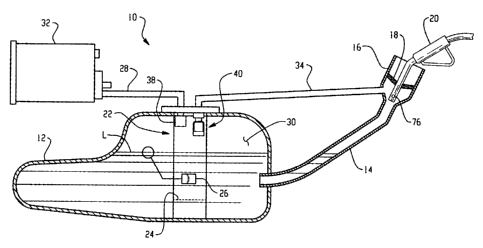
[0006] FIG. 1 is a schematic of a fuel tank vapor control system employing the
valve assembly of the present invention for controlling vapor recirculation to
the
filler tube during refueling; and,
[0007] FIG. 2 is a cross-sectional view of the control valve for recirculation
of
the embodiment of FIG. 1.
DETAILED DESCRIPTION OF THE INVENTION
[0008] Referring to FIG. 1, the fuel tank vapor emission system is indicated
generally at 10 and includes a fuel tank 12 filled with liquid fuel to a level
L and
having a filler tube 14 connected through a wall of the tank. A nozzle
receiving
cup 16 is provided and preferably formed at the upper end of the filler tube
with a
flexible seal 18 disposed therein for sealing about a dispensing nozzle 20
upon
insertion therein.
[0009] The tank 20 includes a fuel pump/level sender module indicated
generally at 22 which has a pump 24 and a level sender 26 immersed in the
fuel.
A vapor storage line 28 communicates through the module with the vapor dome
30 within the tank and above the liquid fuel, which line is connected to a
storage
device 32 which may comprise a canister filled with adsorbent material such as
granulated charcoal. The module 22 has a vapor recirculation line 34 connected
thereto which is also connected to the cup 16 and the upper end of the filler
tube
at a location downstream of the nozzle seal 18.
[0010] A vapor storage line 28 is connected to a float operated valve 38 which
serves to close the line 28 upon the level L of the fuel rising to the full
mark in the
tank. It will be understood that valve 38 also closes in the event of a
vehicle
rollover.
[0011] A second valve assembly indicated generally at 40 is connected to
recirculation line 34 and functions as will hereinafter be described.
[0012] Referring to FIG. 2, the valve assembly 40 includes a two-stage
vacuum or differential pressure operated valve indicated generally at 42 and a
-3-
CA 02472709 2004-06-30
float operated valve indicated generally at 44 preferably mounted in a common
housing 46 with valve 42.
[0013] Float operated valve 44 includes a valve seat 48 formed in the housing
within an enlarged diameter portion 50 and includes a float 52 having a
valuing
surface 54 provided on the upper end thereof for closing against the valve
seat 48
in response to the level L of the fuel in the tank reaching the float 52
through
aperture 53 provided in housing 50. It will be understood valve 44 also closes
in
the event of a vehicle rollover. The float is calibrated by a buoyancy spring
56
provided within the portion 50 of the housing in a manner known in the art.
[0014] The two-stage flow control valve 42 has a fitting 58 which is adapted
to
be connected to the recirculation line 34 (not shown in FIG. 2) with an outlet
passage 60 formed therein communicating with an enlarged diameter chamber
62. A moveable obturator 64 is slidably disposed therein and which has a
valuing
surface 66 formed on the lower end thereof for movement with respect to valve
seat 68 formed in the chamber 62. A reduced diameter or limited flow passage
70 is formed through the obturator 64 and provides for limited or a relatively
low
rate of flow to the outlet passage 60 when the obturator is closed against
valve
seat 68.
[0015] The upper end of the obturator 64 has a piston portion 72 which closely
interfits with bore 74 formed in the chamber 62 for sliding movement therein.
It
will be understood that the piston 72 and the valuing surface 66 are removed
in
response to differential pressure forces acting across the piston 72 such as
those
created by a vacuum being formed in the cup 16.
[0016] In operation, with a typical nozzle 20 having a vacuum shutoff
mechanism therein (not shown), activated by vacuum within the region of cup 16
below the seal 18 acting through a port 76 provided in the nozzle. In the more
common and widely used systems, during refueling the pressure in the cup in
the
space below seal 18 runs at about 0.5 kPa sub-atmospheric depression or
vacuum; and, the more common nozzles are set to shut off when the vacuum is in
the range of about 1.75 to 2.5 kPa. These settings represent a fuel vapor flow
through conduit 34 of about six liters per minute.
-4-
CA 02472709 2004-06-30
[0017] However, in those geographic regions where tighter seal requirements
are required for the nozzle, or where the nozzle includes a bellows or seal
sealing
over the upper end of cup 16, the fuel flow discharging from the nozzle
creates a
greater depression or vacuum within the cup 16. In such systems a vacuum level
of about one kPa differential pressure is created between the space within the
cup 16 and the vapor pressure within the tank dome 30; and this causes
obturator
64 to move upwardly opening valve seat 68 to permit greater flow.
[0018] It will be understood that at vacuum levels below one kPa, obturator 64
is seated against valve seat 68 and flow is through the passage 70.
[0019] It will further be understood that the settings for the opening of
valve 42
may be changed to accommodate different regional nozzle configurations as may
be required.
[0020] The present invention thus provides for controlling the recirculation
of
fuel vapor to a filler tube to prevent creation of a relatively strong vacuum
in the
filler tube and from causing premature shutoff of the vacuum actuated
mechanism
in the dispensing nozzle. The vacuum operated flow control valve for vapor
recirculation of the present invention may conveniently be combined in a
common
housing with a float operated rollover shutoff valve.
(0021] Although the invention has hereinabove been described with respect to
the illustrated embodiments, it will be understood that the invention is
capable of
modification and variation and is limited only by the following claims.
What is claimed is:
-5-