Note: Descriptions are shown in the official language in which they were submitted.
CA 02472941 2004-07-09
WO 03/060407 PCT/US03/01019
APPARATUS AND METHOD FOR CONTROLLING
THE TEMPERATURE OF MANUFACTURING EQUIPMENT
FIELD OF THE INVENTION
The present invention relates to processes and equipment for controlling
and/or adjusting
the temperature of equipment used in the manufacture of a film, web or other
articles that are
typically manufactured in a high speed, continuous manner.
BACKGROUND OF THE INVENTION
During manufacturing processes, and more typically during high speed
manufacturing
processes, rolls and/or belts are often used to guide articles or materials
and/or to perform certain
operations that can affect the properties of the materials or articles being
manufactured. For
example, rolls and/or belts may be used to calender, emboss, heat, cool,
tension, direct, apply
glue, ink or other substances, etc. to materials or articles during
manufacturing or converting
processes. Typically, when rolls or belts are used in conjunction with the
manufacture or
converting of materials or articles in a continuous process, the material or
article is in contact
with the roll throughout only a portion of the roll's rotation or the belt
through only a portion of
its path. For certain operations, it may be desirable for the material or
articles being processed to
reach or maintain a certain temperature range while in contact the roll
through one portion of its
rotation (or in the use of a belt, a portion of its path) and a different
temperature when in contact
with the roll through a different portion of its rotation. Alternatively, it
may be desirable for one
or more of the rolls and/or belts to be heated or cooled to a certain
teinperature range through a
certain portion of its rotation or path and heated or cooled to another
tenlperature range along a
different portion of its rotation or path. However, controlling the
temperature of the material
being processed or the rolls and/or belts themselves can be very complicated
and costly and is
very difficult to achieve with current technology, especially at high speeds.
Current techniques for cooling rolls used during manufacture include passing
fluid
through the roll to control the temperature of the roll, applying air, steam
or water to the
circumference of the roll and contacting an idler roll to the manufacturing
roll to add or remove
heat from the surface of the manufacturing roll. Examples of such methods are
disclosed in U.S.
patents 4,805,554 issued to McIntyre; 5,058,496 issued to Wittkopf; 5,212,975
issued to
Ginzburg; 5,799,411 issued to Scheil and 6,256,903 issued to Rudd. However,
techniques
1
CA 02472941 2007-04-04
focusing on convective cooling has significant significant shortcomings in
that it cannot transfer
heat as efficiently as conduction, thereby limiting production rates. Further,
the use of fugitive
fluid for heating or cooling is often undesireable due to the inherent
recovery and hygiene
difficulties. With respect to the use of a roll contacting another roll to
provide heat exchange,
such methods are relatively inefficient because duration of the heating or
cooling of the
circumference of the roll being heated or cooled is limited by the nip between
the rolls. The
present invention overcomes these disadvantages by providing the capability to
conductively chill
a greater portion of a roll's surface. Furthermore, this invention provides
the capability to
provide supplemental vaccum forces to assist in the removal of the
web/adhesive structure form
the roll's surface coincident with the temperature reduction.
Accordingly, it would be desirable to provide a cost effective method and/or
apparatus
for controlling the surface temperature of a belt as it moves along its path.
It would also be
desirable to provide a cost effective method and/or apparatus for controlling
the surface
temperature of a roll as it rotates about its axis. Further, it would be
desirable to provide an
apparatus and/or method of controlling the temperature of a material and/or
article being
manufactured or converted using a roll or belt, wherein the temperature of the
material and/or
article is controlled while passing through a given portion of the roll's
rotation about its axis or
the belt's movement along its path. Further, it would be desirable to have an
apparatus and/or
method of providing zone temperature control of a roll or belt or a material
being processed in an
operation employing rolls or belts that can be used with or in place of
current roll or belt
technology. It would also be desirable to provide an improved process and
apparatus for
providing zone temperature control of a roll, belt or a material being
processed in an operation
employing rolls or belts that can be employed at high speeds and/or in
continuous operations.
The
citation of any document is not to be construed as an admission that it is
prior art with respect to
the present invention.
SUMMARY OF THE INVENTION
An object of the present invention is to provide an app_aratus and method for
controlling the temperature of manufacturing equipment.
The method and apparatus of the present invention provide a unique solution to
the
problems of the prior art by using a belt to modify the temperature of a
manufacturing roll. For
example, the method and apparatus of the present invention-may be used to zone
control the
2
CA 02472941 2005-06-28
temperature of a rotating roll. In one embodiment, the apparatus may include a
roll having a
surface at a first temperature, the roll capable of rotating about an axis;
and a belt disposed
adjacent at least a portion of the surface of the roll and contacting the
surface of the roll in a
contact region, the belt having a second temperature that is different from
the first temperature,
wherein the belt affects a temperature change in at least a portion of the
surface of the roll in the
contact region as the roll is rotated.
One method for zone controlling the temperature of a rotating roll according
to the
present invention includes the following steps: (a) providing a roll having an
axis and a surface at
a first temperature; (b) providing a belt disposed adjacent at least a portion
of the surface of the
roll; (c) heating or cooling the belt to a second temperature that is
different from the first
temperature; (d) directly or indirectly contacting the belt with the surface
of the roll in a contact
region, (e) rotating the roll while in contact with the belt such that the
belt affects a temperature
change in at least a portion of the surface of the roll in the contact region
as the roll is rotated.
In accordance with another aspect of the invention, there is provided an
apparatus for
aiding the removal of an adhesively coated web from a surface of a rotating
roll at a first
temperature, the apparatus comprising:
a moveable belt disposed about at least a portion of the surface of the roll
defining a
contact region, the belt having a second temperature that is different from
the first
temperature such that as the web passes between the surface of the roll and
the belt,
the adhesively coated web is cooled to third temperature that is different
from the
first temperature.
In accordance with another aspect of the invention, there is provided a method
of
embossing a web, the method comprising the steps of:
(a) providing a first embossing roll having a first embossing pattern disposed
thereon;
(b) providing a second embossing roll that is engaged with the fnst embossing
roll, the
second embossing roll having a second embossing pattern disposed thereon, the
first embossing pattern and the second embossing pattern being complementary;
(c) maintaining the second embossing roll at a first temperature;
(d) applying an adhesive to the second embossing roll;
(e) contacting a web of sheet material with the second embossing roll such
that the
adhesive forms an adhesive pattern on the web of sheet ma.terial in register
with the
second embossing pattern of the second embossing roll;
(f) passing the web of sheet material between the first embossing roll and the
second
embossing roll wherein the first embossing roll and the second embossing roll
3
CA 02472941 2005-06-28
emboss the web with the complementary embossing pattern;
(g) providing a belt disposed about at least a portion of the second embossing
roll, the
belt having a second temperature that is different from the first temperature;
(h) passing the web between the belt and the second embossing roll; and
(e) removing the web of sheet material from the second embossing roll.
In accordance with another aspect of the invention, there is provided a method
of
modifying a web, the method comprising the steps of
(a) providing a first embossing roll having a first embossing pattern disposed
thereon;
(b) providing a second embossing roll that is engaged with the first embossing
roll,
the second embossing roll having a second embossing pattern disposed thereon,
the first embossing pattern and the second embossing pattern being
complementary;
(c) maintaining the second embossing roll at a first temperature;
(d) providing a belt in contact with at least a portion of the surface of the
second
embossing roll, the belt having a second temperature that is higher than the
first
temperature such that the belt heats a region of the surface of the second
embossing roll;
(e) applying an adhesive to the second embossing roll in the region of the
surface of
the second embossing roll heated by the belt;
(f) contacting a web of sheet material with the second embossing roll such
that the
adhesive fonns an adhesive pattern on the web of sheet material in register
with
the second embossing pattem of the second embossing roll;
(g) passing the web of sheet material between the first embossing roll and the
second
embossing roll wherein the first embossing roll and the second embossing roll
emboss the web with the complementary embossing pattern; and
(h) removing the web of sheet material from the second embossing roll.
Alternative methods and apparatuses to perform the methods are contemplated
and
described in more detail in the following sections of this specification.
BRIEF DESCRIPTION OF THE DRAWINGS
While the specification concludes with claims which particularly point out and
distinctly
claim the present invention, it is believed that the present invention will be
better understood
3a
CA 02472941 2005-06-28
from the following description of preferred embodiments, taken in conjunction
with the
accompanying drawings, in which like reference numerals identify identical
elements and
wherein:
FIG. 1 is a schematic illustration of one embodiment of the apparatus
according to the
present invention; and
FIG. 2 is a schematic illustration of an alternative embodiment of the
apparatus according
to the present invention.
FIG. 3 is a schematic illustration of an alternative embodsiment of the
present invention.
FIG. 4 is a schematic illustration of an alternative embodiment of the present
invention.
DETAII,ED DESCRIPTION OF THE INVENTION
The present invention relates to a method and apparatus for controlling and/or
adjusting
the tempera.ture of equipment, such as rolls and/or belts, used in the
manufacture of a filxn, web
or other articles that are typically manufactured in a high speed, continuous
manner. However, it
should be understood that the method and apparatus of the present invention
may also be
3b
CA 02472941 2004-07-09
WO 03/060407 PCT/US03/01019
applicable to non-continuous manufacturing processes and apparatuses that are
used therein as
well as processes and equipment that do not operate at high speeds.
It is well known in the art that during manufacturing processes, and more
typically during
high speed manufacturing processes, rolls (or rollers) and/or belts are often
used to guide articles
or materials and/or to perform certain operations that can affect the
properties of the materials or
articles being manufactured. As used herein, the terms "roll", "rolls",
"roller" or "rollers" refer
to generally cylindrically shaped devices that are configured to rotate about
an axis. Such rolls or
rollers typically provide a surface against which the article or material
being processed will be
directed for at least some period of time. In continuous processes, the
material or article being
processed is generally disposed against the surface of the rolls for only a
portion of the roll's
rotation before the material or article is removed from contact with the
surface of the roll and
directed to another apparatus or processing step. As used herein, the terms
"belt" or "belts" refer
to a continuous band of material configured to move in a predetermined path.
Such belts
typically provide a surface against which the article or material being
processed will be directed
for at least some period of time. In continuous processes, the material or
article being processed
is generally disposed against the surface of the belts for only a portion of
the belt's rotation
before the material or article is removed from contact with the surface of the
belt and directed to
another apparatus or processing step (in order to simplify the disclosure of
the present invention
and to reduce repetition, the following discussion will generally be directed
to the use of rolls for
providing the working surface of the apparatus, however, it should be
understood that belts and
other equipment can be used and that the apparatus and method of the present
invention is
intended to include such altexnatives, without limitation). As noted above,
rolls are used for may
purposed during typical manufacturing processes, including, but not limited to
calendering,
embossing, heating, cooling, tensioning, directing, and applying glue, ink or
other substances to
the materials or articles being processed. For certain operations, it may be
desirable for the
material or articles being processed to reach or maintain a certain
temperature range while in
contact the roll through one portion of its rotation and a different
temperature when in contact
with the roll through a different portion of its rotation. Alternatively, it
may be desirable for one
or more of the rolls to be heated or cooled to a certain temperature range
through a certain portion
of its rotation and heated or cooled to another temperature range along a
different portion of its
rotation. However, providing zone controlled temperature of the material being
processed or the
rolls themselves is very difficult to achieve with conventional technology,
especially at high
speeds. Accordingly, it has been discovered that a relatively inexpensive
apparatus and method
4
CA 02472941 2004-07-09
WO 03/060407 PCT/US03/01019
can be used to provide such zone temperature control for materials and/or
articles that are
processed using one or more rolls.
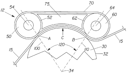
Figure 1 is a schematic illustration of one relatively simple embodiment of
the apparatus
and method according to the present invention. As shown in the figure, web 15
is passed over a
roll, in this case roll 30. In this einbodiment, the web 15 is moving
continuously from the lower
left-hand corner of the figure to the upper right-hand corner of the figure as
it is processed.
In the embodiment shown in Figure 1, the web 15 is contacted with the surface
32 of the
roll 30. (It should be understood that the phrase "in contact" as used herein,
refers to direct or
indirect contact between two surfaces, materials or articles. Thus, a web is
considered in contact
with a roll when directly touching the surface of the roll, as well as when
the web is not directly
touching the surface of the roll, but is touching a material that is in turn
directly touching the roll.
Further, a belt or roll is deemed to be in contact with another belt, roll or
other piece of
equipment if it is in direct contact or if it is in contact with a web or
article which is in turn in
contact with the other piece of equipment.) After the web is placed in contact
with the surface 32
of the roll 30, the web 15 moves with the ro1130 throughout a portion of the
roll's rotation about
its axis 34. Thus, the web 15 is wrapped around a portion of the roll 30
defined by a contact
angle 120. Prior to being removed from the surface 32 of the roll 30, the web
15 is passed
between the roll 30 and a temperature modifying apparatus 12, as shown in
Figure 1.
The temperature modifying apparatus 12, shown in Figure 1, includes a belt 70
that
rotates continuously about rolls 50 and 60 having surfaces 52 and 62 and axes
54 and 64,
respectively. The temperature modifying apparatus 12 is preferably positioned
adjacent the
surface of a roll, such the surface 32 of roll 30, used in the manufacture,
converting or other
processing of a particular material or article. Preferably, the rolls 50 and
60 of the temperature
modifying apparatus 12 are disposed such that the belt 70 is in contact with
the working surface
32 of the manufacturing roll 30 for at least a portion of the circumference of
the manufacturing
roll's 30 surface 32. As shown in Figure 1, the belt contact region C is
located between the point
A at which the belt 70 first contacts the roll 30 and the point B at which the
belt 701ast contacts
the roll 30 during normal operation of the apparatus. The contact region C can
also be described
in terms of the angle between a pair of lines 100 and 110 extending radially
from the axis 34 of
the manufacturing roll 30 through the points A and B, respectively. One
benefit of the apparatus
of the present invention is that the contact region C can be greater than a
typical nip between two
contacting rolls. In certain embodiments, it may be preferred that the contact
region C be at least
about 5 degrees of the surface of the roll 32. In other einbodiments, the
contact region C may be
CA 02472941 2004-07-09
WO 03/060407 PCT/US03/01019
at least about 10 degrees of the surface of the roll 32 or may be at least
about 15 degrees of the
surface of the roll 32. Accordingly, the use of a belt 70 in the temperature
modifying apparatus
12 of the present invention may provide for more effective and/or efficient
heat transfer as
opposed to simply contacting two rolls of different temperatures.
The contact angle 120, and thus, the contact region C, can be increased or
decreased by
moving the belt 70 toward or away from the axis 34 of the manufacturing roll
30. Alternatively,
the contact angle 120 can be increased or decreased by adjusting the distance
between the rolls
50 and 60 that hold the belt 70 against the surface 32 of the manufacturing
roll 30. This type of
adjustment is one useful way to increase or decrease the amount of temperature
adjustment that
can be made using the apparatus 12 of the present invention. These and other
adjustment means
could be especially useful at start up of the machine to compensate for
temperature changes as
temperatures are reaching equilibrium. The adjustment may also be useful to
coinpensate for
intentional changes in line speed.
As the web 15 passes between the manufacturing roll 30 and the belt 70, the
belt 70 can
heat or cool the web 15 and/or the surface 32 of the manufacturing roll 30.
For example, if the
manufacturing roll 30 is running at ambient temperature, the belt 70 can be
heated above the
ambient temperature or cooled to a temperature below the ambient temperature
such that as the
belt 70 passes through the contact region C, the belt 70 heats or cools the
web 15 and/or the
surface 32 of the manufacturing roll 30. In other embodiments, the
manufacturing roll 30 may be
heated or cooled to provide a temperature differential between the belt 70 and
the roll 30. In
certain embodiments, it may be preferred that the difference between the
temperature of the belt
and the temperature of the surface of the roll 30 be at least about 50 F
(about 28 C) or greater
than about 60 F (about 34 C), although other temperature differences may be
desirable for
different uses. In any case, the method and apparatus of the present invention
provide an
effective means for controlling the temperature of a particular region of the
surface of a
manufacturing roll 30 or a material that is placed in contact with such a roll
during processing.
The belt 70 can be of any size, style and can be made of any suitable
materials for the
desired processing step in which the belt is utilized. In certain preferred
embodiments, the belt
70 may be made from metal, rubber, polymeric resins (e.g. Nylon) or a
combination of materials.
Metal belts may be desirable due to their strength and heat capacity. Suitable
metals for use in
the belt considering heat properties and cost are, for example, steel
(generally having a heat
capacity or specific heat of about 0.12 cal/gn1 C), Aluminum (generally
having a heat capacity
of about 0.2 cal/gm oC), stainless steel (generally having a heat capacity of
about 0.103 cal/gm
6
CA 02472941 2004-07-09
WO 03/060407 PCT/US03/01019
C), and alloys of these and other metals or combinations thereof (generally
having a heat
capacity in the range of about 0.10 to about 0.23 caUgm C). Alternatively,
the belt may be made
from a polymer that is reinforced with and/or filled with high heat capacity
materials. Suitable
high heat capacity low cost mineral fillers may include, for example, alumina
(having a heat
capacity of about 0.2 cal/gm C), limestone (having a heat capacity of about
0.217 cal/gm C),
silica (having a heat capacity of about 0.316 cal/gm C), gypsum (having a
heat capacity of about
0.259 cal/gin C), and most metals or metal oxides in powder or filament form
or combinations
thereof. In certain preferred embodiments, where the belt includes a filler
material, the filler may
have a heat capacity or specific heat of at least about 0.09 cal/gm C. In
other embodiments, the
heat capacity of the filler may be at least about 0.15 cal/gm C or at least
about 0.20 cal/gm C.
The belt 70 can be impermeable or permeable of have regions of differing
permeability.
One advantage of a permeable or semi-permeable belt is that air, water or
other fluids can be
passed through the belt 70 as a means to transfer heat to or from the belt 70.
Further, a permeable
belt can provide openings through which a vacuum can be provided to help
remove the material
or article being manufactured from the manufacturing roll 30. Perforated metal
belts and metal
screens are generally suitable for use with the present invention. An
advantage of metal screens
is that they can be configured to have different strands made of different
materials. Thus, for
example, it may be desirable to provide relatively strong strands in the
machine direction and
relatively high heat capacity strands in the cross machine direction, or vice
versa.
The belt 70 can be generally flat or may have some structure. The belt 70 may
also be
used to provide some properties to the article or web being manufactured, such
as a three-
dimensional structure, or may be used to add or remove materials fiom the web
(e.g. printing,
adding adhesive, etc.). Further, the belt 70 may be of any suitable width.
Accordingly, the belt
70 can be the same width as the manufacturing roll 30 or the web 15, or can be
larger or smaller
than either. If the belt 70 is smaller in width than the web 15 or
manufacturing roll 30, the
heating or cooling effects of the belt 70 can be directed to only a portion of
web 15 or roll, if so
desired. Alternatively, only a portion of the belt 70 may be heated or cooled
to give a similar
effect. In yet another embodiment, two or more belts may be used and can be
spaced apart and/or
made from different materials. In any case, such embodiments may provide for
zone heating or
cooling of the roll 30 or web 15 in the cross-machine direction.
Alternatively, for machine
directional control of heating or cooling, the belt 70 may be intermittently
heated or cooled or
may be made from materials that produce or retain different amounts of heat
energy. Thus,
7
CA 02472941 2004-07-09
WO 03/060407 PCT/US03/01019
intermittent or continuous patterns of heating or cooling can be achieved in
both the machine and
cross-machine directions, if desired.
The rolls, including the manufacturing rolls 20, 30 and 40, as well as the
belt rolls 50 and
60 can be of any size and be made of any suitable material. In many lrnown
processes, for
example, in the manufacture of paper products, films and nonwoven materials,
rolls are often
made of metal to prolong their life. However, the rolls may be made from or
coatede with
materials such as rubber, synthetic rubber, polymers, plastic, wood, ceramics,
glass or any other
material suitable for the particular use desired. Further, all or a portion of
the surface of any of
the rolls may be covered or coated with materials that alter or otherwise
provide some benefit to
the roll for its intended use. For example, steel rolls are often coated with
Teflon, silicone,
rubber, synthetic rubber or other polymers to alter the characteristics of the
surface of the roll.
The roll or rolls may be solid or hollow and may be rotated by any lrnown
means,
including, but not limited to electric motors, belts, gears, etc. In certain
embodiments, the roll or
rolls are not actively rotated by a source dedicated to the rotation of the
rolls, but are rotated due
to contact with other rolls that are rotating or belts that are in contact
with a portion of the roll's
surface. In other embodiments, the material or article being processed
provides the means for
rotating one or more of the rolls. Any of the rolls can be heated or cooled
internally or externally
and the surface of the rolls can talce on any desired configuration. In some
embodiments, the
surface of the rolls may be smooth, while in other einbodiments, the surface
of at least some of
the rolls may have raised or depressed regions. The surface of the rolls may
be continuous or
may include any number of openings or passages in their surface or body for
any desired purpose.
Thus, for example, the surface of a roll may be entirely or partially screen-
like, having a number
of openings through which air can pass. In yet other embodiinents, the cross-
section of the roll
may not be circular, but may take on any suitable shape such as an oval, an
octagon or an
irregular shape including any number of curves or linear portions.
The temperature modifying apparatus 12 may also include a means or device for
controlling the temperature of the belt 70. The belt temperature control
device can use any
known means for heating or cooling a surface or structure, including, but not
limited to heat
exchangers or other heating or coding devices that use hot or cool air,
radiant heating, friction,
evaporation, light, magnetism, radio waves, microwaves, laser light,
refrigeration, or any
combination of these and other heating and cooling methods. In one embodiment,
the rolls 50
and/or 60 may be cooled or heated to cool or heat the belt 70. In another
embodiment, as shown
in Figure 1, the temperature modifying apparatus 12 may include a vacuum
plenum 75. The
8
CA 02472941 2004-07-09
WO 03/060407 PCT/US03/01019
vacuum plenum 75 pulls air across the belt 70 to cool or heat the belt 70 as
it rotates. In other
embodiments, the vacuuin plenum 75 may include a heating element or a cooling
element to
further heat or cool the air before it passes over the belt 70. Further, when
the belt is permeable
to air, the vacuum may pull air through some or all of the openings in the
belt. This may provide
for more rapid and/or even heating or cooling of the belt 70.
The temperature modifying apparatus 12 may also be useful to help remove the
web 15
from the roll 30 without distorting the web 15 or otherwise negatively
impacting the structure of
the web 15. For example, if the teinperature modifying apparatus 12 includes
an air pervious belt
and a vacuum, the apparatus may be configured such that the vacuum pulls the
web 15 from the
rol130. This may provide for a more gentle removal of the web 15 from the roll
30. (Although
not wishing to be bound by theory, it is believed that the vacuum can provide
for better removal
because it spreads the forces over a larger area of the web and thus, reduces
localized stress
concentrations. Further, a removal force generally perpendicular to the
machine direction and the
plane of the web can help reduce the machine direction forces otherwise needed
to strip the web
from the roll.) This can be useful when the web 15 is glued or otherwise stuck
to or has a
tendency to stick to the roll 30, especially if the removal force is provided
at the time when the
adhesive is cooled or heated to be less tacky. Further, cooling of the web 15
may increase its
strength and allow for more aggressive removal operations. Other means for
improving removal
of the web 15 from the roll 30 may include static electricity or coatings or
materials that provide
some affinity between the belt 70 and the web 15. In any case, it may be
desirable to remove the
web 15 from the roll, while the web 15 is still in contact with the belt 70.
Otherwise, the cooling
or other characteristics of the belt 70 may be lost as the web 15 continues to
be disposed adjacent
the surface of the roll beyond the contact region C.
Although the temperature modifying apparatus 12 of the present invention has
been
described in tenns of a device including a belt rotating continuously about at
least two rolls, the
apparatus can be modified to include different elements, if desired. For
example, the apparatus
12 may include non-rotating bars in addition to or in place of one or more of
the rolls 50 and 60.
The bars can be used to direct and/or tension the belt 70. Further, the
apparatus 12 may include a
belt support to help keep the belt 70 from sagging and/or to help direct
and/or adjust the belt 70
against a surface, such as the surface 32 of the manufacturing roll 30. The
apparatus 12 of the
present invention could also be provided with belt tensioning and/or belt
tracking systems, as
desired for a particular operation. In yet other embodiments of the present
invention, the
temperature modifying apparatus 12 may be used to heat or cool the surface of
manufacturing
9
CA 02472941 2007-04-04
equipment other than rolls, such as, for example, planar and curved moving and
non-moving
surfaces, belts, shafts and the like.
Figure 3 depicts an alternative embodiment of the present invention wherein
the
temperature modification apparatus 112 includes a belt 170 that is disposed
adjacent at least a
portion of manufacturing belt 130. Web 115 is shown to pass between the belt
170 and the
manufacturing belt 130, however, embodiments are contemplated wherein the
material or article
being manufactured or converted does not pass between the temperature
modifying apparatus 112
and the manufacturing belt 130. In any case, as in the other embodiments
described herein, the
belt 170 of the temperature modifying apparatus 112 preferably heats or cools
at least a portion of
the surface 132 of the manufacturing belt 130, typically in contact region Cl
located between the
point Al where the belt 170 first touches the manufacturing belt 130 during
normal operation and
point B 1 where the belt 170 last touches the manufacturing belt 130. The
temperature modifying
apparatus 112 may also include means for facilitation the removal of the web
115 from the
surface 132 of the manufacturing belt 130 such as those described herein with
respect to other
embodiments of the present invention.
Exemplary Embodiment
In one exemplary embodiinent, the method and apparatus of the present
invention may be
used during the manufacture of a sheet material that includes a thin layer of
pressure-sensitive
adhesive in certain predetermined locations, such as the food and storage
wraps described in
detail in commonly-assigned patents, namely, Hamilton et al., U.S. Patent No.
5,662,758, entitled
"Composite Material Releasably Sealable to a Target Surface When Pressed
Thereagainst and
Method of Making", Hamilton et al., U.S. Patent No. 5,871,607, entitled
"Material Having A
Substance Protected by Deformable Standoffs and Metliod of Making", McGuire et
al., U.S.
Patent No. 5,965,235, entitled "Three-Dimensional, Nesting-Resistant Sheet
Materials and
Method and Apparatus for Making Same", and Hamilton et al., U.S. Patent No.
6,194,062,
entitled "Improved Storage Wrap Materials", and McGuire et al., U.S. Patent
No. 6,193,918,
entitled "High Speed Embossing and Adhesive Printing Process and Apparatus"
For such applications, it has been found to be advantageous to include the
temperature
modifying apparatus 12 of the present invention to help increase the speed and
reliability of the
process. Specifically, as described in more detail below, adhesive is applied
to a film by means
CA 02472941 2004-07-09
WO 03/060407 PCT/US03/01019
of a roll. The method and apparatus of the present invention can be employed
to help cool,
solidify and/or deactivate the adhesive such that the adhesive coated film can
be more easily
removed from the adhesive application roll.
FIG. 2 illustrates in schematic form, a high speed embossing process and high
speed
embossing apparatus 10 including the temperature modifying apparatus 12 of the
present
invention. (Although this example is described in terms of an embossed web,
the present
invention is equally applicable to non-embossed webs.) The high speed
embossing apparatus 10
comprises first and second embossing rolls 20 and 30. The first and second
embossing rolls 20
and 30 have a complementary (i.e., matched) embossing pattern which interlocks
to emboss the
pattern onto a web 15 of material passed therebetween. The embossing roll
provided with
pockets and raised lands is generally referred to as the female embossing
roll. The embossing
roll with raised nubs and recessed lands is generally referred to as the male
embossing roll. It
will be understood that either the first or second embossing roll 20 and 30
can be the male or
female roll. As a non-limiting example, if the first embossing roll 20 is
determined to be the
female roll, then the second embossing roll 30 should be the male roll. It may
be preferred that
one of the embossing rolls have a release material, such as a silicone-based
or a fluorocarbon-
based material (i.e. FEP), disposed thereon. The release material generally
has a high release
characteristic to facilitate removal of the embossed final product from the
embossing roll.
As shown in FIG. 2, the high speed embossing apparatus 10 may further include
an
adhesive application ro1140 (having axis 44) that supplies a metered amount of
adhesive 46 to the
second embossing roll 30 from an adhesive supply. The surface 42 of the
adhesive application
roll 40 is preferably conformable to the surface 32 of the second embossing
roll 30.
Alternatively, the surface 32 of the second embossing roll 30 may be
conformable to the surface
42 of the adhesive application ro1140. This helps ensure that the entire
surface of the embossing
roll 30 is coated with the adhesive 46. More specifically, with reference to
FIG. 2, an adhesive
46 is extruded onto the surface 42 of the adhesive application roll 40 via a
slot die 48. However,
it would be known to one of skill in the art that other methods to supply an
adhesive 40 to the
adhesive application ro1140 can be used. Once the adhesive is applied to the
adhesive application
ro1140, it is transferred by contact to the surface 32 of the second embossing
ro1130.
In one preferred embodiment, adhesive 46 is applied only to the land areas of
the second
embossing rbll 30. This can be accomplished by carefully controlling the
interaction between
second embossing roll 30 and the adhesive application ro1140 so that the
adhesive application roll
40 does not press the adhesive 46 into the recesses around or pockets between
the lands of second
11
CA 02472941 2004-07-09
WO 03/060407 PCT/US03/01019
embossing roll 30. For this reason, it may be desirable for the second
embossing roll 30 and the
adhesive application roll 40 to have matched surface speeds. Deposition of
adhesive 40
exclusively onto the lands of the second embossing roll 30 prevents adhesive
40 from being
transferred onto the non-recessed regions of the einbossments in the finished
embossed adhesive
coated web 15.
For exemplary purposes only, adhesive application roll 40 can be a rubber
coated steel
roll. The nip between adhesive application roll 40 and the second embossing
roll 30 may be
controlled in the machine direction with precision wedge blocks. It is
believed that a rubber
coating can be utilized to both protect the coating on the second embossing
roll 30 from damage
and also allow the adhesive application roll 40 to be very lightly pressed
against the second
enibossing roll 30 so the deflection of the rubber compensates for the actual
runout of the second
embossing roll 30 and the adhesive application rol140. Alternatively, the
second embossing roll
30 may exhibit conformable characteristics and the adhesive application roll
40 may exhibit non-
conformable characteristics. This can help the adhesive 40 to be applied
evenly on the lands of
second embossing roll 30. However, it would be known to one of skill in the
art that either the
second embossing roll 30 or the adhesive application roll 40 can be any
arrangement of
conformable/non-conformable as long as the adhesive 46 is provided in a
topically efficacious
manner.
As shown in Figure 2, web 15 is directed into contact with the surface 22 of
the first
embossing roll 20 (having axis 24). Alternatively, web 15 is directed into
contact with the
surface 32 of the first embossing ro1130 (having axis 34). The web 15 is then
embossed between
the nip of the first embossing ro1120 and the second embossing roll 30, shown
in Figure 2 as nip
E. The embossed web 15 is adhered to the surface 32 of the second embossing
ro1130 as the roll
30 rotates from the nip E to the contact region C. The surface 32 of the
second embossing ro1130
preferably has release characteristics. That is, it is configured or treated
to allow the adhesive 46
to stick to the web 15 and not the surface of the ro1130 when the web 15 is
removed from the roll
30. The release characteristics and the adhesive properties should be
carefully balanced to
provide the best combination of adhesion and release.. An exemplary release
characteristic would
be a coating which allows a hot (typically about 250-350 F (121-177 C))
adhesive to transfer to
the second embossing roll 30 and yet allows the embossed adhesive coated web
15 to release
from the second embossing roll 30 at a lower temperature. If the release
characteristic promotes
too little adhesion, the adhesive will not transfer from the adhesive
application roll 40 to the
second embossing roll 30. However, if the release characteristic promotes too
much adhesion,
12
CA 02472941 2004-07-09
WO 03/060407 PCT/US03/01019
the final adhesive coated web 15 may not be able to be removed from the
surface 32 of the
second embossing roll 30 without tearing, stretching or otherwise deforming
the web of sheet
material 15.
In one exemplary embodiment, in order to improve adhesive transfer from the
adhesive
application roll 40 to the second einbossing roll 30, the surface 32 of the
embossing roll 30 is
heated. The surface may be heated to any desired temperature, but it has been
found that for the
embodiment described herein, a temperature of between about 250 F and about
350 F (about
121 C to about 177 C) works well. Any type of heater known to those of skill
in the art can be
used to heat the embossing roll 30, including heaters that produce heat by
means of radiation,
conduction, convection and combinations thereof In one embodiment, as is
described in more
detail below, a temperature modifying apparatus 12 of the type described
herein may be used to
heat the surface 32 of the roll. Once the adhesive 46 is applied to the web
15, the interface
between the adhesive 46 and the second embossing roll 30 is preferably cooled
by the
temperature modifying apparatus 12 of the present invention to allow for
easier and inore
effective removal of the adhesively coated web 15 from the roll 30. Thus, in a
preferred
embodiment, the temperature of the interface between the web 15 and the
surface 32 of second
embossing roll 30 is lower in the region where the belt 70 contacts the second
embossing ro1130
than the temperature of the interface between the adhesive 46 and the surface
32 of second
embossing roll 30 at the glue transfer nip G. In sum, a temperature
differential should exist
between the point of adhesive pick-up, glue transfer nip G, and the point
where the embossed
adhesive coated web 15 is removed from the second embossing roll 30. In one
preferred
einbodiment, it has been found that it is preferable that the interface
between the web 15 and the
surface 32 of the roll 30 in the contact region C be less than about 180 F
(about 82 C), more
preferably less than about 140 F (about 60 C) or less than about 100 F (about
38 C). In other
embodiments, it may be desirable to get the temperature of the web 15 to be
within a certain
range in the contact region C. For example, it may be desirable for the
temperature of the web 15
to be less than about 100 F (about 38 C) by the time the web 15 is removed
from the roll.
However, the exact temperature of the web 15 and/or the exact temperature at
each of the regions
and the desired temperature differential will vary depending on the adhesive
and/or film used.
In one alternative embodinient, as shown in Figure 4, a temperature modifying
apparatus
12A of the type described herein can be located adjacent the second embossing
roll 30 between
the point B where the web 15 is removed from the roll 30 and point G where the
glue is applied
to the second embossing roll 30. The belt 70A of the apparatus 12A can be
heated to a
13
CA 02472941 2004-07-09
WO 03/060407 PCT/US03/01019
temperature above the temperature of the surface 32 of the roll 30 such that
the belt 70 heats the
surface 32 of the roll 30 to a temperature suitable for the adhesive 46 to
transfer from the
adhesive application roll 40 to the second embossing roll 32. In such
embodiments, it may be
desirable to cool the second embossing ro1130 internally, by means of the
temperature modifying
apparatus 12 of the present invention or by any other cooling means or
combination of cooling
means to failitate removeal of the adhesively coated web 15 from the second
embossing ro1130 at
point B.
While particular embodiments and/or individual features of the present
invention
have been illustrated and described, it would be obvious to those skilled in
the art that
various other changes and modifications can be made without departing from the
spirit
and scope of the invention. Further, it should be apparent that all
coinbinations of such
embodiments and features are possible and can result in preferred executions
of the
invention. Therefore, the appended claims are intended to cover all such
changes and
modifications that are within the scope of this invention.
14