Some of the information on this Web page has been provided by external sources. The Government of Canada is not responsible for the accuracy, reliability or currency of the information supplied by external sources. Users wishing to rely upon this information should consult directly with the source of the information. Content provided by external sources is not subject to official languages, privacy and accessibility requirements.
Any discrepancies in the text and image of the Claims and Abstract are due to differing posting times. Text of the Claims and Abstract are posted:
| (12) Patent: | (11) CA 2473217 |
|---|---|
| (54) English Title: | EXPANDING TUBING WITH A RADIALLY EXTENDABLE EXPANDER AND CONE |
| (54) French Title: | COLONNE DE PRODUCTION AVEC DISPOSITIF A DEPORT RADIAL ET CONE EXTENSIBLES |
| Status: | Deemed expired |
| (51) International Patent Classification (IPC): |
|
|---|---|
| (72) Inventors : |
|
| (73) Owners : |
|
| (71) Applicants : |
|
| (74) Agent: | MARKS & CLERK |
| (74) Associate agent: | |
| (45) Issued: | 2008-02-05 |
| (22) Filed Date: | 2004-07-08 |
| (41) Open to Public Inspection: | 2005-01-09 |
| Examination requested: | 2004-07-08 |
| Availability of licence: | N/A |
| (25) Language of filing: | English |
| Patent Cooperation Treaty (PCT): | No |
|---|
| (30) Application Priority Data: | ||||||
|---|---|---|---|---|---|---|
|
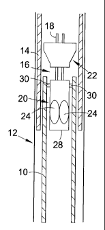
This invention relates to expanding tubing, and in particular to expansion of tubing downhole. Embodiments of the invention relate to anchoring and expanding tubing downhole. In one embodiment, a method of expanding tubing such as a section of casing (10) is disclosed, the method comprising the steps of locating the casing (10) in a bore (12), expanding a portion of the casing (10) to engage the bore wall using an expansion tool (16) having at least one radially movable expansion member, in the form of a roller (24) of a rotary expander (20), and then expanding a further portion of the casing (10) by advancing a cone expander (22) through the casing (10).
La présente invention concerne le déport d'une colonne de production et en particulier le déport d'un fond de trou de la colonne de production. Certains modes de réalisation de l'invention se rapportent à l'ancrage et au déport du fond de trou de la colonne de production. Dans un mode de réalisation, une méthode de déport de colonne de production telle qu'une section de tubage (10) est décrite, la méthode comprenant les étapes consistant à localiser le tubage (10) dans un trou (12), le déport d'une partie du tubage (10) pour engager la paroi du trou à l'aide d'un outil de déport (16) ayant au moins un élément de déport mobile radialement, ayant la forme d'un rouleau (24) d'un dispositif à déport rotatif (20), puis en déportant une autre partie du tubage (10) en faisant avancer un dispositif à déport de cône (22) à travers du tubage (10).
Note: Claims are shown in the official language in which they were submitted.
Note: Descriptions are shown in the official language in which they were submitted.
For a clearer understanding of the status of the application/patent presented on this page, the site Disclaimer , as well as the definitions for Patent , Administrative Status , Maintenance Fee and Payment History should be consulted.
| Title | Date |
|---|---|
| Forecasted Issue Date | 2008-02-05 |
| (22) Filed | 2004-07-08 |
| Examination Requested | 2004-07-08 |
| (41) Open to Public Inspection | 2005-01-09 |
| (45) Issued | 2008-02-05 |
| Deemed Expired | 2018-07-09 |
There is no abandonment history.
| Fee Type | Anniversary Year | Due Date | Amount Paid | Paid Date |
|---|---|---|---|---|
| Request for Examination | $800.00 | 2004-07-08 | ||
| Application Fee | $400.00 | 2004-07-08 | ||
| Registration of a document - section 124 | $100.00 | 2004-09-22 | ||
| Maintenance Fee - Application - New Act | 2 | 2006-07-10 | $100.00 | 2006-06-13 |
| Maintenance Fee - Application - New Act | 3 | 2007-07-09 | $100.00 | 2007-06-12 |
| Final Fee | $300.00 | 2007-08-31 | ||
| Maintenance Fee - Patent - New Act | 4 | 2008-07-08 | $100.00 | 2008-06-10 |
| Maintenance Fee - Patent - New Act | 5 | 2009-07-08 | $200.00 | 2009-06-19 |
| Maintenance Fee - Patent - New Act | 6 | 2010-07-08 | $200.00 | 2010-06-17 |
| Maintenance Fee - Patent - New Act | 7 | 2011-07-08 | $200.00 | 2011-06-08 |
| Maintenance Fee - Patent - New Act | 8 | 2012-07-09 | $200.00 | 2012-06-14 |
| Maintenance Fee - Patent - New Act | 9 | 2013-07-08 | $200.00 | 2013-06-12 |
| Maintenance Fee - Patent - New Act | 10 | 2014-07-08 | $250.00 | 2014-06-19 |
| Registration of a document - section 124 | $100.00 | 2014-12-03 | ||
| Maintenance Fee - Patent - New Act | 11 | 2015-07-08 | $250.00 | 2015-06-17 |
| Maintenance Fee - Patent - New Act | 12 | 2016-07-08 | $250.00 | 2016-06-15 |
Note: Records showing the ownership history in alphabetical order.
| Current Owners on Record |
|---|
| WEATHERFORD TECHNOLOGY HOLDINGS, LLC |
| Past Owners on Record |
|---|
| HILLIS, DAVID JOHN |
| WEATHERFORD/LAMB, INC. |

