Note: Descriptions are shown in the official language in which they were submitted.
CA 02473322 2004-07-14
7
Device for raising or cultivating cells
in a container-like receptacle
The invention relates to a device for raising or cultivating
cells in 2, container-like receptacle which comprises a base
and at least one lid.
For laboratory requirements, it is known to raise ox culti-
vate cell cultures in a shallow receptacle or dish, the cells
simply being placed in the receptacle and culture medium be-
ing added. A lid is then placed on the receptacle.
A disadvantage is that this method can only be used for small
quantities. In particular, the known system is not suitable
for cultivating or raising cells in batches. Moreover, it is
impossible to achieve in vivo conditions, and sterility is
not guaranteed.
An alternative to this was to use a closed system which com-
prised a receptacle with a lid or closure piece and which
permitted sterility. However, a disadvantage of this was that
removing the cell culture was very laborious and time-
consuming.
It is therefore an object of the present invention to improve
a device of the type mentioned at the outset in such a way
that it can be used in a highly versatile manner for raising
or cultivating cells, particularly in large-scale operations,
the aim being to achieve as far as possible ~n vivo condi-
tions and sterility. Moreover, after they have been culti-
vated, the cell cultures should be able to be removed from
the receptacle without great effort and without being dam-
CA 02473322 2004-07-14
2
aged.
According to the invention, this object is achieved by the
features in the characterizing part of claim 1.
In the device according to the invention, the cells in the
receptacle are no longer "left to themselves", and instead an
active process takes place in practice. On the one hand, cuJ.-
ture medium can be introduced continuously ox intermittently,
and, on the other hand, it is possible for the cell cultures
farming to be acted upon with pressure. This pressure actua-
tion can even be effected with alternating pressure in order
to simulate natural conditions as far as possible.
The cells can be raised or cultivated as sEparate cell cul-
tures. In the same way they can also be formed on structures
in order to produce implants.
In the receptacle according to the invention, the cells can
in this way also be exposed to shearing forces or pressure
forces. With the device according to the invention, a wide
variety of cell cultures can be raised or cultivated in a
highly versatile manner.
The receptacle itself can also be provided for this purpose
variously with one or two lids. Likewise, a common connector
bore can be provided for the introduction of culture medium
and for its return. Of course, separate connector bores are
also possible, in which case parallel flows ox through-flows
are possible depending on the arrangement of the connector
bores.
CA 02473322 2004-07-14
3
gy virtue of the configuration according to the invention
with one or two lids or a lid and base, and between them a
receptacle which can simply be a cylinder open at the top and
bottom, the cell cultures can easily be removed from the re-
ceptacle, after they have been treated or raised, without
great effort and without damaging them.
Since according to the invention the cells are raised or cul-
tivated on the lower lid or base or also under the upper lid,
e.g. on a frame connected to the upper lid, the cell cultures
can be easily removed from the receptacle once they are
ready. In any event, good accessibility is afforded by the
removable lids or base.
For pressurization, the receptacle, e.g. the circumferential
wall of the cylindrical receptacle, can also be made elastic.
The connector bore or connector bores can be arranged in one
lid or, if two lids are present, in both lids. Likewise, it
is also possible to form the connector bores in the cylindri-
cal middle part. The number and arrangement of the connector
bores depends on the application and on the cells which are
to be raised or cultivated.
For a tight connection between the lid or lids and the recep-
tacle, clamp connections, sealing rings or threaded connec-
tions with internal and external threads can be provided.
Very good sealing conditions and thus pressure conditions are
obtained if the lid or lids are provided with extension rings
which then sealingly enclose the cylindrical middle part of
the receptacle from the outside.
CA 02473322 2004-07-14
4
If the device according to the invention is to be subjected
to a rolling or turning movement, tensioning rings can be
fitted laterally onto the device, which tensioning rings grip
the lid or lids and the receptacle, and a turning or rolling
means can then be applied to them.
A wide variety of pressurizing means can be used to subject
the interior of the receptacle forming the cell culture cham-
ber to pressure. Suitable for this purpose area for example,
cylinder/piston units which can also operate in pulsed mode
for alternating pressure loads.
If necessary, the receptacle can also be designed as a two-
chamber system so that two different cells or two identical
cells can be cultivated ox raised separate from one another.
In this case, it is advantageous if the lid of the receptacle
is provided with a suspension means on which a platform for
receiving cells is arranged. In this way, one cell type is
raised on the platform, while another cell type can be culti-
vated on the base of the receptacle.
If necessary, the receptacle ox the cylindrical circumferen-
tial wall of the receptacle can be made porous or gas-
permeable, so that in this way too culture medium and/or a
gaseous medium, for example air or oxygen, can be delivered
from this side.
Advantageous developments and configurations will be evident
from the remaining dependent claims and from the illustrative
embodiments described below with reference to the drawing, in
CA 02473322 2004-07-14
which:
Fig. 1 shows a cross section through a first embodiment of a
device with a receptacle and a lid;
Fig. 2 shows a cross section through a device with a cylin-
drical middle part and an upper lid arid lower lid;
Fig. 3 shows a similar configuration to the one in Fig. 2,
with an inlet connector and an outlet connector being
arranged in the upper lid;
Fig. 4 shows a further embodiment of the device according to
the inveriti.on;
Fig. 5 shows a device according to the invention with an up-
per lid and a lower lid, each with external thread,
and a cylindrical middle part with internal thread;
Fig. 6 shows an embodiment with extension rings on an upper
lid and a lower lid;
Fig. 7 shows a similar configuration to the one in Fig. 6,
with a clamp connection;
Fig. 8 shows a similar configuration to the one in Figures 6
and 7, with threaded connections;
Fig. 9 shows an embodiment with two lateral tensioning
rings;
Fig. 10 shows an embodiment similar to the embodiment in Fig.
CA 02473322 2004-07-14
6
9, with a pressurizing means;
Fig. 11 shows an embodiment with a suspension means in the
upper lid, with a cylindrical middle part and a lower
lid;
Fig. 12 shows a similar configuration to the one in Fig_ 11,
in somewhat simpler form with just an upper lid;
Fig. 13 shows a configuration with a pressure force generated
by magnetic forces;
Figures 13a, 13b and 13c show different pressure disk pro-
files;
Fig. 13d shows a mineral matrix for bone replacement as sup-
port structure with two pressure disks;
Fig. 14 shows a configuration with expandable elements for
generating pressure forces;
Fig. 15 shows a configuration with hydraulic or pneumatic
elements for generating pressure forces;
Fig. 16 shows a similar configuration to the one in Fig. 15;
Fig. 17 shows a further configuration similar to those in
Figures 15 and 16;
Fig. 18 shows a configuration with a gas-permeable membrane
as base;
CA 02473322 2004-07-14
7
Fig. 19 shows a configuration with a three-chamber system;
Fig. 20 shows a similar configuration to the one in Fig. 19.
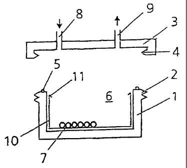
According to the illustrative embodiment in Fig. 1, which
shows the basic configuration of the device according to the
invention, a receptacle 1 is provided which has an external
thread 2. A lid 3 with an internal thread ~ is screwed onto
the receptacle 1, and a sealing ring S forms a pressure-tight
closure of a cell culture chamber 6 for cells 7 provided in
the interior of the receptacle 1.
The lid 3 is provided with an inlet connector bore 8 and an
outlet connector bore 9 in order to introduce culture medium
and if appropriate also oxygen into the cell culture chamber
6 via corresponding lines or tubes.
For easier handling, a tray 10 can be inserted into the re-
ceptacle 1 so as to make it easier to insert and remove the
cells ? which are to be cultivated or raised. For this pur-
pose, beads, flanges 11 or the like which are provided in the
upper area of the tray 10 can also serve for easier removal
and easier insertion. The tray 10 shown only in Fig. 1 can of
course also be provided n the same way or in a similar way in
the other illustrative embodiments.
Fig. 2 shows a configuration where the receptacle 1 forms a
cylindrical middle part which can be closed with the upper
lid 3 in the same way as in the illustrative embodiment ac-
cording to Fig. 1. Provided on the underside there is a fur-
ther, lower lid 12 which forms the base of the receptacle and
which likewise has an internal thread 4 which interacts with
CA 02473322 2004-07-14
8
the external thread 2 of the middle part, said middle part in
this case being provided with two external threads 2, unless
one continuous thread is present. As will also be apparent
from Fig. 2, inlet and outlet connector bores 8 and 9 are
provided in both lids 3 and 12.
Fig. 3 shows a similar configuration to the one in Fig. 2,
with an inlet connector bore 8 and an outlet connector bore 9
being arranged only in the upper lid 3. In the same way as in
the illustrative embodiment according to Fig. 2, sealing
rings 5 are provided on both ends of the cylindrical middle
part of the receptacle 1.
Fig. 4 shows an embodiment in which the cylindrical middle
part as receptacle 1 is provided with an internal thread 2'
which cooperates with an external thread 4' of the upper lid
3 and of the lower lid 12. Here too, sealing rings 5 are pro-
vided on both ends of the receptacle 1. In this case, an
inlet connector bore 8 is provided in the upper lid 3, and an
outlet connector bore 9 is provided in the lower lid 12.
Fig. S shows a similar configuration to Fig. 4. The main dif-
ference is simply that the inlet connector bore a ana the
outlet connector bore 9 axe arranged opposite one another in
the cylindrical middle part of the receptacle 1.
Fig. 6 shows an embodiment with a cylindrical middle part as
receptacle 1, an upper lid 3, and a Lower lid 12. Both lids 3
and 12 each have an external thread 9' which cooperates with
internal threads 2' of the receptacle 1. In addition, both
lids 3 and 12 are provided with radial extensions 13 from
whose outer ends extension rings 14 extend axially into the
CA 02473322 2004-07-14
9
receptacle 1, parallel to the longitudinal axis of the recep-
tacle 1. The extension rings 14 enclose the outer wall of the
receptacle 1 and, together with additional sealing rings 5',
constitute a pressure-tight closure for the cell culture
chamber 6. The upper lid 3 is provided with a common connec-
tor bore 8, 9 for the introduction and withdrawal of culture
medium.
Fig. 7 shows a similar embodiment to the one in Fig. 6. The
main difference is simply that, instead of a threaded connec-
tion 2', 4', a pressure-tight closure of the cell culture
chamber 6 is created by clamp connections between the exten-
sion rings 14 and the outside wall of the receptacle 1.
Fig. 8 shows an embodiment similar to those in Figures 6 and
7. The main difference here is that the threaded connection
between the receptacle 1 and the lids 3 and 12 is formed by
internal threads 4' in the extension rings 14, these cooper-
ating with external threads 2' in the receptacle 1.
Fig. 9 shows an embodiment with a receptacle 1 and an upper
lid 3, similar to the embodiment according to Fig. 8, but in-
stead of a common connector bore 8, 9 for the introduction
and withdrawal of culture medium, an inlet connector bore 8
and an outlet connector bare 9 are arranged in the circumfer-
ential wall of the receptacle 1. In addition, Fig, 9 shows
two lateral tensioning rings l5 which are pushed round the
container-like receptacle 1 and the lid 3 in the arrow direc-
tion so that the unit consisting of receptacle 1 and lid 3
can be turned or rolled in arrow direction 16 about the
transverse axis with the aid of a turning or rolling means
(not shown).
CA 02473322 2004-07-14
Fig. 10 shows a similar configuration to the one in Fig. 9.
In this case, a separate cell culture chamber 6 is formed in
the interior of the receptacle 1. Instead of a cell culture
chamber 6, it is also possible to provide a structure on
which the cells 7 are raised. The separate cell culture cham-
ber 6 or the structure is in this case pressurized via a
pressurizing means 17 in the form of a cylinder/piston unit.
The inlet connector bore 8, which can be shut off at the en-
try point by a check valve 19, opens into a piston chamber 18
of the cylinder/piston unit 17. The culture medium introduced
through the inlet connector bore B is pressurized by a piston
of the cylinder/piston unit 17, and this pressure contin-
ues into the interior of the receptacle 1. Culture medium is
withdrawn via an outlet connector bore 9 on the side of the
receptacle 1 directed away from the inlet. When the interior
of the receptacle 1 is to be subjected to an overpressure,
which may if appropriate be alternating, the return flow of
culture medium will in this case be constricted or the outlet
connector bore 9 correspondingly shut off.
Instead of supplying culture medium via the inlet connector
bore 8, a separate bore can also be provided for this in one
of the two lids 3 or 12 or in the circumferential wall of the
receptacle 1. In this case, it is also possible to use gas,
e.g. air, to pressurize the interior of the receptacle 1 and
thus the cell culture chamber 6.
Fig. 11 shows an embodiment with an upper lid 3 and a lower
lid 12 and a cylindrical middle part of a receptacle 1. In
this case, the upper lid 3 is provided with a suspension
CA 02473322 2004-07-14
11
means iri the form of several rods 21 which are distributed
about the circumference and which extend, parallel to the
longitudinal axis of the receptacle 1, into the interior of
the receptacle 1. Secured at the lower end of the rods 21
there is a platform 22 on which the cells 7 to be cultivatEd
or raised are arranged. The inlet connector bore 8 and the
outlet connector bore 9 can each be arranged in the circum-
ferential wall of the receptacle 1. Of course, it is also
possible to arrange them in one of the two lids 3 or 12, as
is indicated by broken lines. In this case too, separate con-
nector bores are of course also possible fox inlet and out-
let.
The advantage of the embodiment with the suspension means
formed by the rods 21 is that in this way the cells 7 are
easier to insert into the receptacle 1 and remove therefrom.
If necessary, the connection of the rods 21 to the platform
22 can be made detachable. Detachability can be achieved, for
example, by a clip connection, which also provides for easier
handling of the device.
Fig. 12 shows an embodiment which is similar to the embodi-
ment shown in Fig. 11. As will be noted, it only has an upper
lid 3 and a receptacle 1 with base 23, as is also present in
the other embodiments with just one lid 3. The platform 22 in
this case is again connected to the upper lid 3 via rods 21.
A further advantage of the embodiments according to Figures
11 and l2 is that the receptacle base 23 or inner side of the
lid 12 provides an additional possibility for raising or cul-
tivating cells 7. In this way, a two-chamber system for cul-
CA 02473322 2004-07-14
12
tivation of two cell cultures is created.
Instead of inlet connector bores 8 and outlet connector bores
9 for culture medium, culture medium can of course also be
introduced continuously into the receptacle 1, and the inlet
connector bores 8 and outlet connector bores 9 then serve
only for oxygen supply.
Alternatively, it is also possible to provide separate con-
nector bores for oxygen and culture medium.
The platform 22 can be designed as a solid unit. Alterna-
tively, it is also possible for this purpose to provide a
membrane, e.g. a porous membrane, which allows oxygen to pass
through.
Figures 13 through 20 show further configurations of the in-
vention, the basic structure of the device with receptacle 1
and both lids 3, 12 andlor base 23 having been retained, for
which reason, to keep matters simple, only the relevant ref-
erence numbers have been repeated in the following descrip-
tion of these figures.
Fig. 13 shows a receptacle 1 in which a magnetic means 24,
e.g. a magnet coil through which current flows, is incorpo-
rated in the area of the ugper lid 3. Under the magnetic
means 24 there is a magnetizable pressure disk 25 which is
connected elastically to the receptacle 1 in a manner not
shown in detail.
Through a movement of the pressure disk 25 caused by activa-
tion of the magnetic means 24, generated by alternate current
CA 02473322 2004-07-14
13
directions for example, an internal pressure load is exerted
on the cells 7.
Fig. 13a shows a plan view of the profile of a pressure disk
25, small openings 26 being provided so that culture medium
located in the inside of the receptacle 1 can pass through.
Figures 13b and 13c show alternative pressure disks 25 in the
form of a mesh structure or grid structure so that culture
medium can pass through.
Of course, the magnet coil acting as magnetic means 24 can
also be arranged outside the lid 3, above the latter. In this
configuration, the lid 3 of course has to be made of nonmag-
netizable material, e.g. plastic. In this case, suitably
large magnetic means 24 can be provided and correspondingly
high pressure forces generated.
Figure 13d shows a configuration of an implant, cartilage
profiles 27 being arranged on a mineral matrix for bone re-
placement as support structure 27a. Here, two support struc-
tures are provided which are arranged one above the other and
on each of which a pressure disk 25 is arranged. The mineral
matrix can, fox example, be a bone structure, e.g. of calcium
phosphate.
The mineral matrix can also have other profiles as are re-
quired for implants, e.g. joint structures. It is also possi-
ble, of course, to deviate from the circular shape. The same
also applies in principle to the receptacle 1.
Fig. J.4 shows a configuration with expandable elements 28
CA 02473322 2004-07-14
14
which axially displace a plate 29 arranged movably in the re-
ceptacle 1 or the lid 3, in the same way as the pressure
disks 25, and thus can exert alternating pressure forces Qn
the cells 7. The expandable elements used can, for example,
be shape-memory metals or plastics which deform and then re-
turn to the original shape. Thus, for example, there are also
plastics which can expand through electrical change. Elements
with shape-memory function react, for example, to certain
temperatures or to ultrasound and in this way alter their
state, thus generating a movement of the plate 30. Spring de-
vices are also possible, as are motors with accumulators or
batteries.
Fig. 15 likewise shows internal pressurization of cells 7 by
a hydraulic or pneumatic means 30 arranged in the receptacle
1 or in the lid 3. As will be noted, the means 30 has a mov-
able film, plate ar membrane 31, behind which a hydraulic
liquid or a gas acting as fluid is located. The hydraulic
liquid or the gaseous medium is subjected to alternating
pressure by a pressurizing means P (not shown in detail), as
a result of which alternating pressure loads are exerted on
the cells 7. Instead of an elastic plate or membrane 31, a
balloon can also be used, if required, in order to obtain the
possibility of greater variation. For example, all the walls
of the receptacle can be covered on the inner side by such a
bag or balloon, in which case the implant or cell cultures
are located in the inside_ In this way, an alternating pres-
sure load is exerted all round from outside.
Fig. 16 shows a similar configuration in which the cells 7
lie in a gel 32.
CA 02473322 2004-07-14
Fig. 17 likewise shows a similar configuration to the one in
Fig. 16, the sealing between the upper lid 3 and the lower
lid 12 being obtained by sealing rings 33 and 34.
Fig. 18 shows a configuration in which the base of the recep-
tacle is formed by a gas-permeable membrane 35, e.g. of PTFE
or silicone. The important thing is that oxygen can pass into
the receptacle 1 through the membrane 35. In this configura-
tion too, an implant growing in the interior of the recepta-
cle can be easily removed. Such a configuration is suitable,
for example, for growing epidermis 36, i.e. the top layer of
the skin, on the membrane 35. The cells are supplied with air
through the gas-permeable membrane 35. The aim here is to
have the cells grow from the underside upward. In addition, a
dermis 37 is then applied on top, the cells being arranged or
cast in a collagen structure or in fibrin. At the top, above
the dermis 37, there is a clean area 38 in which air, oxygen
and/or carbon dioxide is introduced. Pressurization is also
possible here.
In this way, a skin structure is obtained as exists in real-
ity. If so required, various other cells can also be added,
for example endothelial cells in order to achieve vasculari-
zation on the top face.
To achieve sterility and protection for the membrane 35, a
covering structure 39 can, if required, be fitted tightly or
screwed on at the bottom.
On the inside, the receptacle can be provided with a peel-off
film 40 for transplantations. On completion of the cell cul-
tivation, the covering structure 39 is in this case removed
CA 02473322 2004-07-14
16
and the film 40 is then peeled off like a plaster. In this
way, the implant can be easily removed and then used. The
dermas 37 then lies in the correct position on the wound and,
when the film is peeled off, the epidermis 36 lies on top.
Instead of a covering structure 39, a chambex with lateral
openings can also be provided, in which case a sterile filter
is fitted.
Fig. 19 shows a similar configuration to the one in Fig. 18.
Here, by contrast, a multi-chamber system is formed, with an
upper chamber 41, a middle chamber 92 and a lower chamber 43.
Separate inlets and outlets can be provided for all three
chambers 41, 42, 43. Thus, for example, the epidermis 36 can
be arranged in the chamber 41, the dermas 36 can be arranged
in the chamber 42, and the lower chamber 43 is used for the
supply of air or oxygen. Culture medium can be introduced
into the chamber 41 ~.n a first step. Then, in a second phase
after the cells 7 have grown, if differentiation is desired,
oxygen or air can be introduced into the chamber 41 so that
the epidermis cells 36 acquire a dry environment and are then
able to dry out and keratini2e. In this way, the upper layer
of skin is then formed. If one then wishes to implant the
whole arrangement, the receptacle can be easily opened and
the implant removed.
If the cells 7 arranged in the chamber 42 require a support
structure, a porous support or membrane 44 can be provided on
the underside and constitutes the division between the cham-
ber 42 and the chamber 43.