Note: Descriptions are shown in the official language in which they were submitted.
CA 02473421 2004-07-14
WO 03/062353 PCT/US03/01486
REFRACTORY PROTECTED,
REPLACEABLE INSERT FOR A GASIFIER
BACKGROUND OF THE INVENTION
This invention is directed to gasifiers and more particularly to a
novel replaceable insert for a gasifier floor, and a novel refractory hanging
brick
for protecting an edge portion of the gasifier floor, especially the
replaceable
insert for the gasifier floor.
Gasifiers are generally used for processing carbonaceous fuels,
including coal, petroleum coke, gas and/or oil, to produce gaseous mixtures of
hydrogen and carbon monoxide, such as coal gas, synthesis gas, reducing gas
and fuel gas.
Partial oxidation gasifiers of the type shown in U.S. Patent No.
2,809,104 and U.S. Patent No. 5,484,554 include a high temperature reaction
chamber surrounded by one or more layers of insulating and refractory
material,
such as fire clay brick, also referred to as refractory brick or refractory
lining,
and encased by an outer steel shell or vessel.
A feed injector such as shown in U.S. Patent No. 4,443,230 and
U.S. Patent No. 4,491,456, can be used with gasifiers of the type shown in the
previously referred to patents to introduce pumpable slurries of carbonaceous
fuel, such as a coal-water slurry, downwardly into. a reaction chamber of the
gasifier along with oxygen containing gases for partial oxidation.
During operation of the gasifier typical reaction chamber
temperatures can range from approximately 2200 F to 3000 F. Operating
pressures can range from 10 to 200 atmospheres. Thus, the coal-water slurry
that passes through the feed injector nozzle normally self-ignites at the
operating
temperatures of the gasifier.
As the coal-water slurry reacts within the gasifier, one of the
reaction products is gaseous hydrogen sulfide, a well known corrosive agent.
Molten or liquid slag is also formed during the gasification process, as a by-
-1-
CA 02473421 2004-07-14
WO 03/062353 PCT/US03/01486
product of the reaction between the coal-water slurry and the oxygen
containing
gas. Slag is also a well known corrosive agent and gradually flows downwardly
along the inside walls of the gasifier to a water bath of the type shown in
U.S.
Patent 5,464,592. The water bath cools the syngas exiting from the reaction
chamber and also cools any slag that drops into the water bath.
Before the downflowing molten slag reaches the water bath, it
flows through a throat section at a floor portion of the gasifier and closely
past a
quench ring and dip tube that leads to the water bath. The quench ring, which
is
formed of a chrome nickel iron alloy or nickel based alloy such as Incoloy ,
is
arranged to spray or inject water as a coolant against the inner surface of
the dip
tube. However some portions of the quench ring are in the flow path of the
downflowing molten slag, and the quench ring can thus be contacted by molten
slag. The portions of the quench ring that are contacted by slag may
experience
temperatures of approximately 1400 F to 2400 F. The quench ring thus is
vulnerable to thermal damage and thermal chemical degradation. Slag may also
solidify on the quench ring and accumulate to form a plug that can restrict or
eventually close the throat opening. Furthermore any slag accumulation on the
quench ring will reduce the ability of the quench ring to perform its cooling
function.
In one known gasifier the metal floor portion of the reaction
chamber is in the form of a frustum of an upside down conical shell. The metal
floor is usually made of the same pressure vessel metallurgy as the gasifier
shell
or vessel. The throat structure for the gasifier is provided at a central
opening in
the gasifier floor.
The metal gasifier floor supports refractory material such as
ceramic brick, that covers the metal floor, and also supports the refractory
material that covers the inner surface of the gasifier vessel above the
gasifier
floor. The gasifier floor can also support an underlying quench ring and dip
tube of the type shown in U.S. patent 5,464,592.
-2-
CA 02473421 2004-07-14
WO 03/062353 PCT/US03/01486
A peripheral edge of the gasifier floor at the throat section, also
know as a leading edge, is usually exposed to the harsh conditions of high
temperature, high velocity syngas (which may have entrained particles of
erosive ash, depending on the nature of the feedstock) and slag. The metal
floor
suffers wastage in a radial direction (from the center axis of the gasifier),
beginning at the leading edge and progressing radially outward until the harsh
conditions created by the hot syngas are in equilibrium with the cooling
effects
of the underlying quench ring. The metal wasting action thus progresses
radially
outward from a center axis of the gasifier until it reaches an "equilibrium"
point
or "equilibrium" radius.
The equilibrium radius is occasionally far enough from the center
axis of the gasifier and the leading edge of the floor such that there is a
risk that
the floor can no longer sustain the overlying refractory. If refractory
support is
in jeopardy, the gasifier may require premature shut down for reconstructive
work on the floor and replacement of the throat refractory, a very time
intensive
and laborious procedure.
Another problem at the throat section of the gasifier is that the
upper, curved surface of the quench ring is exposed to full radiant heat from
the
reaction chamber of the gasifier, and the corrosive/erosive effects of the
high
velocity, high temperature syngas which can include ash and slag. Such harsh
conditions can also lead to wastage problems of the quench ring which, if
severe
enough, can force termination of gasification operations for necessary repair
work. This problem is exacerbated if the overlying floor has wasted away
significantly, exposing more of the quench ring to the hot gas and slag.
It is thus desirable to provide a replaceable floor insert device
which enables the gasifier floor to be repaired relatively easily. It is also
desirable to provide a protective refractory device for the leading edge of
the
floor that minimizes the rate of metallurgy wastage of the floor and any
underlying quench ring.
-3-
CA 02473421 2010-07-27
OBJECTS OF ASPECTS AND SUMMARY OF THE INVENTION
Among the several objects of aspects of the invention may be noted the
provision of a novel replaceable insert for a gasifier floor and a novel
refractory
device that protects the floor edge of the gasifier. A further object of an
aspect of the
invention is to provide a refractory device that protects both the floor edge
and a
quench ring that underlies the floor edge. Still another object of an aspect
of the
invention is to provide a novel method of facilitating repair of a metal
gasifier floor at
a throat opening and a novel method of prolonging the life of the metal
gasifier floor
at the throat opening.
Other objects of aspects and features of the invention will be in part
apparent and in part pointed out hereinafter.
In accordance with the invention a novel replaceable metallic insert for
a gasifier is provided at a floor edge of the gasifier, at the throat section.
The
replaceable floor edge insert is positioned at a peripheral leading edge
portion of
gasifier floor in a manner that facilitates future repair and/or replacement
of the floor
edge insert.
The edge portion of the floor is formed or finished with a
predetermined profile and the replaceable floor edge insert is formed with a
complementary mating profile. The replaceable floor edge insert, which can be
annular, has a radially inner edge portion that becomes the leading edge of
the metal
gasifier floor. The replaceable floor edge insert also has a radially outer
edge portion
with a predetermined mating profile complementary to the profile of the
finished
peripheral edge portion of the floor.
Preferably the mating profiles are of a geometry that enable the
replaceable floor edge insert and the finished floor edge of the gasifier to
engage and
remain engaged without being welded together. Thus the replaceable floor edge
insert can be positioned adjacent the finished floor edge, and once positioned
remain
in that position, thereby facilitating installation and replacement of the
replaceable
floor edge insert.
-4-
CA 02473421 2004-07-14
WO 03/062353 PCT/US03/01486
For example, in some embodiments of the invention the mating
profile of the replaceable floor edge insert has different stepped forms, and
in
another embodiment the mating profile of the replaceable floor edge insert is
of
mortise and tenon form. Thus the complementary mating profiles of the floor
edge and the replaceable floor edge insert constitute complementary engaging
means for mating of the replaceable floor edge insert with a finished
peripheral
edge portion of the gasifier floor.
The replaceable floor edge insert is protected by refractory
hanging bricks. Each hanging brick includes an appendage that overlays a
portion of the inner radial edge of the replaceable floor edge insert and also
covers a portion of an upper surface of a quench ring that underlies the
gasifier
floor at the gasifier throat. The term "refractory hanging brick" is used
herein to
denote singular as well as plural of the term brick.
A layer of refractory ceramic fiber paper can also be provided
between the hanging refractory brick and the replaceable floor edge insert,
and
between the hanging refractory brick and an upper surface of the quench ring.
In addition a coil of refractory ceramic fiber rope can be provided
at the inner radial edge of the replaceable floor edge insert at the upper
surface
portion of the quench ring. The refractory ceramic fiber rope is confined
between the refractory hanging brick, and the replaceable floor edge insert
and
the quench ring. The refractory hanging brick thus prolongs the life of the
gasifier floor by shielding the floor edge, and also prolongs the life of the
quench ring by overlaying the upper surface portion of the quench ring.
The invention further includes a method of facilitating repair of a
metal gasifier floor at a throat opening in the gasifier floor. The method
includes finishing an inner peripheral leading edge portion of the metal
gasifier
floor at the throat opening such that the peripheral edge portion has a first
predetermined mating profile. The method further includes forming a
replaceable floor edge insert with a radially inner edge that becomes the
leading
-5-
CA 02473421 2010-07-27
edge or free edge of the metal floor at the throat opening. The forming step
includes
forming a radially outer edge of the replaceable floor edge insert with a
second
predetermined mating profile that is complementary to the first predetermined
mating
profile. In addition, the method includes positioning the replaceable floor
edge insert
at the finished peripheral edge portion of the gasifier floor such that the
complementary first and second predetermined mating profiles engage. Once such
positioning is accomplished the replaceable floor edge insert which in one
embodiment is annular, stays in place without being welded to the finished
edge of
the gasifier floor.
The method further includes prolonging the life of the metal gasifier
floor at the throat opening by providing a hanging refractory brick with an
appendage.
The appendage of the hanging refractory brick covers the free edge of the
replaceable
floor edge insert and an upper surface of a quench ring that underlies the
floor. The
method further includes providing a refractory ceramic fiber paper to extend
between
the hanging refractory brick and the replaceable floor edge insert and also
extend
between the refractory hanging brick and the upper surface of the quench ring.
The
method additionally includes providing a refractory ceramic fiber rope between
the
free edge of the replaceable floor edge insert and the upper surface of the
quench ring
underneath the hanging refractory brick.
In accordance with another aspect, there is provided in a gasifier
having a throat section and a metal floor with a throat opening at the throat
section,
the throat opening in the metal floor being defined by an inner peripheral
edge of the
metal gasifier floor, and the metal gasifier floor has an overlying refractory
material,
the improvement comprising a hanging refractory brick for the overlying
refractory
material of the gasifier floor at the inner peripheral edge of the metal
floor, the
hanging refractory brick having opposite end portions, opposite side portions,
a top
portion and a bottom portion, the bottom portion including an appendage, the
appendage having a vertical extent that extends a predetermined amount below
one of
the opposite end portions, the vertical extent of the appendage being selected
to
overhang a portion of the inner peripheral edge of the metal gasifier floor.
The invention accordingly comprises the constructions and methods
hereinafter described, the scope of the invention being indicated in the
claims.
-6-
CA 02473421 2010-07-27
DESCRIPTION OF THE DRAWINGS
In the drawings,
Fig. IA is simplified fragmentary sectional view of a floor portion and
throat portion of a gasifier as shown in Fig. 7, incorporating the present
invention;
-6a-
CA 02473421 2004-07-14
WO 03/062353 PCT/US03/01486
Fig. lB is an enlarged detail of the structure in circle 1B of Fig. IA;
Fig. 2A is a view similar to Fig. 1A, showing the prior art;
Fig. 2B is an enlarged detail of the structure in circle 2B of Fig. 2A;
Fig. 3A is a plan view of a replaceable floor edge insert
incorporating one embodiment of the invention;
Fig. 3B is a sectional view taken on the line 3B-3B of Fig. 3A;
Fig. 3C is an enlarged detail of the structure in circle 3C of Fig. 3B;
Fig. 4A-4C and Fig. 5A-5C show other embodiments of the
replaceable floor edge insert portion of the invention.
Fig. 6A is a simplified perspective view of a hanging refractory
brick incorporating one embodiment of the invention;
Fig. 6B is a front elevational view thereof;
Fig. 6C is a top plan view thereof;
Fig. 6D is a sectional view taken on the line 6D-6D of Fig. 6C; and,
Fig. 7 is a simplified partial schematic view of a gasifier
incorporating the invention of Fig. 2A.
Corresponding reference numbers indicate corresponding parts
throughout the several views of the drawings.
DETAILED DESCRIPTION
Referring to the drawings, especially Fig. 7, a gasifier is generally
indicated by the reference number 10.
The gasifier 10 includes an outer steel vessel or shell 12 having a
top neck portion 14, a gasification section 16 and a floor section 20. The
floor
section 20 is in the form of a frustum of an upside down conical shell,
hereinafter referred to as a conical floor or conical floor section. An
opening 22
in the floor section 20, also referred to as a throat opening or gasifier
throat,
leads to a quenching section, and an outlet (not shown) of the gasifier.
-7-
CA 02473421 2004-07-14
WO 03/062353 PCT/US03/01486
Referring to Fig. 2A a typical known gasifier includes a conical
floor section 26 formed of substantially the same metal used to form the steel
gasifier shell 12. The conical floor section 26 is provided with a generally
horizontal portion 28 having a free edge 30. The free edge 30, also known as
the leading edge, has a generally curved periphery, such as a circular
periphery,
although other peripheral shapes are conceivable.
A refractory lining 34, formed of a known ceramic material,
overlays the conical floor section 26 and the horizontal floor portion 28. The
refractory lining 34 also extends upwardly along an inside surface 36 of the
gasifier shell 12. The refractory lining 34 protects the steel shell 12 and
the steel
conical floor section 26, including the horizontal section 28, from the
extreme
temperature conditions and thermal-chemical degradation that can occur to
steel
during a gasification process.
The refractory lining 34 usually includes refractory brick of the
type schematically shown in Fig. 2A and identified by the reference number 38.
The individual refractory bricks 38 have a generally rectangular cross section
in
all three dimensions.
A quench ring 40, of known construction, is joined to the
undersurface of the horizontal floor portion 28 and includes a water cooling
system that helps lower the temperature of the overlying floor portion 28. The
quench ring 40 thus helps to retard metal wastage of the floor portion 28 due
to
thermal and thermal-chemical conditions inside the gasifier. Thermal and
thermal-chemical damage as well as slag damage can also occur to the quench
ring 40, particularly at an upper radially inner surface portion 50 thereof.
Damage to the free edge 30 of the horizontal floor portion 28 and
the surface 50 of the quench ring 40 is also attributable to molten slag that
moves downwardly on the refractory lining 34 and into the gasifier throat 22.
Metal wasting of the horizontal floor portion 28 (Fig. 2A) is
usually most severe at the free edge 30 and progresses radially outwardly from
a
-8-
CA 02473421 2004-07-14
WO 03/062353 PCT/US03/01486
center axis 44 (Figs. 2A and 7) of the gasifier 10 to an equilibrium radius,
although the equilibrium border is not necessarily at the same radius all
around
the gasifier axis 44.
For purposes of a simplified discussion the equilibrium radius can
be considered to be the radial distance between the gasifier axis 44 and an
outer
end surface 46 (Fig. 2A), for example, of the refractory brick 34.
Progressive damage to the horizontal floor portion 28 will ultimately
weaken the floor portion 28 to the extent that it is unable to sustain the
overlying
refractory 34. Thus the gasifier 10 may require shut-down for reconstructive
work
on the floor portion 28. Such reconstructive work usually includes replacement
of
a portion of the refractory lining 34, including the refractory brick 38, and
possibly
repair or replacement of the quench ring 40. These remedial procedures are
extremely time consuming, labor intensive and costly. Any shut down of
gasifier
operation also results in substantial economic loss.
To deal with the problems of metallurgy wastage of the floor
portion 28, wastage of the quench ring 40 and damage to the refractory lining
34
a horizontal floor portion 60 (Figs. 1A and 1B), corresponding to the
horizontal
floor portion 28 of Fig. 2A, is provided with a replaceable floor edge insert
62,
which can be formed of Incoloy 825 for example, and an annular ring of
overlying hanging refractory bricks 66. The refractory bricks 66 are formed of
any suitable known thermal shock resistant formulation to fulfill the
refractory
requirements of a particular feedstock composition.
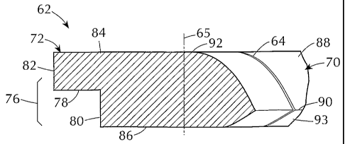
Referring to Figs. 1A, 1B, 3A, 3B and 3C the replaceable floor
edge insert 62, in one embodiment, is in the shape of an annulus, including a
radially inner portion 70 and a radially outer portion 72. The radially outer
portion 72 (Fig. 3C) has a step-like formation 76, also referred to as a
mating
profile, that includes a generally horizontal surface 78 and spaced vertical
surfaces 80 and 82. The replaceable floor edge insert 62 also includes upper
and
lower horizontal surfaces 84 and 86.
-9-
CA 02473421 2004-07-14
WO 03/062353 PCT/US03/01486
The radially inner portion 70 (Fig. 3C) of the replaceable floor
edge insert 62 is curved downwardly and radially inwardly at 88 from the upper
horizontal surface 84 toward ridge 90, relative to the gasifier axis 44. The
intersection or tangency between the upper horizontal surface 84 and the
curved
surface 88 is shown as the circle 92 in Fig. 3A. The radially inner portion 70
(Fig. 3C) is also curved upwardly and radially inwardly at 93 from the lower
horizontal surface 86 toward the ridge 90. Radially oriented thermal expansion
slots 64 (Fig. 3A, 3B and 3C), approximately 5mm wide, are formed or cut into
the radial inner surface 70 and extend from the ridge 90 to a location line 65
(Fig. 3C) that is slightly beyond the tangency circle 92.
The horizontal floor portion 60 (Fig. 1B) is formed or machined
with a finished edge 94 that has a step-like formation, also referred to as a
mating profile. The mating profile of the finished edge 94 is of complementary
shape to the step-like formation 76 at the radially outer portion 72 of the
replaceable floor edge insert 62. Thus the mating profile of the finished edge
94
can engage the mating profile of the radially outer portion 72 of the
replaceable
floor edge insert 62 in the manner shown in Figs. IA and lB.
As most clearly shown in Figs. 3A and 3B the replaceable floor
edge insert 62 is of annular form to correspond to the periphery of the
finished
edge 94 of the horizontal floor portion 60. The inner diameter of the insert
62
will depend on the size of the gasifier and can range from below 18 inches in
diameter to above 50 inches in diameter.
It should be noted that the periphery of the finished edge 94 may
not be exactly circular and can be of any or other geometrical shape that
corresponds to the geometry of the gasifier 10. Thus the replaceable floor
edge
insert 62 will have a periphery that corresponds to the periphery of the
finished
edge 94 of the floor portion 60.
Preferably the mating geometries or mating profiles of the
replaceable floor edge insert 62 and the finished edge 94 of the floor portion
60
-10-
CA 02473421 2004-07-14
WO 03/062353 PCT/US03/01486
will enable the replaceable floor edge insert 62 to remain in engagement with
the finished edge 94 simply by gravity. Thus installation and/or replacement
of
the replaceable floor edge insert 62 can be accomplished in substantially less
time than is required for conventional repair of a gasifier floor.
The replaceable floor edge insert 62 is preferably fitted to the floor
portion 60 as a single unitary annulus. To facilitate installation of the
replaceable floor edge insert 62, the insert 62 can be formed or cut into two
or
three segmental arcs of substantially equal extent and brought into the
gasifier as
separate segments. The segments or arcs of the insert 62 are then welded into
a
unitary construction in the gasifier prior to installation because it may be
difficult or impossible to bring the replaceable annular insert 62, as a
single
unitary structure, into the gasifier 10. Installation of the replaceable floor
edge
insert 62 permits relatively easy repair and/or replacement of the insert 62
should there be a need for subsequent repair and/or replacement of the
gasifier
floor.
It should be noted that the replaceable floor edge insert 62 can be
made of an alloy that is much more resistant to thermal and thermal chemical
damage than the normal steel metallurgy of the gasifier shell 12 and gasifier
floor 20. Thus the use of an alloy such as Incoloy825 to form the replaceable
floor edge insert 62 will enable the floor edge insert to have a longer useful
life
than that of a typical floor edge area that is made of the same metal as the
gasifier floor 20.
Other embodiments of the replaceable floor edge insert can be
mated to the horizontal floor portion 60 by means of other different
complementary mating profiles.
Another embodiment of the replaceable floor edge insert is
generally indicated by the reference number 100 in Figs. 4A, 4B and 4C. The
replaceable floor edge insert 100 is formed with a radially outer mating
profile
102 that defines a tenon portion 106 and a mortise portion 108. The
replaceable
=-11-
CA 02473421 2004-07-14
WO 03/062353 PCT/US03/01486
floor edge insert 100 has a radially inner surface 112 that is identical to
the
radially inner portion 70 of the replaceable floor edge insert 62.
Before installing the replaceable floor edge insert 100 at the
horizontal floor portion 60, the floor portion 60 is provided with a finished
edge
(not shown) having a mortise and tenon mating profile complementary to the
tenon
and mortise formations 106 and 108 of the replaceable floor edge insert 100.
As previously described for the replaceable floor edge insert 62,
the replaceable floor edge insert 100 can be brought into the gasifier in two
or
three unwelded sections and welded into a single unitary insert in the
gasifier
before being positioned and engaged with the corresponding mating finished
edge of the floor portion 60.
A further embodiment of the replaceable floor edge insert is
generally indicated by the reference number 120 in Figs. 5A, 5B and 5C. The
replaceable floor edge insert 120 includes a radially outer surface 122 having
an
inclined step-like mating profile 124. The replaceable floor edge insert 120
also
includes a radially inner surface 128 identical to the radially inner portion
70 of
the replaceable floor edge insert 62.
Before installation of the replaceable floor edge insert 120 into the
gasifier the horizontal floor portion 60 is provided with a finished edge (not
shown) of complementary mating profile with the inclined step-like mating
profile 124 of the replaceable floor edge insert 120. The replaceable floor
edge
insert 120 can be formed as a single unitary piece and then cut into two
pieces or
formed as two separate pieces. The separate pieces are brought into the
gasifier
and installed in the manner similar to that described for the replaceable
floor
edge inserts 62 and 100.
It should also be noted that a two or three segment replaceable
floor edge insert can be positioned as separate segments at the finished edge
of
the gasifier floor, without being welded into a unitary annular structure.
However, when unwelded segments of the floor edge insert are installed at the
-12-
CA 02473421 2004-07-14
WO 03/062353 PCT/US03/01486
finished edge of the gasifier floor, the adjacent ends of the unwelded
segments
should have an end to end relationship that provides a keystone type fitting
arrangement.
Referring to Figs. 1A and 1B the refractory 34 includes refractory
bricks, also known as hotface bricks, having a hotface surface 35 that is
directly
exposed to the environment in the gasification portion 16 of the gasifier 10,
where
gasification occurs. Hotface bricks are also provided at the throat 22 and
generally wear faster than most other refractory bricks in the gasifier.
Hotface
bricks at the throat 22 thus need periodic replacement while major sections of
the
refractory 34 elsewhere in the unit often may remain in place for continued
usage.
Each individual hanging brick 66 (Figs. 1A, 1B and Figs. 6A-6D)
includes a top portion 132, opposite side portions 134 and 136, opposite end
portions 140 and 142 and a bottom portion 144. The bottom portion 144
includes an appendage 150. The end portion 140 is of relatively short height
and
the appendage 150 extends a predetermined amount below-the end portion 140.
The appendage 150 is preferably formed such that the opposite end portion 142
is of relatively long height. The vertical extent of the appendage 150, which
is
the hanging portion of the refractory brick 66, is approximately equal to the
difference in height between the relatively short end 140 and the relatively
long
end 142 but is largely dictated by the thickness of the floor portion 60.
As most clearly shown in Fig. 6C the opposite side portions 134
and 136 diverge slightly with respect to each other, and the opposite end
portions 140 and 142 are slightly curved. The diverging side portions 134 and
136, and the slightly curved end portions 140 and 142 are so formed because
adjacent bricks 66 are arranged around a circular periphery of the throat 22.
Referring to Figs. 1A and 1B the hanging brick 66 is installed at
the throat portion 22 of the gasifier to overlie the upper surface 84 (Fig.
3C) of
the replaceable floor edge insert 62, and to overhang the radially inner
portion
70 of the replaceable floor edge insert 62. The appendage 150 (Fig. 1B) of the
-13-
CA 02473421 2004-07-14
WO 03/062353 PCT/US03/01486
refractory hanging brick 66 also overhangs an upper surface portion 42 of the
quench ring 40. The appendage 150 thus provides protection for the radially
inner portion 70 of the replaceable floor edge insert 62 and also provides
protection for the upper surface 42 of the quench ring 40 to prevent
accumulation of slag, which can solidify and accumulate on the cool, upper
surface of the quench ring. Such slag accumulation can lead to pluggage of the
throat 22 and/or damage to the quench ring 40. Protection provided by the
hanging brick 66 prolongs the life of the gasifier floor and the quench ring
40.
A refractory ceramic fiber paper 154 rated for at least 3000 F and
approximately 6mm thick, for example, is provided between the refractory
hanging brick 66 and the replaceable floor edge insert 62 and held in place
with
a suitable organic adhesive. The refractory paper 154 (Fig. 1B) also extends
between the appendage 150 and the upper surface 42 of the quench ring 40.
A single coil of refractory ceramic fiber rope 156 approximately
13mm in cross-section, for example, (Fig. 1B) is provided at the radially
inner
portion 70 of the replaceable floor edge insert 62, at the upper surface 42 of
the
quench ring 40 and underneath the refractory ceramic fiber paper 154. The
refractory rope 156 is held in place by a suitable organic adhesive. The
refractory
hanging brick 66 helps envelop the refractory ceramic fiber rope 156 between
the
appendage 150 of the hanging brick, the radially inner portion 70 of the
replaceable floor edge insert 62, and the upper surface 42 of the quench ring
40.
The refractory ceramic fiber paper 154 and the refractory ceramic
fiber rope 156 help minimize the conductive and convective heating of the
floor
edge and the upper curved surface of the quench ring , thereby reducing
thermal
stresses and the likelihood of high temperature corrosion of these components.
The refractory ceramic fiber paper 154 and the refractory ceramic fiber rope
156
also reduce the amount of conductive cooling experienced by the refractory
hanging brick 66, which is beneficial since high thermal gradients cause high
thermal stresses and increased risks of cracking the refractory hanging brick
66.
-14-
CA 02473421 2004-07-14
WO 03/062353 PCT/US03/01486
A known ring-like gasket 160 formed of coiled stainless steel
ribbon impregnated with graphite is also provided between the quench ring 40,
and the floor portion 60 and replaceable floor edge insert 62, to enhance the
cooling effect of the quench ring upon the replaceable floor edge insert 62
and
the floor portion 60, and to create a gas tight barrier between these
components.
When installing the refractory hanging brick 66, it is preferred that
no mortar be applied to the bottom surface 144 in contact with the refractory
ceramic fiber paper 154, since mortar would substantially reduce or eliminate
the desirable insulating characteristics of the refractory ceramic fiber paper
154.
The refractory hanging brick 66, by covering the replaceable floor
edge insert 62, enhances the life of the gasifier floor 60 and also enhances
the
life of the quench ring 40. However, the hanging refractory brick 66 can also
be
used to protect gasifier floors with non-replaceable exposed leading edges.
Some advantages of the invention evident from the foregoing
description include a replaceable floor edge insert that is easily installed
and
removed from a gasifier thereby hastening and simplifying a floor repair
operation. Another advantage of the replaceable floor edge insert is that it
can
be made more resistant to thermal and thermal chemical damage then the normal
metallurgy of the gasifier floor. A further advantage is the provision of
hanging
refractory brick with an appendage that provides a refractory shield for the
floor
edge and the quench ring. Prolongation of the operational life of the gasifier
floor and the quench ring helps minimize shutdown periods of the gasifier and
increases the productivity and profitability of the gasifier operation.
A further advantage is the provision of a novel method of
facilitating the repair of a metal gasifier floor by incorporating a
replaceable
floor edge insert at a throat opening and a novel method of prolonging the
life of
the metal gasifier floor at the throat opening, by providing hanging
refractory
brick with an appendage to overlie the replaceable floor edge insert. The
hanging refractory brick with the appendage thus covers the replaceable floor
-15-
CA 02473421 2004-07-14
WO 03/062353 PCT/US03/01486
edge insert and also covers a vulnerable surface of a quench ring that
underlies
the gasifier floor at the throat opening.
In view of the above it will be seen that the several objects of the
invention are achieved and other advantageous results attained. As various
changes can be made in the above constructions and methods without departing
from the scope of the invention, it is intended that all matter contained in
the
above description or shown in the accompanying drawings shall be interpreted
as illustrative and not in a limiting sense.
-16-