Note: Descriptions are shown in the official language in which they were submitted.
CA 02473658 2004-07-16
WO 02/058250 PCT/US02/01153
CARRIER PHASE RECOVERY SYSTEM FOR ADAPTIVE BURST MODEMS
AND LINK HOPPING RADIO NETWORKS
BACKGROUND
This invention relates to a carrier phase recovery subsystem employed in
fixed Broadband Wireless Access (BWA) applications operating in adaptive burst
modems and multi-link hopping mesh radio networks over slow time-varying
channels. The adaptive modem is capable of fast link-hopping from one link to
another over such channels. That is the channel is quasi-static from burst to
burst
for any given lime.
The embodiments described herein may be used in conjunction with a
wireless mesh topology network of the type described in US Patent Application
serial number 09/187,665, entitled "Broadband Wireless Mesh Topology
Networks" and filed November 5, 1998 in the names of J. Berger and I.
Aaronson,
and with network nodes including switched multi-beam antenna designs similar
to
the de,~ign described in US Patent Application serial number 09/433,542,
entitled
"Spatially Switched Router for Wireless Data Packets" and filed in the names
of J.
Berger, et al., as well as with the method and apparatus disclosed in U.S.
Patent
Application serial number 09/699,582 entitled "Join Process Method For
Admitting A Node To A Wireless Mesh Network, filed October 30, 2000 in the
names of Y. Kagan, et al. Each of these U.S. patent applications is
incorporated
herein by reference.
Burst transmission of digital data is employed in several applications such
as satellite time-division multiple access, digital cellular radio, wideband
mobile
systems and broadband wireless access systems. The design trade-offs and the
resulting architectures are different in each of these applications.
In most of these applications, a preamble of known symbols is inserted in
the beginning of each burst of data packets for synchronization purposes. Data-
aided (DA) algorithms are normall« employed for good performance for short
preamble. However, synchronization becomes difficult at low values of signal-
to-
noise ratio (SNR).
CA 02473658 2004-07-16
WO 02/058250 PCT/US02/01153
2
Coherent detection schemes are superior compared to differential coherent
or non-coherent schemes in terms of power efficiency. However, carrier phase
recovery required for coherent detection is influenced by a time-varying
characteristic of a fading channel. The power efficiency presented by coherent
S detection in a digital communication system is effective only if carrier
phase
synchronization techniques are provided for the receiver.
A constant need for ever-increasing throughputs through fixed bandwidths,
fueled by broadband IP (Internet protocol) applications, has pushed system
designers toward more throughput-efficient modulation schemes. Because of
their
relatively good performance, large quadrature amplitude modulation (QAM)
constellations are being used in many of these applications. One of the
critical
problems associated with the use of large QAM constellations is that of Garner
phase estimation, which for efficiency reasons, must often be done without the
use
of a preamble, particularly in burst modem applications. The problem is
further
complicated for cross-tally interference between the quadrature components
(i.e.,
I/Q channels).
For coherent detection, there are two basic approaches to establish carrier
phase synchronization at the receiver. One is pilot based where a known signal
is
inserted at the transmitter that allows the receiver to extract the pilot
symbol and
synchronize its local oscillator to the carrier phase of the received signal.
Known
symbols are multiplexed with the data sequence in a ratio of p pilots to m
data
symbols. At the receiver, the incoming waveform is filtered and sampled at the
symbol rate. The sample sequence is split into two streams; a data stream and
a
reference stream of known symbols. The latter is decimated and only the
samples
corresponding to pilot symbols are used for further processing. A narrow band
phase-locked loop (PLL) is typically employed to acquire and track the carrier
component of the received signal.
Such an approach is not appropriate in applications involving transmission
of short bursts. The insertion of a known data sequence greatly reduces the
CA 02473658 2004-07-16
WO 02/058250 PCT/US02/01153
3
transmission efficiency for a short burst. As a result, pilot-aided algorithms
are
not applicable in such systems.
In the second approach, the Garner phase estimate is derived directly from
the modulated signal. This approach is much more prevalent in practice due to
its
distinct advantage that the total transmitter power is allocated to the
transmission
of the data symbols. Transmission efficiency is optimized.
The effect of carrier phase error, ~e = ~ - ~ , in high-level modulation
schemes, such as M-QAM is to reduce the power of the desired signal component
by a factor of cost (ø - ~) in addition to the cross-tally interference from
the in-
phase and quadrature components. Since the average power level of the in-phase
and quadrature components is the same, a small phase error causes a large
degradation in performance, particularly at higher modulation levels (i.e.,
M >_ 16 ).
In continuous modem applications, the user is typically willing to wait a
few seconds while the receiver goes through an acquisition phase in which
tracking processes converge. Often, the acquisition process in a continuous
modem simply allows phase-locked loops to pull in on the received signal. In
other words, the acquisition processing is not different from the tracking
processing.
In contrast, in a burst modem, the user data content of a given transmission
may be only a fraction of a millisecond. Long acquisition times contribute an
unacceptable level of overhead to the system and substantially reduce
capacity.
Thus, the burst modem requires a special acquisition process that will quickly
estimate the appropriate receiver gain, the carrier frequency and phase, the
sample
timing frequency and phase, and, if needed, the equalizer taps for an
equalizer of
the receiver. Also, the acquisition process must reliably identify which bit
in the
burst is the first user data bit so that higher layers of the protocol stack
can format
data properly.
The initial carrier phase can be estimated using the phase of the output of a
coherent correlator. This phase is an estimate of the phase of a sample in the
CA 02473658 2004-07-16
WO 02/058250 PCT/US02/01153
4
middle of the preamble. If we desire estimates of the phase at the beginning
or the
end of the preamble, the estimate from the middle must be compensated by the
frequency error estimate. Since the frequency error estimate is not perfectly
accurate, use of it for this compensation will degrade the accuracy of the
phase
estimate formed for the preamble ends. Thus, it should be carefully considered
whether to start tracking from either end of the preamble or whether starting
in the
middle is the best route.
Another important design decision is the choice of the estimator topology.
In continuous modem applications, closed-loop (feedback) structure is commonly
used with relatively high performance depending on the application. However in
burst modem systems, closed-loop structures do not'produce the best results.
Feedback systems require, in general, longer tracking time (i.e., long data
sequence) for an acceptable performance level in many applications. This
requirement is typically not met in burst modems where the burst length could
be
iri the low microseconds (i.e., 20 to 40 octets).
Accordingly, there is a need for a method and apparatus for carver phase
recovery in a burst mode system. Further, there is a need for a method and
apparatus for Garner phase recovery in a link hopping system using
transmission
bursts for radio communication.
BRIEF SUMMARY
By way of introduction only, the present invention provides a method for
receiving radio signals in a multiple-link hopping radio system. The method
includes hopping among a plurality of radio links to receive bursts of radio
signals
on the plurality of radio limes and determining channel information for each
radio
link from a received burst on the radio link. Further, the method includes
storing
the determined channel information and using the determined channel
information
for the radio lime to reliably receive a next received burst on the radio
link.
The invention further provides a method for receiving radio signals which
includes receiving a first burst of a first radio signal on a first radio link
and
determining channel information about the first radio link using the first
burst.
CA 02473658 2004-07-16
WO 02/058250 PCT/US02/01153
The method further includes receiving a next burst such as a second burst of
the
first radio signal or a first burst of a second radio signal on a second radio
link and,
subsequently, receiving a next burst of the first radio signal on the first
radio link
using the channel information.
S The invention further provides a carrier phase recovery method for use in a
multiple-link hopping, burst adaptive modem. The method includes receiving a
modulated carrier signal as a series of bursts, each burst including one or
more
pilot symbols and data symbols and forming a coarse estimation of carrier
phase
using the one or more pilot symbols. Further, the method includes forming a
fme
estimation of carrier phase using the coarse estimation of carrier phase to
estimate
carrier phase for a burst using data symbols of the burst, and correcting
Garner
phase for the radio signal using the fine estimation of carrier phase.
The invention further provides carrier phase recovery system. The system
includes a fixed equalizer configured to equalize a present burst of data
using
equalizer weights from a previous burst of data generated by an adaptive
equalizer. The present burst of data includes pilot symbols and data. The
system
further includes a carrier phase recovery unit which recovers phase for the
present
burst of data using the pilot symbols and a mixer combining a delayed present
burst of data and the recovered phase. The system still furtlier includes an
adaptive equalizer which equalizes the present burst to produce an equalized
output signal and provides next burst equalizer weights to a fixed equalizer
for
equalizing a next burst of data.
The invention further provides a phase correction apparatus which includes
in one embodiment means for receiving a distorted signal and means for
compensating for the phase of the distorted signal. The compensating means
includes means using known pilot symbols in the distorted signal for obtaining
a
coarse estimate of carrier phase for the distorted signal, and means using
data
symbols of the coarse phase-compensated signal to produce a fine carrier phase
estimate.
The invention further provides a carrier phase recovery system for use in a
multiple-lime hopping and burst adaptive modem in steady state operation. In
one
CA 02473658 2004-07-16
WO 02/058250 PCT/US02/01153
6
embodiment, the carrier phase recovery system includes a memory and a fixed
equalizer for equalizing a present data burst of a present link for which the
tap
coefficients pertinent to a previous burst. The carrier phase unit includes a
first
stage which acquires a coarse estimate of the carrier phase offset using a
pilot-
s aided technique using multiple known pilot symbols contained in the present
burst
of data, a fixed phase bias removal stage coupled to the first stage and a
phasor
generating stage' coupled to the fixed phase bias removal stage. The carrier
phase
unit further includes a de-rotating means for de-rotating the filtered
(equalized)
signal by a phasor signal generated by the phasor generating stage to remove
estimated coarse Garner phase from the filtered signal to produce a coarse
phase-
compensated signal. The Garner phase unit further includes a data-aided phase
estimator stage for removing modulated signal from the coarse phase-
compensated
signal using a data-aided, decision-directed technique, an averaging means for
averaging N symbols from the data-aided phase estimator stage to reduce noise
variance, and an equalizer stage for generating the tap coefficients and
storing the
t,~p coefficients in the memory.
The foregoing discussion of the preferred embodiments has been provided
only by way of introduction. Nothing in this section should be taken as a
limitation on the following claims, which define the scope of the invention.
BRIEF DESCRIPTION OF SEVERAL VIEWS OF THE DRAWINGS
FIG. 1 is a block diagra;n of a link hopping wireless network having a
mesh topology;
FIG. 2 shows a general block diagram of a prior art maximum likelihood
(ML) carrier phase recovery system;
FIG. 3 illustrates frame construction of a transmitted burst in the wireless
network of FIG. 1;
FIG. 4 is a block diagram of a carrier phase synchronization system for use
in a node of the wireless network of FIG. 1 in burst-mode operation;
FIG. S is a detailed block diagram of a carrier phase recovery unit for burst-
mode operation of the wireless network of FIG. 1;
CA 02473658 2004-07-16
WO 02/058250 PCT/US02/01153
7
FIG. 6 shows the frame structure of transmitted burst for pilot acquisition
in a pilot-aided acquisition unit employed in the joining process for the
wireless
network of FIG. 1; and
FIG. 7 is a detailed block diagram of a carrier phase recovery unit for the
joining process of the wireless network of FIG. 1.
DETAILED DESCRIPTION OF THE PRESENTLY PREFERRED
EMBODIMENTS
This invention relates to the carrier phase recovery subsystem for a link-
hopping wireless mesh network topology used for Broadband Wireless Access
(BWA) networks. Such networks operate in different spectra such as in the
Local
Multi-point Distributed Service (LMDS) band at 2~ GHz. The modem of a node
in such a network is capable of fast lime-hopping from one link to another
over
slow time-varying channels. That is, the channel is quasi-static from burst to
burst
for any given link. A carrier phase estimation technique is provided for a
coherent
detection of high-speed short-burst multi-link hopping mesh network topology
using, for example, fixed Broadband Wireless Access (BWA).
Fading in fixed line-of-sight (LOS) channels, although mild compared to
mobile systems, provides disruptive effects for phase tracking. The use of
closed-
loop systems, such as phase-locked loops or modified Costas phase trackers, is
not
appropriate for burst modem applications. In these environments, closed-loop
systems typically fail to provide improved performance due to their large
cycle-
slip rate in fading channels and/or slow convergence rate in short-burst
broadband
applications.
The present embodiments are designed to enhance performance as
compared to non-coherent M-ary modulation schemes through employing fast and
efficient algorithms, while maintaining low-implementation complexity and high-
throughput efficiency. A pilot-aided coherent phase estimation technique along
with a decision-directed scheme are the scope of this embodiment for
extracting
the carrier phase of the transmitted signal in a time-varying channel
environment
involving a dynamic mesh networks employing high-speed, short-burst data.
CA 02473658 2004-07-16
WO 02/058250 PCT/US02/01153
8
To achieve coherent detection in a short-burst and high-speed mesh
infrastructure, reliable carrier phase recovery must be performed. In
principle,
non-aided schemes alone are most efficient, however, their performance becomes
critical even for a very robust modulation signaling (i.e., B/QPSI~) when
operating
in low signal-to-noise ratio (SNR) and/or the channel is impaired by fading.
In the burst mode, the carrier phase recovery unit of the present
embodiments conducts a multiple-stage phase recovery scheme. First, the
received signal is matched filtered and is passed through a fined T/N-spaced
equalizer to compensate for the phase and amplitude variations of the link
under
the operation. When a new burst of a particular link is received in the mesh
topology (mufti-point to mufti-point), the weights of the fixed equalizer for
that
link are updated based on the tap coefficients of an equalizer which has
operated
on the previous burst of the corresponding link. In this embodiment, the tap
coefficients of the fixed equalizer are loaded from memory into a T/2-spaced
equalizer. That is, in the present embodiments, each node has N sets of tap
coefficients stored in its local memory correspor.~.ding to its N neighboring
nodes.
The present embodiments provide a novel and improved method and
system for carrier phase recovery. The estimation of carrier phase is
conducted in
two distinct modes. The first mode is the join mode where a new node is
invited
to join a mesh radio system. In this mode, the carrier phase is estimated
through a
long sequence of known, un-modulated, pilot symbols.
In the second mode, the carrier phase is estimated when the mesh
infrastructure is in a burst or steady-state operation. The focus of this
discussion is
primarily on this mode of the carrier phase estimation. Although there are a
number of traditional closed-loop phase recovery techniques (i.e., PLL, Costar
loop, etc.) available and cited in the literature, the present embodiments
utilizes a
novel mufti-stage open-loop structure to efficiently operate with a burst
modem
within the existing mesh network capable of link hoping on a burst by burst
basis.
FIG. 1 is a block diagram of an exemplary wireless radio network 100
employing a mesh topology. The network 100 as illustrated in FIG.1 includes a
first node 102, a second node 104, a third node 106 and a fourth node 108 in
radio
CA 02473658 2004-07-16
WO 02/058250 PCT/US02/01153
9
communication. The network 100 may include any number of nodes. The fear
nodes shown in FIG. 1 are exemplary only. In the embodiment of FIG. 1, the
network 100 is a wireless mesh topology network of the type described in US
Patent Application serial number 09/187,665, entitled "Broadband Wireless Mesh
Topology Networks" and filed November 5, 1998 in the names of J. Berger and I.
Aaronson.
Each node 102, 104, 106, 108 includes data processing apparatus and a
radio for communication of data with remote radios, such as other nodes of the
network 100. Each node in the exemplary embodiment includes a directional
antenna that provides radio communication on a number of sectors. The sectors
provide radio coverage over a portion of the geographic area near a node.
Thus,
node 104 includes sectors 112 providing coverage over an area 116 which
includes
node 102. Node 102 provides coverage over an area 114. Node 106 provides
coverage over an area 118, and node 108 provides coverage over an area 120.
Nodes 102, 104, 106, 108 of the network 100 are considered peers. They
are free to communicate with one another on an equal basis. This is in
distinction
to a hierarchical system such as base stations communicating with subscriber
units
in a cellular radiotelephone system. Communication among the nodes 102, 104,
106, 108 is peer-to-peer communication.
Two nodes are in radio communication when their antenna sectors align.
In that case, the nodes may complete a radio link and exchange data and
control
information. Thus, node 102 and node 104 communicate on link 128, node 102
and node 108 communicate on link 126, and node 104 and node 108 communicate
on a link 134.
The fixed broadband wireless network 100 operates in two modes. A first
mode is referred to as the acquisition/join mode. A second mode is referred to
as
the steady-state or burst bode. Operation will be described in greater detail
below
in conjunction with FIGS. 3-5. In the first mode of operation, the present
invention obtains an accurate estimate of the carrier phase through averaging
the
estimated phase of K inserted pilot symbols into the designated slot of the
join
packet. In one embodiment, K=32. The join process will be described in greater
CA 02473658 2004-07-16
WO 02/058250 PCT/US02/01153
detail below in conjunction with FIGS. 6 and 7. The join process may be of the
type described in U.S. Patent Application serial number 091699,582 entitled
"Join
Process Method For Admitting A Node To A Wireless Mesh Network, filed
October 30, 2000 in the names of Y. Kagan, et al.
5 In the exemplary embodiment of FIG. 1, node 106 may be considered a
joining node which is in the process of joining the network 100 including
existing
nodes 102, 104, 108. The joining node 106 receives invitation packets from the
existing nodes 102, 104, 108 and can thus establish radio communication with
node 102 on a link 130 with node 103 and on a link 132 with node 108.
10 . FIG. 2 is a block diagram of a prior art maximum likelihood carrier phase
recovery system 200. FIG. 2 illustrates a generic block diagram of a Maximum
Likelihood (ML) phase estimator. The parameter f is the frequency offset, z
represents the timing phase, {d (m)~ are the information symbols, g(k) is the
square-root raised-cosine matched filter (signaling pulse shape), T is the
symbol
period, and B is the carrier phase to be estimated.
All parameters, . f , z , ~d (ffz) }, and the pulse-shaping filter, g(k) , are
assumed to be known to the receiver. The phase. B is the only unknown
constant,
taking values in the range of ~ ~.- The knowledge of the data symbols may come
from either a decision-directed scheme or a known preamble (pilot symbols).
The
symbol epoch and carrier frequency values are estimated in advance and
indepem ently of carrier phase and are accurately tracked between bursts.
The system 200 illustrates the operations necessary to recover the carrier
phase in a radio receiver of the system 100. The system 200 is an idealized or
canonical representation. Actual embodiments of a system which can accomplish
the illustrated operations requires an accurate and efficient estimate of
{d(zzz)}
within the context a multi-hopping link system. Forming an effective and
efficient
embodiment is particularly compounded in the present system where short bursts
comprising the pilot signal of only two symbols are implemented for system
efficiency reasons.
CA 02473658 2004-07-16
WO 02/058250 PCT/US02/01153
11
The carrier phase recovery system 200 includes a mixer 202, a filter 204, a
sampler 206, a multiplier 208, a summer 210 and an angle determination block
212. The system 200 receives a signal r(k) which includes received data
samples.
The filter 204 is a matched filter having a filter response g( k) which
matches to
the transmitter pulse shaping filter g(k) .
The sampler 206 samples the output signal every T seconds, producing the
signal x(k) which has a timing phase shift equal to z . The multiplier 208
multiplies the signal x(k) by the signal ~d' ~ which is a known signal or
known
data, or an estimate thereof. In the present embodiment, d' is a known pilot
signal in the first stage of the carrier phase recovery system and an estimate
of an
unknown data in the second stage, respectively. The product signal which is
provided to the summer 210. The multiplier 208 de-rotates the received signal.
The summer 210 averages symbols over a time period corresponding to an
observational window of interest. The angle determination block 212 extracts
the
angle associated with the data and produces an angle B. This angle corresponds
to
the phase offset or phase error of the received data.
As noted above, the system 200 of FIG. 2 is a canonical form for .
estimation of carrier phase. However, in the system of FIG. 1, radio signals
are
received as short bursts including short (e.g., two-symbol) pilot signals.
Also, the
system of FIG. 1 is a link hopping system in which one radio signal is
received on
a frequency during certain receive times. The receive times may be
interspersed
with times during which other signals are received. The embodiments
illustrated
below relate to a system and method for recovering carrier phase in a link-
hopping, burst-mode radio receiver.
FIG. 3 illustrates a frame format of a transmitted burst 300 in the wireless
network 100 of FIG. 1. The burst 300 is of the type used for on-going, burst
mode
communication among nodes of the network 100 and is distinct from a burst used
in the join process to be described below in conjunction with FIG. 6. The
burst
300 is one example of a data burst. As is shown in FIG. 3, the burst 300
includes
data symbols and known pilot symbols 304 at a known timing position inside the
CA 02473658 2004-07-16
WO 02/058250 PCT/US02/01153
12
data burst. Two pilot symbols are used in the illustrated embodiment, but any
suitable number could be used. The pilot symbols are inserted between data
symbols of the packet data burst 300. The packet may contain any suitable
number of symbols. In the illustrated embodiment, m is the number of data
symbols per packet and is chosen to be 32. This frame structure embeds the
pilot
symbols in the data for reliable phase estimation and data recovery.
The present embodiments include a carrier phase estimation unit which
includes a faced equalizer to compensate for the phase and amplitude
variations of
individual limes capable of operating on multiple links independently, a pilot-
symbol-based estimation apparatus to produce a coarse estimate of the value of
the
carrier phase, a decision-directed phase recovery method to provide the
estimates
of the symbol data in order to remove the modulating signals, and an averaging
and phase extraction means to generate the final phase estimate.
The combination of a fixed equalizer, pilot-based coarse phase estimation,
decision-directed data estimator, a smoothing filter, and a phase extractor
means
over M symbols which are all implemented in an open loop (feed-forward)
structure brings about improvements in carrier phase tracking capability and
provides an accuracy which is very close to the Modified Cramer-Rao bound
(MCRB (~ ). The individual aspects of the present embodiments each provide
respective system and performance enhancements when used alone or in
conjunction with either prior art designs or disclosed elements.
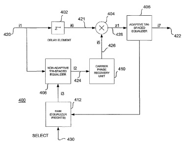
FIG. 4 is a block diagram of a carrier phasi; synchronization system 400 for
use in a node of the wireless network of FIG. 1 in burst mode operation. The
system 400 forms an overall carnet phase recovery system. 'The system 400 may
be implemented in a radio receiver which receives a modulated signal as a
series
of bursts of data on a plurality of links in a link hopping radio
communication
system such as the system 100 of FIG. 1. In particular embodiments, each burst
may include one or more pilot symbols and data symbols. In one embodiment, the
radio receiver including the system 400 operates in the local muitipoint
distribution service (LMDS) band at 2~ GHz on a channel that is slowly
changing
CA 02473658 2004-07-16
WO 02/058250 PCT/US02/01153
13
with time. The radio receiver receives broadcasts of quadrature amplitude
modulated (QAM) data. The radio receiver hops among a plurality of radio links
to receive bursts of radio signals on the plurality of radio links. Depending
on the
configuration of the particular network, the bursts received at the receiver
on a
particular channel from a particular transmitter may be interleaved with
bursts
from other transmitters on other channels. Applications with other systems
having
other operational features are possible, as well.
In this exemplary embodiment, each burst of data may have the format
illustrated in FIG. 3. The pilot symbols are chosen to be at maximum amplitude
corners of the QAM constellation. As shown in FIG. 3, in the time domain, the
pilot symbols may be located near the center of the burst, which is, for
example,
32 symbols in duration. The carrier phase synchronization system 400 of FIG. 4
uses the inserted pilot symbols and the estimated data symbols to accurately
recover the carrier phase offset for the short bursts.
The system 400 includes a delay element 402, a mixer or multiplier 404
and an adaptive equalizer 406. The system further includes a non-adaptive
equalizer 408, a carrier phase recovery unit 410 which recovers phase for the
present burst of data using pilot and data symbols, and a memory circuit 412.
Upon receipt of an initial burst (signal il in FIG. 4) at an input 420, the
burst or
symbols of the burst is delayed in the delay block 402. The delayed data
(signal i6
in FIG. 4) on line 421 are multiplied in the multiplier by a carrier phase
estimate
(signal i5 in FIG. 4) on line 426 from the carrier phase recovery unit 4 i 0.
The
multiplier or mixer 404 combines a delayed present burst of data and the
recovered phase estimate to produce a phase-error compensated signal (signal
zl
in FIG. 4) on the line 428. Structure and operation of the carrier phase
recovery
unit 4I0 will be described in more detail below in conjunction with FIG. S.
The output signal zl from the multiplier 404 is provided on line 428. The
signal is provided to the adaptive equalizer 406 which compensates for phase
and
amplitude variations of the channel. The equalizer 406 produces an equalized
output signal (signal i7 in FIG. 4) and provides next burst equalizer weights
to the
fixed equalizer 408 for equalizing a next burst of data. In the illustrated
CA 02473658 2004-07-16
WO 02/058250 PCT/US02/01153
14
embodiment, the next burst equalizer weights are stored in memory 412 but
separate storage may be omitted. The equalizer 406 performs a T/N-spaced
adaptive equalization process and an equalized and carrier phase error
compensated signal is produced at the output 422. As part of the adaptive
equalization process, equalizer weights are produced by the adaptive equalizer
406. These equalizer weights correspond to the particular lime from which
received radio signals are currently processed. The adaptive equalizer 406
compensates for amplitude and carrier phase variations in the channel and/or
provides appropriate channel side information for each radio link from the
received burst on the radio link. Other techniques of characterizing the
channel or
link may be used instead of or in addition to determining equalizer weights or
carrier phase.
The equalizer weights, channel phase or other determined channel
information are stored in the memory 412. In the illustrated embodiment, the
memory 412 is a random access memory. In alternative embodiments, other
storage devices may be substituted. In a link-hopping network embodiment, such
as the network 100 of FIG. 1, the equalizer weights are preferably stored in
accordance with an indication of the link with which they are associated. In
this
manner, in response to a select signal received at an input of the memory 430,
the
equalizer weights may be retrieved (signal i3 in FIG. 4) from the memory 412
for
use in equalization of a subsequent burst. When each subsequent burst for a
particular link is received, the adaptive equalizer 406 updates the equalizer
weights for the next received burst using the current equalizer weights or
other
determined channel information from a received burst. The adaptive equalizer
406
then stores the updated equalizer weights in the memory 412.
The equalizer 408 receives the stored equalizer weights as signal i3 from
the memory 412. As noted, in a multiple-link or link-hopping system, the
stored
equalizer weights are preferably retrieved from the memory according to the
link
to be received. The equalizer 408 uses the equalizer weights or other
determined
channel information for the radio link to reliably receive a next received
burst on
the radio link. That is, when the next burst for that particular link is
received, the
CA 02473658 2004-07-16
WO 02/058250 PCT/US02/01153
SELECT signal is asserted at the input 430 to the memory 412 to retrieve the
equalizer weights previously stored for the link. The equalizer 408 produces
an
equalized signal using the retrieved equalizer weights. The equalized signal
is
provided to the tamer phase recovery unit 410 on a line 424.
FIG. 4 illustrates the top-level block diagram of the tamer phase estimator
unit according to one embodiment in which a carrier phase synchronizer and a
fixed or non-adaptive equalizer 408 preceding the phase estimator 410 are
combined. The non-adaptive equalizer 408 pre-compensates for the phase and
amplitude variations of the received symbols of the j -th burst of the l-th
link,
10 l =1,..., N (where N is the number of neighbors associated with any given
node.)
The tap coefficients of the fixed equalizer 408 are the same as the tap
coefficients
of an adaptive equalizer employed after the carrier phase recovery unit 410
operated on the j -1-st (previous) burst of the l -th link.
In the preferred embodiment, the carrier phase recovery unit 410 provides the
15 carrier phase estimates of every j-th burst of all N neighboring links,
~E(j,l);l =1,..,1V~, independently. The carrier phase recovery means is
employed in
one application in a mufti-hopping link topology such as a mesh architecture.
All
elements of the present invention axe preferably constructed in a digital
system.
The transmitted signal, channel multiplicative distortion, and the additive
white Gaussian noise corresponding to the j -th burst of the l-th link at the
sam; ling instant i are denoted by the complex signals s(i, j, l) ,
c(i, j,l) = e~(i, j,l)e'~~'~'~'~and n(i, j,l), respectively. Then, the
received symbols for
the l-th link is defined as:
il(i, j,l)=c(i, j,l) ~s(i, j,l)+n(i, j,l) 1)
The received complex signals are assumed to be carrier frequency offset
corlpensated, matched filtered, and the timing phase parameter is accurately
CA 02473658 2004-07-16
WO 02/058250 PCT/US02/01153
16
estimated, before being processed through a fixed (non-adaptive) fractionally-
spaced equalizer and carrier phase recovery means as described above.
In the steady-state (burst) operation of the carrier phase estimator unit, the
received signal, il, is first filtered through a fixed T/2-spaced equalizer
408 (FIG.
4) to compensate for any phase and amplitude variations experienced in the
slow-
varying fading environment. The tap coefficients of the faced equalizer 408
are
provided by the adaptive T/2-spaced equalizer 406 operated on the previous
burst
of the current link. We denote the tap coefficients of the adaptive equalizer
406 by
{u(l~j,n;k=1,..,L;l =1,..,1V}, where u(l~j,l) is the k-th tap coefficient of
the j-th burst
of the l-th link. The parameters, L, maximum number of tap coefficients, and
N,
maximum number of existing neighbors of the target receiver (inviting node)
are
the design parameters and hence variable.
At the end of each j-th burst of the 1-th link, the tap coefficients,
u(l~j,l), are
stored in the memory 412. These tap coefficients are loaded into the fixed
equalizer 408 for pre-compensating the phase and amplitude variations of the
next
( j+1-st) burst, assuming the channel is slowly changing from burst to burst
for a
given Z-th link. The pre-compensated phase and amplitude of the complex signal
is inputted to the carrier phase recovery unit where,
L
i2(i,j,l)=~u(l~j-l,l)~a'1(i-l5j,n for l=1,..,N 2)
Note that in the preceding notation, the index i is used iriteichangeably for
either the i-th symbol position within the j-th burst or the sampling time,
assuming that one sample per symbol processing is considered.
The delay block 402 in FIG. 4 is provided to account for all processing delays
encountered in the fixed equalizer 408 and the carrier phase recovery unit
410,
respectively.
In the present embodiment of the carrier phase estimation unit 410 in the
steady-state (burst) mode, the multiplexed p pilot symbols of the l -th link
are
CA 02473658 2004-07-16
WO 02/058250 PCT/US02/01153
17
represented by {I-(I,l), 12,1), .., l~p,l)}. For the Garner phase recovery
system,
only two opposite corners of the designated M-QAM (i.e., M = 4, 16, 64 or 256)
constellation points are used as defined by:
j~(i,l)
P(i,l) = r(il)e , 3)
P(i -l,l) = r(i -l,l)eje('-',l)
where r(i,l)=r(i-l,l)and ~(i,l)=-B(i-l,l)=~t14.
In a multiple link environment, the system 400 may receive bursts over
several independent channels from different receivers. At some times, the
system
400 may receive multiple bursts or a continuous transmission from a single
transmitter. In the general case, though, the system 400 receives one burst
from
one transmitter on a first channel and subsequently, a second burst from the
same
transmitter on the same first channel. Bursts from one or more other
transmitters
are interspersed-between the first and second bursts on the channel.
1 S The system 400 thus receives a first burst of a first radio signal on a
first
radio link. For example, in FIG. 1, the node 102, which includes the system
400
in this example, may receive a burst on link 126 from node 108. The system 400
determines channel information, such as the carrier phase, about the first
radio link
using the first burst. The system 400 stores the equalizer weights, carrier
phase or
other channel information. The system 400 then receives a first burst of a
second
radio signal on a second radio link, such as the link 128 in FIG. 1. The
system 400
determines channel information about the second radio link using the first
burst of
the second radio signal. The channel information for the second radio link is
stored. Subsequently, the system 400 receives a next burst of the first radio
signal
on the first radio link, such as link 126 in FIG. 1, using the equalizer
weights or
other channel information.
One embodiment of the carrier phase recovery unit 410 is shown in greater
detail in FIG. 5. FIG. 5 represents the details of Garner phase recovery unit
in
burst mode according to one embodiment. After the amplitude and phase
CA 02473658 2004-07-16
WO 02/058250 PCT/US02/01153
18
variations of the received burst are compensated (minimized) through the fixed
T/2-spaced equalizer for the l-th link (FIG. 4), a coarse estimate of the
earner
phase, B( j, l) , is obtained based on the p pilot symbols in the j -th burst
of the l -
th link, f P(1, j,l),...,P(p, j,l)}. These known symbols are multiplexed
periodically with the data symbols as shown in FIG. 3. Depending on the number
of pilots inserted and the periodicity ( TP = p + m , p pilots for every m
data
symbols, m » p ), conventional techniques known in prior art such as linear
interpolation, low-pass filter interpolation, or Gaussian interpolation can be
applied to obtain the estimates of the channel parameters.
In the preferred embodiment, the estimation of the phase and amplitude
variations of the I/Q components of the available pilot symbols can be
performed.
The value of the amplitude information of a multiplicative distortion obtained
by
this method can also be used to enhance the precision of automatic gain
control
(AGC).
Another added advantage of these periodic pilot symbols is to reduce the
impact of the phase noise. This benefit can be readily realized by performing
a
new estimate of the earner phase (using the available p pilot symbols) every
m data symbols. That is, after every m data symbols, a new estimate of the
carrier phase could be provided. In this case, the phase estimate, B, is
updated
every p + m symbols. These independent carrier phase estimates could be very
instrumental to relax the impact of phase noise particularly in high-leve" QAM
modulation schemes. Since the loop bandwidth of the feed-forward carrier phase
recovery technique is inversely proportional to the period of the integration
or
estimation length of the observed symbols, it is desirable to increase the
periodicity of the inserted pilots or equivalently to reduce the parameter, Tp
. The
pilot sequence period (TP ) is a design parameter which should be set based on
a
trade-off metric between the desired phase noise reduction and the throughput
efficiency.
CA 02473658 2004-07-16
WO 02/058250 PCT/US02/01153
19
The carrier phase recovery unit 410 uses a pilot based and decision aided
algorithm for phase estimation. The signal to be received is a series of
bursts,
each burst having a number of pilot symbols, preferably located near the
center of
then shortest burst. The carrier phase recovery unit 410 provides carrier
phase
recovery in burst mode applications.
The burst-mode of the carrier phase recovery unit 410 relies on a coarse
estimate of the carrier phase utilizing p pilot symbols multiplexed with the
data in
the transmitted burst. In this embodiment, two opposite corner symbols (i.e.,
p = 2) of the M-QAM constellation are assigned as pilot symbols. The current
embodiment inserts these two known symbols adjacent to one another in the
middle of the data stream in a pre-assigned time slot.
In a preferred embodiment, the pilot symbols can be used for estimation of
multiplicative amplitude distortion of a fading channel. Pilot symbol assisted
modulation (PSAM) is an alternative to a transparent tine-in-band (TTIB)
method.
The periodically inserted pilot symbols are interpolated to generate the
estimates
of time-varying channel parameters such as phase and amplitude distortions.
These pilot symbols can be used to reduce the impact of the phase noise.
In order that the variations of amplitude and phase caused by the
modulation of a Garner, the modulation must be removed. Such variations are
from the distortions by the fading channel and other residual impairments
caused
by the radio transceiver. After the phase of the burst is de-rotated by a
coarse
estimate of the carrier phase, the modulating data of the information-bearing
symbols are removed through a decision-directed phase recovery apparatus. The
fine measurement of the phase is now carried out over these M symbols. The
resulting unmodulated symbols are processed through a non-causal averaging
unit
to smooth out the carrier phase estimate of the first M symbols of the burst.
The
parameter M is selected based on the burst length and the channel condition.
In
the embodiment described herein, a value of M=32 is used. Other values could
be
used in other designs. This smoothing process, improves the accuracy of the
CA 02473658 2004-07-16
WO 02/058250 PCT/US02/01153
estimated phase value significantly and enhances the reliability of the phase
estimate through reducing the impact of the additive white Gaussian noise.
In the embodiment of FIG. 5, a two-stage phase recovery technique is used
on each burst. Thus, the carrier phase recovery unit 410 includes a coarse
carrier
5 phase estimation circuit 502 and a fme carrier phase estimation circuit 504
to
produce the recovered phase. The coarse carrier phase estimation circuit 502
is
configured to produce a coarse estimate of the phase for the present burst of
data
using the pilot symbols of the present burst of data. The fme carrier phase
estimation circuit 504 is coupled to the coarse carrier phase estimation
circuit to
10 produce the recovered phase using the coarse estimate of the phase and at
least
some of the data contained in the burst.
FIG. 5 illustrates the detailed block diagram of the carrier phase recovery
unitt
410 employed in a burst mode. After the received signal is phase and amplitude
compensated by the fixed equalizer the pilot symbols, pl and p2 are
demultiplexed
15 by the block 506 and processed to obtain a coarse estimate of the carrier
phase.
First, the pilot symbols located at the symbol positions i and i-1 (i.e., 17th
and
16th) of the current ( j -th) burst of the l Lth link are extracted. These two
pilot
symbols are then subtracted from each other by summer 508 to generate a
complex signal:
z4(j,l)=p(i,l)wp(i-l,l)=2cz(i,l)-r(i,l)e'c~c',~>+"~a>+n(i,l)-n(i-l,l) 4)
where the preceding operation is done only once per burst. The indices j and l
correspond to the j -th burst of the l-th link of the mesh network,
respectively.
The phase of the complex signal, z4, is subsequently extracted using
conventional techniques such as the known CORDIC scheme by CORDIC
algorithm block 510. The summer 512 removes the residual phase bias value,
~/4 in Equation 4), from the phase argument, z5, to produce a coarse estimate
of
the undesired phase distortion, ~( j,l) . The impact of the additive white
Gaussian
noise and any residual phase impairment from the circuit components are also
CA 02473658 2004-07-16
WO 02/058250 PCT/US02/01153
21
reflected in the undesired phase estimate ~(j,l) . A complex signal, z9 =e-
'~~'~), is
formed through using known techniques such as a look-up table unit 514 and a
complex conjugate converter 516.
The pre-compensated complex signal is delayed by the delay block 520 to
account for the processing delays encountered in the pilot-aided Garner phase
recovery conducted in the previous stage. The complex delayed signal is now
multiplied by the signal z9 in the multiplier 522 to counter-rotate the phase
by the
coarse phase estimate, t6( j, l) . The resulting complex signal, z11, already
refined
by the fixed equalizer and phase compensated by the aid of the pilot symbol
means, are now provided to the dicer 524. The complex signal zl l is denoted
by:
~11(i,.l~l) - s(hJ>l) ~ a(I J~l)e.l~ef~.Jl)+m ~j,ld~ +n(Z~ j~l) 5
and se'~ is the transmitted desired data. The residual undesired phase, ~e ,
6)
is now reduced in magnitude and helps the slicer 524 to have negligible
decision
errors as described below.
In the next stage, a data-aided phase recovery scheme is used to remove the
data-dependent phase portion of the received signal. In the previous stage,
the
undesired phase was estimated per burst for all N links based on the known
pilot
symbols. In this stage, the unknown data symbols of the entire burst or a
portion
of the burst are first estimated through a QAM dicer 524. The estimated phase
of
the data symbols is removed from the output of the fixed equalizer. At the
input to
the slicer 524, the complex signal has the form specified by equation 1).
However, the channel parameters are pre-compensated by the aid of the fixed
equalizer and the pilot-based stage of the carrier phase recovery unit.
CA 02473658 2004-07-16
WO 02/058250 PCT/US02/01153
22
At the output of the dicer 524, the estimated data symbols, s(i,
j,l)e'~~'~'°'~, are
removed from the complex signal zl 1. The resulting complex signal would be:
z14=s(i,j~l)~s~(i~.l~l)'a(ia.~~l)e'~~~i~J,r)-
~ci,.J,l>+~<ti,J,l>]=s2(Z,.J~l)'a(i~.>>l)ei~eCc,id) 7)
In equation 7), it is assumed that the detector has committed no errors and
the
impact of Gaussian noise is negligible.
The complex signal, z14, is averaged over M symbols and the phase is
extracted using the CORDIC algorithm in the CORDIC algorithm block 534
analogous to the process described in the pilot-aided scheme, namely:
M-I M-I
z15(j,l) _ ~z14(i, j,l) _ ~sz(i>>>l)' ~(i~.hl)e'~~c=,.i,r>
=o c=o
~zl S( j, l) = z17 = ~( j, l) 9)
Note that eac'il estimated carrier phase, ~( j,l) , of the j -th burst of the
l -th link is
independently calculated and is fixed for the entire j -th burst. The complex
signal i5 = a '~~'~'~ at the output 426 is formed using the table look up
block 536
and complex conjugate block 53~.
Referring again to FIG. 4, the received signal from the input 420 is delayed
in delay block 402 and phase compensated ~u the multiplier 404 by the
estimated
carrier phase, ~( j,l) , to generate the complex signal zl (ignoring the
impact of
the delay element 402) on line 42~, where
zl(i,j,l)=il(i,j~l)w-'~'ci,r> _~s(i~.l~l)~a(Z~J~I)~'{B~',i,l~.~(t,l,ll-mG,~>)
10)
CA 02473658 2004-07-16
WO 02/058250 PCT/US02/01153
23
The signal, zl, is further processed by an adaptive T/2-spaced equalizer 406
to
compensate the amplitude and phase variation of the channel, a(i, j,
l)e'~~'~'°'~ . The
resulting output signal, i7, at the output 422, is denoted as:
i7(i,j,l)=~u{75j,1)~zl(i-15j,~ for l=1,..,N 11)
where the tap coefficients, {w(k, j, l), k =1, ... , L}, of the j -th burst of
the l -th link
are stored in the memory 430. These coefficients are uploaded into the fixed
T/2-
spaced equalizer 408 to pre-compensate the phase and amplitude variations of
the
next ( j + 1-st) burst of the l -th link.
The burst-mode of the Garner phase recovery unit relies on a coarse estimate
of the
carrier phase utilizing p pilot symbols multiplexed with the data in the
transmitted burst. In the this invention, two opposite corner symbols (i.e., p
= 2 )
of the M-QAM constellation are assigned as pilot symbols. The current
embodiment inserts these two known symbols adjacent to one another in the
middle of the data stream in a pre-assigned time slot.
The coarse carrier phase estimation circuit 502 performs a pilot-aided
carrier phase estimation. The coarse Garner phase estimation circuit 502 thus
includes a pilot extraction block 506, a summer 508, a CORDIC algorithm block
510, a summer 512, a look up table block 514 and a complex conjugate block
X16.
The coarse Garner phase estimation circuit 502 estimates phase using the pilot
symbols embedded in the burst.
The coarse carrier phase estimation circuit 502 is coupled to the equalizer
408 to receive the initial equalized input signal on line 424 from the
equalizer 408
(FIG. 4). This signal is provided to the pilot extraction block 506 which
locates
the pilot symbols at a predetermined location in the burst. In the illustrated
example, the pilot symbols are located near the center of the (shod) burst.
However, the pilot symbols may be located at any appropriate location, either
together or separate, within the burst: In the illustrated example, the pilot
CA 02473658 2004-07-16
WO 02/058250 PCT/US02/01153
24
extraction block 506 buffers all 32 samples of the (short) burst. The
sixteenth and
seventeenth samples are then selected as the pilot symbols P~ and P2. The
extracted pilot symbols PI and Pa are subtracted in the summer 508. The
results of
the subtraction are provided to the CORDIC algorithm block 510. The CORDIC
algorithm is known in the art and useful for evaluating the inverse tangent of
the
input argument to obtain the phase of the subtracted corner points of the QAM
constellation at ~!4 radians. A fixed value of ~ l4 is subtracted from the
output
signal of the CORDIC algorithm block 510 to remove the ~l4 bias from the
pilots
which are at the corners of the M-QAM constellation and produce an estimate of
the phase angle. A table lookup operation is performed on the signal 26 in the
block 514 to obtain sine and cosine values to form a complex phasor
corresponding to the estimated phase angle. A complex conjugate operation is
performed in the complex conjugate block 516 which is inputted to the fine
carrier
estimation block 504.
The fme carrier phase estimation circuit 504 extracts a data-aided carrier
phase estimation. The fme carrier phase estimation circuit 504 includes a
delay
-- element 520, a multiplier 522, a QAM slicer 524, a complex conjugate block
526,
a multiplier 528, a summer 530, a delay element 532, a CORDIC algorithm Llock
534, a table look up block 536 and a complex conjugate block 538. The delay
element 520 is coupled to the equalizer 408 (FIG. 4) to receive the initial
equalized input signal on line 424 from the equalizer 408 (FIG. 4). The delay
element 520 delays the received signal during processing in the coarse carrier
phase estimation circuit 502.
The mulfiplier 522 multiplies the delayed signal from the delay element
520 and the coarse Garner phase estimate. 'The multiplier 522 operates as a de-
rotating circuit to receive an initial equalized signal to remove estimated
coarse
carrier phase from the initial equalized signal responsive to an estimate
signal
from the coarse Garner phase estimation signal. The signal from the complex
conjugate circuit 516 is in the form of a complex phasor. The residual phase
error, after the de-rotating circuit, is now much less in magnitude and helps
the
detector/slicer 524 to have negligible decision errors.
CA 02473658 2004-07-16
WO 02/058250 PCT/US02/01153
The de-rotator output signal is provided to the slicer 524. The slicer 524
makes a decision as to the symbol of the received signal.
The complex conjugate of the estimated transmitted data is evaluated in the
complex conjugate block 526, which operates similarly to the complex conjugate
5 block 516 of the coarse carrier phase estimation circuit 502. The result is
multiplied by the received, equalized signal on line 424 in the multiplier 528
to
remove the estimated phase of the data symbols from the fixed equalizer
output.
This signal is provided to the summer 530.
In the feedback loop including the delay element 532, the values are
10 averaged over a predetermined number of data symbols. In different
embodiments, the averaging occurs over some or all data symbols in a burst. In
one example, a window of data symbols of a received burst is averaged.
Averaging a predetermined number of symbols of the carrier estimate to reduce
noise variance.
15 The inveise tangent is evaluated in the CORDIC algorithm block 534 to
obtain an estimate of the phase angle. The sine and cosine are evaluated in
the
look up table block 536 and the complex conjugate is again evaluated, yielding
the
fme estimate of the carrier phase. The receiver circuit including the system
400
may subsequently process the received radio signals, such as correcting
carrier
20 phase for the radio signal using the fme estimation of carrier phase.
FIG. 6 shows the frame structure 600 of a transmitted burst for pilot
acquisition in a joining process for the wireless network 100 of FIG. 1. In
the join
mode, K known pilot symbols dedicated for the carrier phase estimation are
multiplexed with other training sequences in the transmitted join frame as
shown
25 in FIG. 6
In the joining process, a new or joining node is added to an existing
network of one or more nodes. For example, in the exemplary embodiment shown
in FIG. 1, if node 106 is a joining node which is joining the network 100
which
already includes node 102, 104, 108, node 106 must locate radio signals from
other nodes in the network 100, including locating direction and frequency of
the
radio signals. Further, the node 106 must acquire timing synchronization with
the
CA 02473658 2004-07-16
WO 02/058250 PCT/US02/01153
26
other nodes using the radio signals. Still further, the joining node 106 must
initiate
communication with one or more existing nodes so that its presence can be
recorded in the network.
In the embodiment of FIG. 6, a frame structure 600 for a transmitted burst
includes all pilot symbols 602. The frame 600 is of duration I~ pilot symbols,
where K may be any selected number. Transmitting only pilot symbols simplifies
the joining process at the joining receiver. However, in alternative
embodiments,
other frame structures including other data content may be substituted. The
frame
structure 600 thus forms an invitation burst having data symbols and known
pilot
symbols at a known tirnirig position inside the invitation burst.
In conjunction with the system shown in FIG. 4, the frame structure 600
may be used to fill the memory 412 with initial stored channel information.
That
is, the first burst generally received by the system 400 in a joining node
wishing to
join the network is an invitation burst as illustrated in FIG. 6. After
equalization
by the adaptive T/N spaced equalizer 406, the equalizer weights are stored in
the
memory. The equalizer weights form link parameters for the new radio link from
an established node in the network to the joining node. The link parameters or
equalizer weights are stored as initial channel information. Upon receipt of
subsequent bursts, the link parameters may be updated. If either another
invitation
burst or a data burst is received from the established node on the new radio
link,
the stored channel information may be updated with new equalizer weights which
reflect variation in the channel.
FIG. 7 is a block diagram of a carrier phase recovery unit 700 for use in the
joining process to add a new node to the wireless network 100 of FIG. 1. The
Garner phase recovery unit 700 includes a summer 702, a delay element 704, a
CORDIC algorithm block 706, a look up table block 708 and a complex conjugate
block 710. The Garner phase recovery unit 700 receives an equalized input
signal
y1 at the input 712. The input signal in one embodiment has the frame
structure
shown in FIG. 6. That is, the input signal consists of all pilot symbols. The
feedback loop including the summer 702 and the delay element 704 operates to
average the received symbols over a window of samples.
CA 02473658 2004-07-16
WO 02/058250 PCT/US02/01153
27
The inverse tangent is evaluated in the CORDIC algorithm block 706 to
obtain an estimate of the carrier phase angle. The sine and cosine are
evaluated in
the look up table block 708 and the complex conjugate is evaluated in the
complex
conjugate block 710, yielding an estimate of the carrier phase for the pilot
symbol
transmission. The receiver circuit including the system 700 may subsequently
process the received radio signals, such as correcting earner phase for the
radio
signal using the fine estimation of carrier phase.
The pilot symbols, r(il)e'~t'~~ , are extracted and averaged over K symbols
to produce the estimated phase, ~(l) as shown in FIG. 7:
K-1 K-1
y3(l) _ ~ yl(i,l) _ ~r(i,l) ~ ez(i,l)e'~~''J~ 12)
e=o t=o
~y3(l) = y4(l) _ ~(l) 13)
where the indices i and l denote the i -th pilot symbol position and the l -th
link
of a mesh n~;twork, respectively.
Finally, the incoming complex signal is counter-rotated by the estimated
phase, ~(Z) , to compensate for the undesired phase induced by the channel and
other phase impairment introduced in the transceiver radio.
From the foregoing, it can be seen that the present embodiments provide a
method and apparatus for carrier phase recovery in a burst mode system.
Information about the radio link, such as equalizer weights appropriate for
the
link, is stored for subsequent use in a receiver. For carrier phase recovery,
first a
coarse estimate is made of carrier phase using pilot symbols of the received
data.
The coarse estimated is then used for making a fine estimate in a data-
directed
carrier phase recovery technique.
While a particular embodiment of the present invention has been shown
and described, modifications may be made. The operational blocks shown in the
block diagrams of the drawing may be embodied as hardware components,
software code operating in conjunction with hardware, or a combination of the
CA 02473658 2004-07-16
WO 02/058250 PCT/US02/01153
28
two. Implementation of such functions in hardware, software or a combination
thereof is well within the purview of those ordinarily skilled in the
appropriate art.
Further, such illustrated functionality may be combined with other operations
by
way of modification. Accordingly, it is therefore intended in the appended
claims
to cover such changes and modifications which follow in the true spirit and
scope
of the invention.