Note: Descriptions are shown in the official language in which they were submitted.
CA 02473769 2004-07-12 .:
TITLE OF THE INVENTION
An Appliance Door or Lid
BACKGROUND OF THE INVENTION
[0001] The invention is directed to a door or lid for an appliance,
such as a clothes washer or clothes dryer, which is pivoted or hinged to a
washer or dryer cabinet adjacent an opening through which clothing can be
loaded or unloaded in a conventional top-loading or front-loading fashion.
Conventionally, such doors or lids have been made of metal without or with
a glass panel, and in the latter case the interior compartment of the washer
or dryer and the contents therein could be viewed without opening the door
or lid.
DESCRIPTION OF THE RELATED ART
[0002] Conventional washer and/or dryer lids or doors have for
years been constructed from metallic material, generally sheet metal, which
is generally cut into a number of pieces which are eventually assembled to
each other. When the washer or dryer door or lid includes a tempered glass
panel, fabrication and assembly of the various components, including the
necessity of a door seal, become complex, cumbersome, time-consuming
and expensive.
[0003] U.S. Patent No. 4,695,420 granted on September 22, 1987
and assigned to Caterpillar, Inc. makes reference to the desirability of
injection-molding plastic articles having a variety of complex shaped and
sizes including doors of vehicles, such as cab doors, which were originally
manufactured by utilizing metal which is appropriately fabricated to form a
1
... : .. : .,. . -' ~.~CA 02473769 2004-07-12 '__, -, ' . , ,~.
door in which a window can be movable or movably mounted. Most often
the window or glazing is floated in a soft gasket channel isolated from the
frame to reduce shock-loads and thermal stresses induced by varying co-
efficients of thermal expansion between the metal frame and the glazing or
glass panel. The process disclosed in the latter patent is believed workable
because the window panes in all cases are sheets of transparent plastic
material, such as polycarbonate and acrylic, with the preferred material
being a polycarbonate having a silicone hard coat applied thereto to make
the polycarbonate glazing or window pane more scratch-resistant. The
silicone hard coat on the peripheral edge is removed by sanding or grinding
to assure good bonding between the eventually molded frame and the
poiycarbonate glazing.
[0004] With the advent of excellent molding qualities of modern
plastic materials, an effort was made through efforts of the assignee of the
present application to form a door by molding a frame, border or
encapsulation of polymeric/copolymeric synthetic plastic material about the
periphery of a transparent piece of tempered glass. The effort involved
manufacturing a so-called "brown" appliance door, namely, a range oven
door which in use is subject to relatively high temperatures. The latter is to
be distinguishable from doors or lids for "white" appliances, such as washers
or dryers, which are not subject to such relatively high temperatures.
However, the commonality of doors/lids for both "white" and "brown"
appliances was the past utilization of metal, particularly sheet metal frames
made of many different pieces requiring separate formation, fabrication and
assembly. Various pieces of such door frames are individually manufactured
and are eventually assembled to a tempered piece of glass to provide a
2
_~... , _::; :.. ' . " ~ 02473769 2004-07=12' , . .' -". .
relatively limited viewing panel or window, and more often than not separate
metallic connecting fasteners pass through opposing flanges of opposing
frame members to form a unitized frame or shell bordering the glass panel.
All of the fatter is extremely time-consuming and costly.
[0~U5~ Application Serial No. 09/277,756 filed on March 29, 1999
in the name of Craig Bienick discloses one solution toward manufacturing a
relatively large peripherally encapsulated range oven door by placing
tempered glass between heated mold bodies and depositing sheet molding
compound (SMC) or bulk molding compound (BMC) about a periphery of an
associated annular or peripheral mold cavity or chamber and outboard of a
substantially continuous peripheral' edge of the piece of tempered glass. The
mold bodies are then progressively closed to thereby create compression
forces upon the SMC/BMC which extrude the thermal-setting polymeric
material into the annular chamber and into complete peripheral edge
encapsulation of the continuous peripheral edge of the tempered glass,
including opposite face surfaces and a peripheral edge surface therebetween.
After curing the thermal-setting polymeric material under such heat and
pressure, the mold bodies are opened and the peripherally encapsulated
product (oven door) is removed.
[0006 The latter application describes the conventional practice of
encapsulating a peripheral edge of glass through injection molding to
manufacture fens mounts, as disclosed in U.S. Patent No. 2,266,169 in the
name of Chester W. Crumrine issued on December 16, 1941. A lens
element is clamped between two centering plungers which hold a lens with a
peripheral edge thereof projecting into an annular cavity into which hot
3
CA 02473769 2004-07-12 ,
plastic is injected under pressure, cools and is subsequently removed from
the mold cavity in the form of a lens mount.
[0007] Similar injection molding to form peripherally encapsulated
pieces of glass are found in U.S. Patent Nos. 2,559,860 and 3,971,841
issued to Howard G. Fay and Leon Rubinstein, respectively, on 7uly I0, 1951
and July 27, 1966, respectively. Each of these two patents also relate to
lens systems for photographic apparatus.
[0008] Larger pieces of glass have also been similarly provided
with an injection-molded rim, encapsulation or frame, as in U.S. Patent Nos.
4,626,185; 4,695,420 and 5,676,894 in the respective names of Bernard
Monnet; Charles E. Grawey et al. and Paul Specht, which issued respectively
on December 2, 1986; September 2, 1987 and October 14, 1997. Such
larger encapsulated glass structures are typically used as curved automobile
glass panels, printed circuit boards, window panes, structural paneling and
the like. The assignee of the present invention has expertise in the
injection-molding encapsulation of tempered glass which is used primarily for
shelving, particularly for refrigerators, as is evidenced by U.S. Patent Nos.
5,273,354; 5,362,145; 5,403,084; 5,429,433; 5,441,338 and 5,454,638
issued respectively on December 28, 1993; November 8, 1994; April 4,
1995; July 4; 1995; August 15, 1995 and October 3, 1995, all assigned to
the assignee of the present application.
[0009] Typically, such encapsulated shelves are manufactured in
an injection mold which has been commonplace over the years and most
typically includes two metallic cantilevered shelf brackets which are unitized
to a piece of tempered glass by the injection-molded encapsulation, border
or frame.
4
~ 02473769 2004-07-12 , . . ..
[0010, Aii of the latter producfis have no relevance to doors or
lids, particularly utilized in conjunction with "white" appliances, such as
dryers and washers, which possess unique requirements either through
consumer demand or by state or federal law. For example, typical washer or
dryer doors or lids include one or both of use instructions or safety
precautions which typically are printed on the inside of such doors. When
such doors or lids are constructed from metal and are painted and dried, it is
relatively simple to print instructions and/or safety rules or precautions on
the inner surfaces thereof, particularly when such doors or Kids are devoid of
a viewing opening closed by a relatively small panel of glass. Furthermore,
since such doors/lids are conventionally manufactured from metallic
material, securing hinges thereto is also relatively straightforward.
However, numerous problems are presented when one ahempts to
manufacture relatively inexpensively, repetitiously and aesthetically
'°white"
appliance doors or lids which are formed substanti<~ily entirely of a panel of
tempered glass having a minor border of injection~molded material, while at
the same time providing a viewing area which is less than the entire area of
the piece of tempered glass, yet is sufficiently large to readily view
clothing
within the appliance compartment. The problem is compounded by the
manner in which the door/lid can be attached to the associated dryer/washer
and further compounded by applying on an inner surface thereof appropriate
use instructions and/or personal safety rules which though viewable on the
inside surface must necessarily not be viewabie from the outside in order to
create and maintain aesthetic appearances.
~ 02473769 2004-07-12~,., .
SUMMARY OF THE INVENTION
[0011, The present invention is specifically directed to a novel and
unobvious door or lid for a "white'° appliance, such as a washer or
dryer,
which is made from a relatively large piece of tempered glass having a
periphery substantially the same size as and conforming to the associated
panel of the washer or dryer to which it is hingedly attached. For example, if
the door/lid is for a top-loading or a front-loading washer or dryer, its
peripheral outline, area and size corresponds to the respective upper wall
and front peripheral outline, area and size with each wall having an opening
through which clothing is introduced into or removed from the appliance.
Therefore, with such a door attached to the appliance, the relatively narrow
frame of the door offers an aesthetic "border" to the peripheral edges of the
top-loading or front-loading dryer/washer panels or walls.
[0012] Prior to injection molding the border, frame or
encapsulation about the periphery of the tempered glass panel, the eventual
inner or inside surface thereof is subjected to at least one and preferably
two
screen printing operations by which a heat-fusible printing medium/media is
applied and adhered to the tempered glass panel inner surface. A first
coating of the printing medium may be, for example, substantially opaque
and cover or coat a peripheral portion of the inner surface of the tempered
glass panel from the peripheral edge of the latter inboard to a relatively
large unprinted area forming the view area of the door. This first coating is
then subject to high temperatures (800 F.) fusion followed by cooling and
the application over the first peripheral printed area of a second print
medium which preferably is either another soiid coating or a coating of thin
closely spaced crossing lines typical of a window or door insect screen which,
6
"~ 02473769 2004-07-12 ~~ -
after fusing and cooling, imparts from the outside a similar screen-like
appearance which is extremely aesthetic, though the second printing can
simply be a second complete overcoat of the printing medium upon the first
printing medium .
[0013, After the first single medium or both printing media have
fused and cooled, the latter provide an inner surface upon which use
instructions and/or personal safety rules can be printed, yet when printed
thereupon, the same are not viewable or discernable when viewed from the
outer surface of the door. For example, appropriate "WASHER
INSTRUCTIONS" and "PERSONAL SAFETY RULES" can be applied by screen
printing a third printing medium upon the first printing medium, if a second
printing medium is not applied thereupon, or upon the second printing
medium after which the third printing medium (INSTRUCTIONS/RULES) are
subject to fusion (800° F.). The latter INSTRUCTIONS/RULES are
appropriately applied to the inside of the door such that they are rendered
upright and readable when the door is open, be it an upwardly opening door
pivoting about a horizontal axis or a sidewise opening door pivoting or
hinging about a vertical axis.
[0014, The door is also preferably connected by hinges, one in
each corner, which are connected to holes formed in corners of the
tempered glass panel which exteriorly are closed or covered by conventional
fusible material which is of a color matching the border and the first and/or
second screen-printing coatings or printings thereby blending with the latter.
Preferably, there are two hinge holes formed in each corner of the tempered
glass panel which are themselves each covered with matching fused bonding
material, thus effecting an overall aesthetic door through a viewing window
7
.. CA 02473769 2004-0,7-12. ' ' . . _ ..
of which clothing is observable while only upon opening the door are
appropriate INSTRUCTI4NS/SAFETY RULES discernible and readable.
[0015] With the above and other objects in view that will
hereinafter appear, the nature of the invention will be more clearly
understood by reference to the following detailed description, the appended
claims and the several views illustrated in the accompanying drawings.
BRIEF DESCRIPTION OF THE DRAWINGS
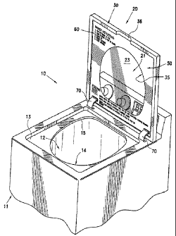
[0016] FIGURE 1 is a fragmentary top perspective view, and
illustrates a washer or dryer, a control panel thereof, and a door or lid in
its
closed position and being defined by a tempered glass panel bordered by an
injection-molded rim, border or encapsulation and upon an inner surface of
the glass panel, one or more coating which provide an opaque peripheral
border of the glass panel and a central viewing area.
[0017 FIGURE 2 is a fragmentary top perspective view, and
illustrates the door/lid in an upper open position thereof, with the
peripheral
border having further a printing medium thereon in the form of instructions
and/or safety rules viewable only when the door is open.
[0018 FIGURE 3 is an enlarged elevational view of the inside of
the door or lid of Figure 2, and illustrates details thereof, including two
openings in each corner of the tempered glass pane! for pivotally or hingedly
connecting the door to the appliance.
[0019, FIGURE 4 is an enlarged fragmentary cross-sectional view
taken generally along line 4-4 of Figure 3; and illustrates details of the
border encapsulating the glass panel and the print media applied thereto and
in part defining the view area of the door.
8
_' '' ..~ '. '. .. : 'CA 02473769 2004-07-12_ ~ .
[0020) FIGURE 5 is a fragmentary top-perspective view, and
illustrates another appliance and a door pivotally connected thereto.
(0021 FIGURE 6 is a fragmentary enlarged cross-sectional view
taken generally along line 6-6 of Figure 5, and illustrates a forward finger
grip area of the encapsulation and a sealing or seating channel thereof of a
concave configuration seating upon a convex seating or sealing peripheral
wall outboard of an opening of the appliance cabinet.
[0022] FIGURE 7 is an enlarged fragmentary cross-sectional view
taken generally along fine 7-7 of Figure 5, and illustrates the cooperative
seating of sides of the border and the cabinet convex seating opposite those
shown in Figure 5.
DETAILED DESCRIPTION OF THE INVENTION
[0023 A novel "white" appliance constructed in accordance with
this invention is illustrated in Figures 1 and 2 of the drawings and is
generally designated by the reference numeral 10. The "white" appliance 10
is a washer or dryer and includes a conventional cabinet or body 11 having
an interior chamber, compartment, drum or tub 12 which at its top is closed
by a conventional top wall 13 having an opening 14 defined by a peripheral
edge 15. The opening 14 can be of a variety of different sizes and shapes
but must be sufficiently large to permit clothing to be easily deposited in or
withdrawn from the compartment 12. A control panel 16 forms no part of
the invention and is of a conventional construction, including all necessary
dials, touch panels, etc. to control the operation of the washer or dryer 10.
[~0243 A washer or dryer lid or door 20 constructed in accordance
with this invention includes a tempered glass pane9 21 (Figure 4) of a
9
~ , . , ~ 02473769 2004 07,-12
predetermined peripheral configuration defined by a substantially continuous
peripheral edge 22. The tempered glass panel 21 further includes opposite
inner and outer surfaces 23, 24, respectively, bridged by the peripheral edge
22. A substantially polygonal, rectangular or square peripheral portion 25 of
the tempered glass pane( 21 is defined by the peripheral edge 22 and
immediately adjacent surface portions of the opposite inner and outer
surfaces 23, 24, respectively.
[0025] An open frame-like rim, border or encapsulation 30 is
formed as a one-piece injection molding of polymeric/copolymeric synthetic
plastic material, has a refative(y minor cross-section and is unitized to a
vary
minor peripheral area of the peripheral edge portion 25 of the tempered
glass pane! 21 (Figures 3 and 4).
[0026] The open frame-like encapsulation 30 includes an outer
peripheral portion 31 (Figure 4), an inner peripheral portion 33 and an outer
peripheral portion 34 respectively adjacent the surfaces 23, 24 at the
peripheral edge portion 25 of the tempered glass panel 21. Though the
encapsulation 30 is injection molded upon the peripheral edge portion 25 of
the tempered glass panel 21, such is not done until the inner surface 23 of
the tempered glass panel 21 has applied thereto, preferably by stencil
screen printing, a first printing medium 40, a second printing medium 50 and
a third printing medium 60, all of which are preferably a ceramic printing
medium heat fusible at approximately 800 F. or above.
[0027, The printing medium 40 ranges between substantially
translucent to substantially opaque and is preferably substantially opaque
and might be, for example, white if the overall color of the appliance 10 is
white. The printing medium 40 defines a relatively narrow peripheral border
CA 02473769 2004-07-12 y
having an outermost peripheral edge 41 (Figure 4) which corresponds to the
peripheral edge 22 of the tempered glass panel 21 and an innermost or
inboard edge 42 defining a translucent central view area 35 which, of course,
corresponds in size and shape to the opening 12 defined by the edge 15 and
the top panel 13 of the appliance 10.
(0028 After the printing medium 40 has sufficiently cooled, the
second printing medium 50 is overcoated thereupon, preferably by screen
printing, either completely or decoratively in a manner which, when viewed
from above in the closed position of the door 20 (Figure 1) imparts a
variation in tone or shade or translucence to the coatings 40, 50. As an
example, the printing medium 50 can be applied upon the printing medium
40 in the form of substantially very opaque and very closely adjacent
crossing lines, much in the manner of insect screening for doors and
windows which, after fusion and cooling, appears from above as a series of
very closely adjacent very opaque crossing fines against the continuous
unbroken coating of the somewhat lesser opaque printing medium 40
thereby creating a regular "mottled" or "dotted" appearance even if the
printing media are both white, namely, white-on-white. The printing
medium 50 also includes an outboard or outermost peripheral edge 51
(Figure 4) contiguous the edge 41 of the printing medium 40 and an
innermost or inboard edge 52 which is contiguous the edge 42 of the
printing medium 40 and defines therewith the translucent central viewing
area 35 which, once again, corresponds to the opening I4 of the top panel
13 defined by the edge 15 thereof (Figure 2). The printing media 60 is
preferably any one or both of °'WASHER INSTRUCTIONS" and "PERSONAL
SAFETY RULES," as is reflected best in Figure 3 of the drawings, with the
11
CA 02473769 2004 07 12.. ' -.
lower unnumbered portion of the printing media 50 being of a sufficient size
to accommodate the desired language, as is reflected by the three sentences
each beginning "NEVER." The "WASHER INSTRUC?'IONS" of the printing
media 60 are more succinct and can be readily accommodated upon a corner
portion (unnumbered) of the printing media 50. Obviously, the color of the
printing media 60 is in contrast to that of the printing media 50 and/or 40,
such as black which is readily visible against the white printing medium 50,
but only when, the door 20 is open (Figures 2 and 3).
[0029] It is only after the printing medium 60 has been fused and
cooled that the tempered glass panel 21 with the fused printing media 40,
50, 60 thereon is placed in a mold and the border 30 is injection molded
thereon fusing to the peripheral edge'portion 25 of the tempered glass panel
21 and the edges 41, 51, as well as to an adjacent peripheral surface
(unnumbered) of the printing medium 50.
[0030] As is most readily apparent from i=figure 1 of the drawings,
in the closed position of the door 20, the medium 60 is totally indiscernible,
yet is upright and readable upon the door 20 being opened (Fi.gures 2 and
3), whether by means of upward pivoting movement (Figure 1 to Figure 2)
or pivoting about a vertical axis (not shown) when the door 20 is associated
with a front-loading washer or dryer (not shown). Since the border 30 is
relatively narrow, a minor hand grip area or recess 36 is provided at a side
thereof remote from metal hinges 70, 70 (Figure 2) which are substantially
identical and each includes bifurcated ends (not shown) which are introduced
into pairs of openings 7i, 71 at each of two corners of the tempered glass
panel 2i and are adhesively bonded thereto by high strength glass-to-metal -
12
~~ 02473769 2004-07-12 ' ,
adhesive 73 which corresponds in color to the printing medium 40 and the
border 30, which is preferably white.
[0033.] From the foregoing, an extremely uncomplicated two-piece
appliance door 20 is provided which is aesthetic, yet fulfills all necessary
criteria including the presence of "INSTRUCTIONS/C~AFETY RULES" 60 visible
only when the door 20 is open (Figures 2 and 3) and totally invisible when
the door 20 is closed (Figure ~.).
[0032] Another appliance constructed in <~ccordance with this
invention is illustrated in Figures 5 through 7 of the drawings and is
generally designated by the reference numeral 10'. Primed reference
characters have been applied to the appliance 10' to indicate structure
identical to that of the appliance 10. The appliance i0' differs from the
appliance 10 in two basic features, namely, in lieu o~f the finger grip recess
35 of the border 30 of the appliance 10, a border 30' of the appliance 10'
has a front edge 80 which projects downwardly and outwardly (Figure 6)
beyond a front wall (unnumbered) of a cabinet li' t:o permit a door 20' to be
grasped and manipulated. Secondly, a lower surface of the border 30'
includes a downwardly concavely opening seating arid sealing recess 85
(Figures 6 and 7) which matches and seats upon a c:onvexly upwardly curved
seating or sealing surface 86 of an upper wall 13' of the appliance 10'. The
latter is particularly advantageous when the appliance 10' is a washer
because it provides a continuous peripheral seal to prevent the escape of
water through the opening 14' and beyond the wall 86.
[~033] Each or all of the heat-fusible cer2imic printing medium/
media 40, SO and 60 are preferably conventional ceramic ink/paint which is
a composition of ground glass fragments (frit) pigments (color), flux (used to
13
.. ., x'02473769 2004-07-12 '- - ~ ' .
improve the melting of the frit), and medium (used to create a liquid conditin
for silk screen or similar transfer). Once applied to the glass panel 21
(medium 40) or to each other (media SO and 60), tt~e ink/paint 40, 50, 60
are normally dried to remove the liquid transfer medium leaving a dried film,
decoration, print or the Pike on the glass pane! 21. Some ink/paint/
medium/media are, however, formulated to remain wet up to the firing
and/or tempering process.
[0034] Ceramic heat-fusible ink/paint/medium 40, 50 and/or 60
can be fired (melted) into the surface of the glass panel 21 by careful and
controlled heating followed by careful and controlled cooling to achieve a low
stress/annealed finished product. Tempering is another method to achieve
firing of the ink/paint/media while adding strength to the glass. (Tempered
glass is three to eve times stronger than annealed glass.) Obviously, the
ink/paint/media 40, 50, 60 are formulated to achieve desired color/cofors,
excellent abrasion, and chemical and impact resistance.
[0035] In lieu of the fatter described ceramic heat-fusible medium,
the media 40, 50 and 60 can instead be a urethane adhesive, such as
BETASEAL~ adhesives manufactured by The Dow Chemical Company which
do not require heat, can be applied exclusively cold to the glass panel 21 and
dry within an hour even in temperature extremes (0~ to 115 F.) Typical of
such BEATASEAL~ adhesives are identified under the product numbers 0-
216, 3000HMNC, 1502 HMNC, U-400HV/U-400EP, U-~418HV-U-418EP and 0-
418.
[0036] These adhesives are extremely strong and can also be
utilized as the adhesive 73 for bonding the metal hinges 70, 70 (Figure 2) to
14
_ ' ~ 02473769 2004-07-12 ~ ~ . . -
the pairs of openings 71, 71 at each of the two corners of the tempered
glass panel 21.
[0~37, Although a preferred embodiment of the invention has
been specifically illustrated and described herein, it is to be understood
that
minor variations may be made in the apparatus without departing from the
spirit and scope of the invention, as defined by the appended claims.
IS