Note: Descriptions are shown in the official language in which they were submitted.
CA 02473806 2004-07-20
WO 03/064697 PCT/US03/01061
DEVICE AND METHOD FOR THERMAL CYCLING
Field of the Invention
[01] The present invention relates generally to a thermal cycling device and
method of perForming nucleic acid amplification on a plurality of biological
samples
positioned in a sample well tray. More particularly, the present invention
relates in one
aspect to a thermal cycling device and method of real-time detection of a
nucleic acid
amplification process such as polymerase chain reaction (PCR).
Background
[02] Biological testing has become an important tool in detecting and
monitoring
diseases. In the biological testing field, thermal cycling is used to amplify
nucleic acids
by, for example, performing PCR and other reactions. PCR in particular has
become a
valuable research tool with applications such as cloning, analysis of genetic
expression, DNA sequencing, and drug discovery.
[03] Recent developments in the field have spurred growth in the number of
tests that are performed. One method for increasing the throughput of such
biological
testing is to provide real-time detection capability during thermal cycling.
Real-time
detection increases the efficiency of the biological testing because the
characteristics
of the samples can be detected while the sample well tray remains positioned
in the
thermal cycling device, therefore not requiring removal of the sample well
tray to a
,.
separate area prior to testing of the samples. In typical real-time thermal
cycling
devices, the sample well tray is removed after detection is completed.
SUMMARY OF THE INVENTION
[04] Various aspects of the invention generally relate to a thermal cycling
device
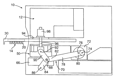
in which the sample block assembly may be vertically moved so that the sample
well
tray may be inserted and removed from the thermal cycling device. The thermal
cycling
CA 02473806 2004-07-20
WO 03/064697 PCT/US03/01061
device can be a real-time device. During such movement of the sample block
assembly and sample well tray, the optical detection system can remain
substantially
stationary.
[05] According to one aspect, the invention comprises a thermal cycling
device.
The thermal cycling device includes a sample block assembly, an optical
detection
system, and a sample well tray holder. The sample well tray holder includes a
tray-
receiving region configured to hold a sample well tray. The optical detection
system is
positioned above the sample block assembly. The sample well tray holder is
configured to translate the sample well tray into alignment with the sample
block
assembly. The sample block assembly is adapted for movement between a first
position permitting the translation of the sample well tray into alignment
with the sample
block assembly, and a second position, upward relative to the first position,
where the
sample block assembly contacts the sample well tray.
[06] In another aspect, the optical detection system is adapted to remain
substantially stationary during insertion and removal of the sample well tray
from the
thermal cycling device. In a further aspect, the thermal cycling device
further includes
a positioning mechanism configured to translate the sample block between the
first and
second positions.
[07] In yet another aspect, the invention comprises a method of performing
nucleic acid amplification on a plurality of biological samples positioned in
a sample
well tray in a thermal cycling device. The method includes the step of placing
the
sample well tray into a sample well tray holder. The method further includes
the step of
translating the sample well tray holder and sample well tray into the thermal
cycling
device until the sample well tray is aligned with a sample block assembly
positioned
beneath the sample well tray. The method further includes the step of
translating the
-2-
CA 02473806 2004-07-20
WO 03/064697 PCT/US03/01061
sample block assembly from a first position to a second position. In the first
position,
the sample block assembly permits the sample well tray to translate into
alignment with
the sample block assembly. In the second position, the sample block assembly
is
positioned vertically upward relative to the first position to contact the
sample well tray.
[08] The method can further comprise the step of thermally cycling the device
while simultaneously optically detecting the samples. The method can further
comprise
translating the sample block assembly from the second position to the first
position.
Finally, the method can comprise the step of removing the sample well tray
holder and
sample well tray from the thermal cycling device. In various embodiments, the
optical
detection system remains substantially stationary throughout the above steps.
[09] In another aspect, the invention comprises a thermal cycling device. The
thermal cycling device includes an optical detection system, a sample block,
and a
sample well tray holder. The sample block is adapted for movement along a
first path,
toward and away from the optical detection system. The sample well tray holder
includes a tray-receiving region. The sample well tray holder is adapted for
movement
along a second path, toward and away from a position whereat the tray-
receiving
region is disposed between the optical detection system and the sample block.
The
optical detection system can be adapted to remain substantially stationary
during
movement of the sample block and the sample well tray holder along the first
and
second paths.
[010] It is to be understood that both the foregoing general description and
the
following detailed description are exemplary and explanatory only and are not
restrictive of the invention, as claimed.
-3-
CA 02473806 2004-07-20
WO 03/064697 PCT/US03/01061
BRIEF DESCRIPTION OF THE DRAWINGS
[011] The accompanying drawings, which are incorporated in and constitute a
part of this specification, illustrate several embodiments of the invention.
In the
drawings,
[012] Fig. 1 is a front view of an exemplary embodiment of a thermal cycling
device according to the present invention;
[013] Fig. 2A is side view of an embodiment of the device of Fig. 1, with a
sample well tray positioned outside of the device;
(014] Fig. 2B is a side view of the device of Fig. 1, with the sample well
tray
inserted into the device;
[015] Fig. 2C is a side view of the device of Fig. 1, with the sample well
tray
inserted into the device and a sample block assembly in an upward position for
engaging the sample well tray;
[016] Fig. 3A is a side view of another embodiment of the thermal cycling
device
of the invention, with a sample well tray positioned outside of the device;
[017] Fig. 3B is a side view of the device of Fig. 3A, with the sample well
tray
inserted into the device;
[018] Fig. 3C is a side view of the device of Fig. 3A, with the sample well
tray
inserted into the device and a sample block assembly in an upward position for
engaging the sample well tray;
[019] Fig. 4A is side view of yet another embodiment of the thermal cycling
device of the invention, with the sample well tray positioned outside of the
device;
[020] Fig. 4B is a side view of the device of Fig. 4A, with the sample well
tray
inserted into the device;
-4-
CA 02473806 2004-07-20
WO 03/064697 PCT/US03/01061
[021 ] Fig. 4C is a side view of the device of Fig. 4A, with the sample well
tray
inserted into the device and a sample block assembly in an upward position for
engaging the sample well tray;
[022] Fig. 5 is a side cross sectional view of a sample well tray holder, used
with
the present invention, with a sample well tray positioned thereon; and
[023] Fig. 6 is a perspective view of one embodiment of a sample block
assembly used in the device of the invention.
DESCRIPTION OF CERTAIN EMBODIMENTS
[024] Reference will now be made to certain exemplary embodiments of the
invention, examples of which are illustrated in the accompanying drawings.
Wherever
possible, the same reference numbers are used in the drawings and the
description to
refer to the same or like parts.
[025] In accordance with certain embodiments, a thermal cycling device is
provided. In one aspect, the thermal cycling device may perform nucleic acid
amplification on a plurality of biological samples positioned in a sample well
tray. In
certain embodiments, the thermal cycling device includes a sample block
assembly, an
optical detection system positioned above the sample block assembly, and a
sample
well tray holder with a tray-receiving region configured to hold the sample
well tray. In
certain aspects, the sample block assembly is adapted for movement between a
first
position permitting the translation of the sample well tray into alignment
with the sample
block assembly, and a second position, upward relative to the first position,
where the
sample block assembly contacts the sample well tray. The thermal cycling
device may
also include a positioning mechanism for translating the sample block between
the first
and second positions.
-5-
CA 02473806 2004-07-20
WO 03/064697 PCT/US03/01061
[026] Although the terms "horizontal," "vertical," "upward," and "downward"
are
used in describing various aspects of the present invention, it should be
understood
that such terms are for purposes more easily describing the invention, and do
not limit
the scope of the invention.
[027] In various embodiments, such as illustrated in Figs. 1, 2A-2C, and 5-6,
the
thermal cycling device 10 for performing nucleic acid amplification on a
plurality of
biological samples includes one or more of: a sample block assembly 50; an
optical
detection system 12 for detecting the characteristics of the samples
positioned in a
sample well tray 14; a sample well tray holder 30; and a positioning mechanism
70
connected to the sample block assembly, the positioning mechanism being
configured
to impart vertical movement on the sample block assembly.
[028] The thermal cycling device is typically configured to perform nucleic
acid
amplification. One common method of performing nucleic acid amplification of
biological samples is polymerase chain reaction (PCR). Various PCR methods are
known in the art, as described in, for example, U.S. Patent Nos. 5,928,907 and
6,015,674 to Woudenberg et al., the complete disclosures of which are hereby
incorporated by reference for any purpose. Other methods of nucleic acid
amplification
include, for example, ligase chain reaction, oligonucleotide litigations
assay, and
hybridization assay. These and other methods are described in greater detail
in U.S.
Patent Nos. 5,928,907 and 6,015,674.
[029] In one embodiment, the thermal cycling device performs real-time
detection of the nucleic acid amplification of the samples during thermal
cycling. Real-
time detection systems are known in the art, as also described in greater
detail in, for
example, U.S. Patent Nos. 5,928,907 and 6,015,674 to Woudenberg et al.,
incorporated herein above. During real-time detection, various characteristics
of the
-6-
CA 02473806 2004-07-20
WO 03/064697 PCT/US03/01061
samples are detected during the thermal cycling in a manner known in the art.
Real-
time detection permits more accurate and efficient detection and monitoring of
the
samples during the nucleic acid amplification.
[030] In accordance with various embodiments, the thermal cycling device
includes an optical detection system. As embodied herein and shown in Figs. 1
and
2A-2C, an optical detection system 12 is positioned above the sample block
assembly
50. The optical detection system 12 is configured to detect and monitor the
characteristics of the samples in the sample well tray 14 in real-time during
the thermal
cycling. Suitable structures and methods for the optical detection system 12
are well
known in the art. The optical detection system may use any known structure or
method. In one example, the optical detection system would include a quartz
bulb with
a CCD camera, in a manner known in the art. In another example, the optical
detection
system may include a fluorescence based system with a lens and a fiber optics
for
each cable as described in U.S. Patent Nos. 5,928,907 and 6,015,674 to
Woudenberg
et al, incorporated herein above. Alternatively, the optical detection system
may
include any known system using a single light source for each sample well, in
a manner
known in the art. Likewise, the optical detection system may include any other
type
suitable for use with the thermal cycling device of the present invention.
(031] In various embodiments, optical detection system 12 is substantially
stationarily mounted in the thermal cycling device. The optical detection
system can be
configured so that the optical detection system remains substantially
stationary during
insertion of a sample well tray holder and sample well tray into the thermal
cycling
device, during thermal cycling of the sample well tray, during removal of the
sample
well tray holder and sample well tray from the thermal cycling device, and at
all stages
in between the above steps. By remaining substantially stationary, the optical
system
_7_
CA 02473806 2004-07-20
WO 03/064697 PCT/US03/01061
reduces the potential for misalignment of the optical components. For purposes
of this
invention, the term "substantially stationary" does not mean that the optical
detection
system is completely stationary, rather, the term includes any vibrations or
movements
caused by normal operation of the thermal cycling device.
[032] The thermal cycling device may be configured for use with any type of
sample well tray, including, for example, 96-well sample well trays, 384-well
sample
trays, and microcard sample trays. The size and shape of these sample well
trays are
well known in the art. Examples of 96-well sample well trays.suitable for use
in the
present invention are described in WO 00/25922 to Moring et al., the complete
disclosure of which is hereby incorporated by reference for any purpose.
Examples of
sample well trays of the microcard type suitable for use in the present
invention are
described in WO 01/28684 to Frye et al., the complete disclosure of which is
hereby
incorporated by reference for any purpose, WO97/36681 to Woudenberg et al.,
the
complete disclosure of which is hereby incorporated by reference for any
purpose, U.S.
Application Serial No. 09/897,500, filed July 3, 2001, assigned to the
assignee of the
present invention, the complete disclosure of which is hereby incorporated by
reference
for any purpose, and U.S. Application Serial No. 09/977,225, filed October 16,
2001,
assigned to the assignee of the present application, the complete disclosure
of which is
hereby incorporated by reference for any purpose. Sample well trays having any
number of sample wells and sample well sizes may also be used with the thermal
cycling device of the present invention. In the example shown in the figures,
the
volume of the sample wells may vary anywhere from about 0.01 p,l to thousands
of
microliters (~,I), with a volume between 10 to 500 ~.I being typical.
[033] As embodied herein and shown in Figs. 1, 2A-2C, and 5, the sample well
tray 14 can include a rectangular top portion 16 having a top surface 18 and
bottom
_g_
CA 02473806 2004-07-20
WO 03/064697 PCT/US03/01061
surface 24. The top surface 18 defines openings for a plurality of sample
wells 20 of
any known size and shape. In the example shown in Figs. 1-6, the sample well
tray
includes ninety-six sample wells positioned in a well-known 8. x 12 array. In
the
embodiment shown, the top portion 16 of the sample well tray is rectangular.
In the
embodiment shown in the figures, the sample wells are conical shape recesses
extending downwardly from the top surface 18 in a known manner. Each sample
well
includes a sample well bottom surface 22 for engaging with corresponding
recesses in
the sample block assembly 50. It is well understood that any type of sample
well
configuration may be used with the present invention, including for example, a
3~4-well
sample well tray and a microcard type sample tray.
[034] In accordance with various embodiments, the thermal cycling device can
include a sample well tray holder having a tray-receiving region configured to
hold the
sample well tray. The sample well tray holder can be configured to translate
the
sample well tray into alignment with a sample block assembly. As described
herein
and shown in Figs. 1, 2A-2C, and 5, the sample well tray holder is generally
designated
by reference number 30. The sample well tray holder is configured so that the
sample
well tray may be supported thereon, particularly during insertion of the
sample well tray
into the thermal cycling device, and during removal of the sample well tray
from the
thermal cycling device. In various embodiments, the sample~well tray holder 30
is
generally rectangular in shape.
[035] With particular reference to Fig. 5, the sample well tray holder 30
includes
a top surface 32 and a side surface 34 that extends around the periphery of
the sample
well tray holder. The side surface in the front of the device is designated by
reference
number 36. The sample well tray holder further includes a tray-receiving
region
configured to hold a sample well tray. In the embodiment shown in Fig. 5, the
tray-
_g_
CA 02473806 2004-07-20
WO 03/064697 PCT/US03/01061
receiving region is defined by a downwardly projecting holder structure 38 in
the top
surface 32. The downwardly projecting holder structure 38 is positioned on a
first
recessed portion 40 of the top surface 32. The downwardly projecting holder
structure
38 includes a horizontally projecting annular projection 42 for engaging the
top surface
of the first recessed portion 40 of the top surface 32. The downwardly
projecting holder
structure 38 further comprises a projection 44 that slopes inwardly. The
inside of the
projection 44 defines a rectangular opening or recess slightly smaller than
the sample
well tray 16. The rectangular opening or recess is dimensioned to receive a
sample
well tray. In particular, the projection 44 is dimensioned so that the bottom
surface 24
of the sample well tray may rest on the top surface of the projection 44, as
shown in
Fig. 5. The projecting holder structure may be shaped to be angled inwardly in
order to
ease the removal of the sample well tray from the sample well tray holder.
[036] The sample well tray holder 30 and sample well tray 14 are dimensioned
so that they are capable of passing between the optical detection system 12
and the
sample block assembly 50 without interference during insertion into and
removal from
the thermal cycling device. The sample well tray is configured so that it can
horizontally translate into and out of the thermal cycling device on the
sample well tray
holder. In order to facilitate insertion or removal of the sample well tray
holder, bearing
surfaces (not shown) may be provided on the sample well tray holder and/or
thermal
cycling device. The sample well tray holder may be horizontally translated
either
manually or automatically.
[037] In accordance with various embodiments, the thermal cycling device can
include a sample block assembly configured to receive the sample well tray
thereon.
As described herein and shown in Figs. 1, 2A-2C, 5, and 6, a sample block
assembly is
generally designated by reference number 50. It is to be understood that the
sample
-10-
CA 02473806 2004-07-20
WO 03/064697 PCT/US03/01061
block assembly shown in Fig. 6 is by way of example only, and the invention is
not
limited to the sample block assembly shown in Fig. 6. The sample block
assembly
shown in Fig. 6 includes a sample block 58 and a heat sink 56. Sample blocks
are well
known in the art. Sample blocks may be made of any suitable material, such as
aluminum. The sample block assembly typically includes at least one heating
element.
In one embodiment, the at least one heating element includes a pettier heater.
Methods of heating and cooling a sample block during and after thermal cycling
are
known in the art. The sample block 58 shown in Fig. 6 includes a top surface
54 with a
plurality of recess 52 on the top surface. The recesses are arranged to
correspond to
the sample wells of the sample well tray. For example, in the embodiment shown
in
Fig. 6, the sample block assembly includes ninety-six recesses for engaging
with a 96-
well sample well tray. Alternatively, the sample block assembly can have any
number
of recesses. For example, the number of recesses can equal the number of
sample
wells. In an embodiment with a 384-well sample tray, the sample block assembly
would typically have at least 384 recesses. In an embodiment using a microcard
type
sample tray, the sample block need not have recesses.
[038] Heat sink 56 may be any known type of heat sink. Additionally, a
convection unit such as a fan may be positioned adjacent the sample block
assembly.
In the embodiment shown in Figs. 1, 2A-2C, and 5-6, the convection unit
comprises a
fan 66 positioned below the sample block assembly 50. In one embodiment, the
fan 66
creates a flow of cooling air against the heat sink 56 in order to cool the
sample block.
Alternatively, the fan may be used with a heater in order to create a flow of
hot air
against the heat sink in order to heat the sample block. In certain
embodiments, the
fan is mounted so that it moves vertically with the sample block assembly. In
other
embodiments, the fan may be stationarily mounted in the thermal cycling device
-11-
CA 02473806 2004-07-20
WO 03/064697 PCT/US03/01061
[039] In accordance with various embodiments, the thermal cycling device can
include a positioning mechanism connected to the sample block assembly, the
positioning mechanism being configured to vertically translate the sample
block
assembly between a first or "downward" position and a second or "upward"
position.
The positioning mechanism can be configured to translate the sample block
assembly
between the first position, where the sample block assembly permits the
translation of
the sample well tray into alignment with the sample block assembly, and the
second
position, upward relative to the first position, where the sample block
assembly
contacts the sample well tray.
[040] An embodiment of the positioning mechanism is illustrated in Figs. 1 and
2A-2C. In the embodiment shown in Figs. 1 and 2A-2C, the positioning mechanism
is
generally designated by reference number 70. The positioning mechanism is
connected to the sample block assembly 50. The positioning mechanism allows
insertion and removal of the sample well tray by moving the sample block
assembly in
the vertical direction. Figs. 2A and 2B show the downward or "first" position
of the
sample block assembly. In the downward position, a gap is created between the
top of
the sample block assembly 50 and a bottom portion 94 of the optical detection
system
of sufficient size so that the sample well tray holder and sample well tray
may be
inserted therebetween. In the first position, the sample block is "away" from
the optical
detection system.
[041] In a second or "upward" position shown in Fig. 2C, the sample block
assembly 50 is vertically upward relative to the downward or "first" position.
In the
upward position, the top surface 54 of the sample block 58 presses against the
bottom
of the sample well tray 14 so that the recesses 52 mate with the sample well
bottom
surfaces 22. In various embodiments using a microcard, a top surface of the
sample
-12-
CA 02473806 2004-07-20
WO 03/064697 PCT/US03/01061
block can press against a bottom surface of the microcard. In the second
position, the
sample block is "toward" the optical detection system. The sample block
assembly is
adapted for movement toward and away from the optical detection system along a
predetermined vertical path.
[042] In the embodiment shown in Figs. 1 and 2A-2C, the positioning
mechanism 70 includes a plurality of links. The arrangement of links shown in
Figs. 1
and 2A-2C is by way of example only. The plurality of links includes a first
link 78 as
shown in Figs. 2A-2C. The first link 78 is shown as being in the shape of a
connecting
rod, however, the first link may have any number of different shapes. First
link 78
includes a first end 80 rotatably connected to a motor 72 at a pivot point 74.
Motor 72
can be any known type of motor that is capable of imparting a translational or
rotational
force on the first link 78. As shown in Figs. 2A-2C, the motor causes pivot
point 74 of
the first end 80 to revolve around a central axis 76 of the motor. The
revolution of the
first end 80 about the central axis of the motor causes the first link to
translate.
[043] As shown in Figs. 2A-2C, a second end 82 of the first link is rotatably
connected to a first end of a second link 84 at pivot point 88. The second
link has a
second end rotatably connected to stationary pivot point 86. The second link
84 pivots
about stationary pivot point 86 when the motor causes movement of the first
link 78.
[044] The second end 82 of the first link is rotatably connected to a first
end of a
third link 90 at pivot point 88. The second end of the third link 90 is
rotatably connected
to the sample block assembly at pivot point 92. By revolution of the first end
of the first
link about the central axis 76 of the motor, the first link causes the first
end of the
second link 84 to rotate partially about the stationary pivot point 86, thus
causing the
third link to press upward against the sample block assembly at pivot point
92. The
positioning mechanism is connected to the sample block assembly by, for
example, a
-13-
CA 02473806 2004-07-20
WO 03/064697 PCT/US03/01061
pin at pivot point 92. As a result of this linkage arrangement, the
positioning
mechanism causes the sample block assembly to move vertically from the
downward
or "first" position shown in Figs. 2A and 2B to the upward or "second"
position shown in
Fig. 2C. It should be understood that the positioning mechanism of Figs. 2A-2C
is by
way of example only.
[045] As shown in Fig. 1, the positioning mechanism 70 may include two sets of
links, one on each lateral side of the sample block assembly. The second set
of links is
a mirror image of the first set of links. In Fig. 1, the second set of links
includes first link
(not shown), second link 84', and third link 90'. With a configuration having
two sets of
links, an individual motor may be utilized for each of the sets of links, or
alternatively, a
single motor may be utilized for both sets of links. In another variation, a
single set of
links may be used instead of two sets of links. In a further variation, more
than two
sets of links may be used.
[046] The positioning mechanism may also include at least one guide member
for guiding the sample block assembly in the vertical direction. The guide
member can
be configured to prevent the sample block assembly from moving in the
horizontal
direction. Any known type of guide member may be utilized. In the embodiment
shown in Figs. 1 and 2A-2C, the guide member includes a plurality of vertical
shafts 96
fixedly attached to the lateral sides of the sample block assembly 50. As
shown in Fig.
1, the vertical shafts are positioned on each lateral side of the sample well
tray holder
30 and sample well tray 14. Each vertical shaft 96 is received within bearing
member
98. Bearing member is stationarily mounted adjacent the optical detection
system.
Each vertical shaft 96 slides within a corresponding cylindrical opening in
the bearing
member 98. The bearing members 98 and vertical shafts 96 may include any type
of
known bearing arrangement. . ,
-14-
CA 02473806 2004-07-20
WO 03/064697 PCT/US03/01061
[047] Alternatively, in another variation, the vertical shaft could be
stationarily
fixed to fihe thermal cycling device so that the sample block assembly
translates
vertically relative to the vertical shaft. With such an arrangement, the
bearing
structures would be mounted within cylindrical openings in the sample block
assembly
for receiving the vertical shafts.
[048] The guide member may be any other type of known guide member
capable of limiting movement of the sample block assembly in the horizontal
direction
as the sample block assembly is moved in the vertical direction. For example,
the
guide member could include any type of vertical guiding structure adjacent the
sample
block assembly. It should be understood that the guide member shown in Figs.
2A-2C
is by way of example only.
[049] An operation of the thermal cycling device for the embodiment of Figs. 1
and 2A-2C is further described below. First, with the sample well tray holder
30 in an
outward position as shown in Fig. 2A, a sample well tray 14 is placed in the
sample well
tray holder. The sample well tray can be dropped into the recess defined by
downwardly projecting holder structure 38 shown in Fig. 5. The sample well
tray 14
may be placed in the sample well tray holder 30 either manually or
robotically.
[050] In Fig. 2A, the sample block assembly 50 is in a downward or "first"
position so that a gap is created between the optical detection system 12 and
the
uppermost surface of the sample block 58. The gap that is created is larger
than the
vertical dimension of the sample well tray holder 30 and sample well tray 14.
[051 ] After the sample well tray 14 is placed in the sample well tray holder
30,
the sample well tray holder is horizontally translated into the thermal
cycling device 10
until the sample well tray reaches a position where the sample wells of the
sample well
tray align with the recesses 52 of the sample block 58. The horizontal
translation may
-15-
CA 02473806 2004-07-20
WO 03/064697 PCT/US03/01061
be caused by an operator or a robot pressing on the sample well tray. In the
embodiment shown in Figs. 1 and 2A-2C, the sample well tray holder 30 can be
horizontally translated until each of the ninety-six sample wells align with a
corresponding recess 52 in the sample block 58. Fig. 2B shows the sample well
tray
holder 30 and sample well tray 14 in the position where the sample wells 20
are aligned
with corresponding recesses in the sample block 58. As shown in Fig. 2B, the
sample
block assembly 50 can remain in the downward position until. the sample well
tray is
fully inserted into the thermal cycling device and aligned.
[052] After the sample well tray 14 has been fully inserted into the thermal
cycling device 10 and proper alignment has been achieved between the sample
wells
20 and the recesses 52 of the sample block (as shown in Fig. 2B), the motor 72
can be
actuated to begin a revolution of the first end 80 of the first link 78. As
the first end 80
of the first link 78 begins to revolve around the central axis 76 of the
motor, the pivot
point 88 is moved leftward as shown in Fig. 2G, and the pivot point 92 of the
second
end of the third link imparts an upward force on the sample block assembly 50.
As a
result, the sample block assembly 50 is moved upward so that the top surface
54 of the
sample block firmly contacts the bottom surface of the sample well tray 14. In
the
upward position (also referred to as the "second position") shown in Fig. 2C,
the
sample block assembly 50 is firmly positioned against the sample well tray 14
so that
the sample wells 22 are seated against the sample block. The thermal cycling
device
is now ready for thermal cycling processes.
[053] At any desired time, e.g., after the thermal cycling processes are
completed, the sample well tray 14 can be removed by actuating the motor so
that the
sample block assembly 50 moves to a downward position (as shown in Fig. 2B),
and
then horizontally translafiing the sample well tray holder 30 and sample well
tray 14 to
-16-
CA 02473806 2004-07-20
WO 03/064697 PCT/US03/01061
the position shown in Fig. 2A. The sample well tray 14 may then be removed
from the
sample well tray holder 30.
[054] The amount of vertical displacement of the sample block assembly 50
between the downward ("first") and upward ("second") positions depends on the
specific application, the type and size of sample well tray that is utilized,
and other
practical concerns. For example, in an application for use with a 96-well
sample well
tray, the amount of vertical displacement would typically be between about 0.5
to 1.5
inches, but it could be much greater or much less. In an application with a
384-well
sample tray having smaller sample wells, or a microcard, the amount of
vertical
displacement of the sample block assembly may be less. For practical purposes
however, it may also be desirable to vertically displace the sample block
assembly a
much greater distance in order to provide better access to the inside of the
device for
inspection or maintenance.
[055] In accordance with various embodiments, the optical detection system 12
can be mounted in a substantially stationary manner in the thermal cycling
device
during insertion and removal of the sample well tray to and from the thermal
cycling
device, during thermal cycling, and during all steps therebetween.
[056] In accordance with further various embodiments of the positioning
mechanism, the plurality of links comprises a first link and a second link.
The first link
has a first end rotatably connected to a stationary pivot point. The first
link also has a
second end comprising a handle for manual manipulation of the first link. The
second
link has a first end rotatably connected to a pivot point on the first link.
The second link
also has a second end rotatably connected to the sample block assembly.
[057] Further various embodiments of the sample block assembly positioning
mechanism contemplate structure such as shown in Figs. 3A-3C. The positioning
17-
CA 02473806 2004-07-20
WO 03/064697 PCT/US03/01061
mechanism is generally designated by the reference number 100 in Figs. 3A-3C.
The
positioning mechanism includes a plurality of links such as first link 102 and
second link
104. As shown in Fig. 3A, the first link 102 has a first end rotatably
connected to a
stationary pivot point 106 and a second end defining a handle 108 for manual
manipulation of the first link. In Figs. 3A-3C, the first link 102 is in the
shape of a
connecting rod with a bend as shown in Fig. 3A. The handle 108 of the first
link 102
defines a door 112 corresponding to an opening 114 in the thermal cycling
device. The
door 112 is configured to cover the opening 114 in the thermal cycling device
when the
handle is actuated in a manner described below. Although the door is shown
having
an arcuate shape on the inner surface, any other suitable shape is also
acceptable.
[058] As shown in Fig. 3A, the second link 104 has a first end rotatably
connected to a pivot point 118 positioned on first link 102. The second link
104 has a
second end rotatably connected to the sample block assembly 50 at pivot point
120.
By the linkage arrangement described above, the actuation of the handle 108
will
cause the sample block assembly 50 to translate in the vertical direction.
[059] An operation of the thermal cycling device for the embodiment of Figs.
3A-
3C will be briefly described below. To the extent that the following operation
is similar
to the operation described above for the embodiment shown in Figs. 1 and 2A-
2C, a
detailed description of the operation will not be repeated. Moreover, the same
reference numbers will be used to refer to the same or like parts as shown in
the
embodiment of Figs. 1 and 2A-2C. Fig. 3A shows the sample well tray holder 30
and
sample well tray 14 in an outward position. In Fig. 3A, the sample block
assembly 50 is
in the downward or "first" position. The sample well tray holder 30 is then
inserted into
the thermal cycling device 10 by translating in the horizontal direction until
the sample
-18-
CA 02473806 2004-07-20
WO 03/064697 PCT/US03/01061
well tray 14 reaches its proper aligned position (shown in Fig. 3B) between
the optical
detection system and the sample block assembly.
[060] After the sample well tray 14 reaches its aligned position, an operator
may
manually press against the handle 108 to rotate the first link 102 about the
stationary
pivot point 106. In another embodiment, the handle may be rotated robotically.
In
either case, the clockwise rotation (in reference to Figs. 3A-3C) of the first
link 102
results in the pivot point 118 moving upward, thereby causing the pivot point
120 on the
second link 104 to move upward. The upward movement of the second link results
in
translation of the sample block assembly 50 in an upward vertical direction to
an
upward or "second" position (shown in Fig. 3C). The positioning mechanism is
configured so that the door 112 is fully closed as shown in Fig. 3C when the
top
surface of the sample block firmly contacts the sample well tray. When the
sample
block assembly is in the upward position, as shown in Fig. 3C, the thermal
cycling
device is ready for thermal cycling processes.
[061] At any desired time, e.g., upon completion of the thermal cycling
processes, the handle 108 may be rotated counterclockwise, thereby translating
the
sample block assembly 50 back to the downward position shown in Fig. 3B. The
sample well tray holder can then be slid from the thermal cycling device and
returned to
the position shown in Fig. 3A, and the sample well tray 14 may be removed from
the
sample well tray holder.
[062] In accordance with still further embodiments of the positioning
mechanism, the plurality of links can comprise a first link and a second link.
The first
link is rotatably connected to a stationary pivot point. The first link has a
first end
rotatably connected to the second link and a second end comprising a handle
for
manual manipulation of the first link. The second link has a first end
rotatably
-19-
CA 02473806 2004-07-20
WO 03/064697 PCT/US03/01061
connected to the first end of the first link and a second end rotatably
connected to the
sample block assembly.
[063] Such embodiments of the positioning mechanism include that shown in
Figs. 4A-4C. As shown in Figs. 4A-4C, the positioning mechanism is generally
designated by reference number 130. The positioning mechanism 130 includes a
plurality of links such as first link 132 and second link 134. As shown in
Fig. 4A-4C, the
first link 132 is rotatably connected to a stationary pivot point 136. The
first link 132
has a first end rotatably connected to the second link 134 at a pivot point
138. The first
link includes a second end comprising a handle 140 for manual or automatic
manipulation of the first link 132. The second link 134 includes a first end
rotatably
connected to the first end of the first fink at pivot point 138. The second
link 134 further
includes a second end rotatably connected to the sample block assembly 50 at
pivot
point 142.
[064] As shown in Figs. 4A-4C, the first link 132 includes a first segment 144
and a second segment 146. In Figs. 4A-4C, the first segment 144 and second
segment 146 of the first link are substantially perpendicular to each other.
This angle is
by way of example only, as the linkages may have various configurations. By
the
linkage arrangement described above, the actuation of the handle 140 will
cause the
sample block assembly to translate in the vertical direction.
[065] An operation of the thermal cycling device for the positioning mechanism
of Figs. 4A-4C will be briefly described below. To the extent that the
following
operation is similar to the operation for the other embodiments described
above, a
detailed description of the operation will not be repeated. Fig. 4A shows the
sample
well tray holder 30 and sample well tray 14 in an outward position. In Fig.
4A, the
sample block assembly 50 is in the downward or "first" position. The sample
well tray
-20-
CA 02473806 2004-07-20
WO 03/064697 PCT/US03/01061
holder 30 is then inserted into the thermal cycling device 10 by translating
in the
horizontal direction until the sample well tray reaches its proper aligned
position (shown
in Fig. 4B).
[066] After the sample well tray reaches its aligned position, an operator may
manually or automatically press downward against the handle 140 to rotate the
first link
132 about the stationary pivot point 136 in a counterclockwise direction (in
reference to
Figs. 4A-4C). This counterclockwise rotation of the first link 132 results in
the pivot
point 138 moving upwardly thereby causing the second link 134 to move
upwardly.
The upward movement of the second link results in translation of the sample
block
assembly 50 in an upward vertical direction to an upward or "second" position.
Fig. 4C
shows the sample block assembly in the upward or "second" position. When the
sample block assembly is in the upward position, as shown in Fig. 4C, the
thermal
cycling device is ready for thermal cycling processes.
[067] At any desired time, e.g., upon completion of the thermal cycling
processes, the handle 104 may be rotated clockwise, thereby translating the
sample
block assembly 50 back to the downward position as shown in Fig. 4B. The
sample
well tray holder 30 can then be slid from the thermal cycling device and
returned to the
position shown in Fig. 4A, and the sample well tray 14 may be removed from the
sample well tray holder.
[068]q The sample block assembly positioning mechanisms shown in the figures
are provided for purposes of example only. Other positioning mechanisms could
be,
for example, a hydraulic, a spring, a lever, a cam, a solenoid, or any other
suitable
motion-producing device.
[069] As is clear from the above description, the present invention includes a
method of performing nucleic acid amplification on a plurality of biological
samples
-21 -
CA 02473806 2004-07-20
WO 03/064697 PCT/US03/01061
positioned in a sample well tray in a thermal cycling device. The method
includes the
step of placing the sample well tray into a sample well tray holder. The
sample well
tray 14 shown in the figures is configured for placement into a corresponding
recess in
the sample well tray holder 30.
[070] The method further includes the step of translating the sample well tray
holder and sample well tray into the thermal cycling device until the sample
well tray is
aligned with a sample block assembly positioned beneath the sample well tray.
In one
aspect, the translation of the sample well tray holder is in the horizontal
direction. The
aligned position is shown for example in Fig. 2B. The method further includes
the step
of translating the sample block assembly from a first position to a second
position. In
one aspect, the translation of the sample block assembly is in the vertical
direction. In
the first position, the sample block assembly permits the sample well tray to
translate
into alignment with the sample block assembly. The first position of the
sample block
assembly 50 is shown for example in Fig. 2B. In the second position, the
sample block
assembly is positioned vertically upward relative to the first position in
order to contact
the sample block assembly to the sample well tray. The second position of the
sample
block assembly 50 is shown for example in Fig. 2C.
[071] The method further comprises thermally cycling the device while
simultaneously optically detecting the samples. An optical detection system 12
is
positioned within the thermal cycling device 10 for detecting the
characteristics of the
sample. The method further comprises translating the sample block assembly
from the
second position to the first position. Finally, the method comprises the step
of
removing the sample well tray from the thermal cycling device. The optical
detection
system remains substantially stationary throughout the above steps.
-22-
CA 02473806 2004-07-20
WO 03/064697 PCT/US03/01061
[072] It is clear that the present invention is not limited to the examples
shown.
For example, a thermal cycling device could be configured to handle several
sample
well trays, e.g., positioned side by side. Such an arrangement could include a
corresponding optical system and sample block.
[073] It will be apparent to those skilled in the art that various
modifications and
variations can be made to the structure. Thus, it should be understood that
the
invention is not limited to the examples discussed in the specification.
Rather, the
present invention is intended to cover modifications and variations.
-23-