Note: Descriptions are shown in the official language in which they were submitted.
CA 02473869 2004-07-13
1
VEGETATION PRUNING DEVICE
The present invention relates to a vegetation pruning device and has
particular,
although not exclusive, relevance to such a device as would be used for
gardening
purposes.
There are a considerable array of tools available for the modem gardener in
order to be.able to keep growth of vegetation under control. The term
"gardener" is
meant not only to encompass small domestic concerns, but also larger more
agricultural endeavours. Whatever the nature of the gardening, however, there
will
be a need to control the rate of growth of vegetation for either aesthetic or
other
purposes such as crop yields etc.
Among the many tools available for keeping vegetation growth under control
are, for example, shears for pruning or cutting "light" vegetation such as
grass or
leaves or small twigs etc. Shears operate by pivoting a pair of blades located
in
parallel planes relative to each other so that shear forces are applied to
vegetation
placed in the angle between the blades, the cutting force being generated by
manual
force of the user, applied to handles attached to the blades. The size or
thickness of
vegetation which can be cut by shears is limited to the amount of manual force
which
can reasonably be applied to the handles by the average user. Known shears
also
suffer from the disadvantage that the act of pivoting the arms of the shears
relative to
each other to effect cutting tends to push vegetation being cut away from the
gap
between the blades of the shears, which makes the it more difficult to effect
cutting of
the vegetation.
At the other end of the scale there are hedge trimmers and the so-called chain
saw used for "heavy" vegetation cutting such as trees (whether smaller
branches or
the entire tree).
Additionally there are smaller-scale tools such as secateurs or scissors used
for more delicate pruning or cutting operations.
CA 02473869 2007-11-29
2
In any event it will be appreciated that the modern gardener will more usually
choose
a tool specific to the particular type of pruning operation required. For
example, and
with reference to the above, when light pruning is necessary of, for example,
domestic
flowers, then the secateurs are likely to be chosen. Alternatively if bushes
are to be
pruned, or grass is to be cut, then shears will often be chosen.
There exists, however, a gap in the tool array when moving from "light" bushes
to
"heavy" trees. Very often vegetation will be of such a size and nature (such
as larger
bushes or small trees) which are either of a density or branch diameter too
large for
shears or hedge trimmers to cope with but for which use of the chain saw is
unnecessarily
excessive.
It is, therefore, an object of an aspect of the present invention to provide a
vegetation pruning device which at least alleviates the above shortcomings by
providing a
novel form of tool which fits nicely in this gap. Provision of such a tool
provides a compact
and safe arrangement whereby pruning of the "heavier" vegetation is possible
without the need to resort to the aggressive and particularly dangerous tool
such as a chain
saw.
A known type of chain saw is disclosed in US 4294012 and has a guard
pivotable relative to a blade of the chain saw and located in a plane parallel
to the plane
of the chain saw blade, to enable the blade to either be inserted beneath a
log to be sawn, to
reduce the tendency of the sawn piece of log to pinch the chain saw blade, or
to grasp small
branches to be sawn and force them into the chain saw. The chain saw has a
first handle
arranged on the chain saw body, and a second handle connected to the guard, so
that the
guard can be pivoted relative to the chain saw blade by pivoting the handles
relative to
each other.
However, this arrangement suffers from a number of drawbacks. Firstly, the
handles of the chain saw of US 4294012 are arranged along axes generally
perpendicular to each other, and perpendicular to the axis about which the
guard pivots
relative to the chain saw blade. As a result, when the chain saw is in use, a
user's wrists
face directions generally perpendicular to each other, which results in
sidewards twisting
torque being applied to the chain saw. This reduces the amount of
CA 02473869 2004-07-13
3
control the user has over the chain saw, which makes it significantly more
difficult to
cut accurately and safely with the chainsaw. This drawback is exacerbated when
a
gripping force is applied to the guard to grip a branch being sawn between the
guard
and the chain saw blade. In addition, the first handle of the arrangement of
US
4294012 is generally in the same plane as the chain saw guard, whereas the
second
handle is spaced from the plane of the guard in the direction of the pivot
axis. This
also exacerbates the extent to which sideward twisting torque is applied to
the chain
saw when in use, which causes undesirable reduction in control of the chain
saw. In
addition, the guard of the chain saw of US 4294012 only extends along the
lower part
of the chain saw blade, and is located in a plane parallel to _but displaced
from the
plane of the chain saw blade. This means that access to the blade by a user is
only
restricted by the guard to a limited extent, which limits the safety of
operation of the
chain saw.
Devices for adjusting the tension of a chain saw when the chain becomes slack
through wear are also known. For example, US 6560879 discloses a chain saw in
which a cutting chain is supported on a guide bar and driven around the guide
bar by
means of a drive sprocket located on the chain saw housing and is driven
around an
idler sprocket located on the guide bar. The guide bar is releasably held in
position
relative to the housing by means of cooperating friction surfaces on a locking
plate
mounted on the guide bar and a cover plate located between the guide bar and a
cover assembly, such that when the cooperating friction surfaces are in their
released condition, a tensioner pin is caused by a cam biased by means of a
torsion
spring urges the guide bar away from the housing so that the drive and idler
sprockets are urged apart to keep the chain taut.
This arrangement suffers from the drawback that the use of a cam and torsion
spring makes the chain saw more complicated and therefore more expensive to
construct.
According to an aspect of the present invention, there is provided a
vegetation
pruning device including: a pair of arms adapted to pivot relative to each
other about
an axis to adjust the angle between said arms and having at least one
respective
handle portion adapted to be gripped by a user; a motor having a rotary output
drive;
CA 02473869 2004-07-13
4
an endless flexible cutting element mounted to a first said arm and adapted to
be
driven relative to said arm by means of said rotary output drive to cut
vegetation
presented thereto; wherein said arms are adapted to be gripped by a user at a
pair of
said handle portions oriented substantially symmetrically relative to each
other about
said axis; and a guard including at least one first guard member mounted to
said first
arm and at least one second guard member mounted to a second said arm, wherein
the arms are pivotable between a first position allowing access to said
cutting
element, and a second position in which the cutting element is substantially
inaccessible, and at least one first guard member is moveable between a third
position allowing access to said cutting element and a fourth position
substantially
preventing access to said cutting element, and is moveable to said third
position only
when said arms are in said second position and/or when said motor is
deactivated.
By providing at least one first guard member which is moveable between a third
position allowing access to said cutting element and a fourth position
substantially
preventing access to said cutting element, and which is moveable to said third
position only when said arms are in said second position and/or when said
motor is
deactivated, this provides the advantage of allowing access to the cutting
element
through at least one first guard member, for example to repair the cutting
element or
replace it when it becomes wom. The further advantage is provided of enhancing
the
safety of the pruning device by preventing opening of the first guard member
to
access the cutting element when the cutting element may be moving and may
therefore cause injury to the user.
The pruning device may further comprise at least one first interlock device
for
allowing said arms to move out of said second position only when the or each
moveable said first guard member is in the fourth position thereof.
The pruning device may further comprise at least one second interlock device
for allowing activation of said motor only when the or each moveable said
first guard
member is in the fourth position thereof.
CA 02473869 2004-07-13
In a preferred embodiment, said arms are adapted to be gripped by a user at a
pair of said handle portions oriented substantially symmetrically relative to
each other
about said axis.
5 The symmetrical arrangement of the handle portions relative to each other
about the pivot axis provides the advantage of minimising the extent to which
pivoting
of the arms relative to each other to grip vegetation being cut causes
undesirable
sidewards torque on the device.
The arms are preferably adapted to be gripped by a user at a pair of said
handle portions arranged in a plane substantially perpendicular to said axis.
This provides the advantage of further minimising the extent to which
undesirable sidewards twisting torque is applied to the pruning device when it
is used
to grip vegetation between the cutting element and the second arm.
The motor may be mounted to said first arm.
The pruning device may further comprise at least one power supply for
powering said motor, wherein at least one said power supply is mounted to said
first
arm on a side therefore opposite to said motor.
By mounting at least one power supply on said first arm on a side thereof
opposite to said motor, this provides the advantage of distributing the weight
of the
pruning device as evenly as possible.
Preferably, the arms are pivotable between a first position allowing access to
said cutting element, and a second position in which the cutting element is
substantially inaccessible.
This feature enhances the safety of the device when the shear arrangement is
in its ciosed position. It prevents the user accidentally putting their
fingers or hands
in contact with the cutting element - something which is desirable to avoid.
CA 02473869 2004-07-13
6
The pruning device may further comprise first biasing means for biasing said
arms towards said second position.
The pruning device may further comprise a first guard member provided on
said first arm and a second guard member provided on a second said arm.
The second guard member may be moveable between a first position allowing
access to said cutting element and a second position preventing access to said
cutting element.
This enables access to the cutting element, for example to replace it when it
becomes wom.
The pruning device may further comprise second biasing means for biasing
said second guard member towards said second position.
The second guard member may be moveable to said first position only when
said arms are in said second position.
The first ands/or said second guard member may be resiliently biased towards
the cutting element and movable away therefrom under application of force.
This again is a safety feature which obviates the need for the user from
contacting the cutting element or vegetation in the region of the cutting
element but
still permits the cutting element, having but the vegetation, to pass
therethrough.
The first and/or second guard member may comprise first vegetation
restraining means having a series of indentations and or projections disposed
towards said cutting element to provide points of restraint or retention of
said
vegetation thereagainst.
This allows for the vegetation to be cut to be held in abutment with the
cutting
element by use of the shears themselves and thus reducing the potential for
injury of
a users hand or fingers coming into contact with the cutting element. Since
the
CA 02473869 2004-07-13
7
cutting element is powered there will often be associated therewith
considerable
movement of the cutting element which will otherwise tend to dislodge and move
the
vegetation being cut and thus it is desirable to restrain such motion against
the
cutting force applied by the cutting element.
The first and/or second guard member may be associated with said cutting
element so as to be displaceable away from said cutting element by said
vegetation
through which said cutting element has cut.
The first and second guard members may be adapted to engage each other at
least adjacent respective ends thereof remote from said axis when said arms
are in
said second position.
The pruning device may further comprise a third guard member for preventing
access to said cutting element at an end therefore remote from said axis.
The third guard member may be adapted to lock said first and second guard
members together when said arms are in said second position.
The pruning device may further comprise first locking means for releasably
locking said arms in said second position.
A second said arm may comprise second vegetation restraining means for
restraining vegetation inserted between said pair of arms from displacement
when
engaged with said cutting element.
The second vegetation restraining means may comprise a series of
indentations and or projections disposed towards said cutting element to
provide
points of restraint or retention of said vegetation thereagainst.
The series of projections may comprise a plurality of teeth inclined and
facing
towards said cutting element.
CA 02473869 2004-07-13
8
The second arm may comprise a substantially parallel pair of side waNs
defining a channel therebetween for at least partially receiving said cutting
element
as the cutting element is pivotally displaced towards said second arm.
The pruning device may further comprise at least one stop member to limit
pivotal displacement of said arms towards one another for restraining said
cutting
element at a predetermined pivotal position relative to said second arm so as
to
remain received within said channel.
This specifically allows the other of said arm to restrain the vegetation as
it
brought into engagement with the cutting element but since such vegetation
being
cut will lay transversely across these two arm members then as the cutting
element
passes into the channel it will effect complete cutting of any vegetation
supported on
theses pair of sidewalls.
The channel may comprise an inner surface extending between said
substantially parallel side walls defining a dusUdebris conveying path
communicating
with a dust/debris extraction aperture.
The substantially parallel pair of side walls may be profiled to allow at
least part
of said cutting element to pass completely through said channel as said
cutting
element is pivotally displaced towards said other of said pair of arms.
The side walls may have a V-shaped profile for receiving and supporting in an
inner apex thereof vegetation to be cut.
The specific use of a V-shaped profile permits accurate holding of vegetation
of
different diameters at a predetermined, usually central, position relative to
the cutting
element.
The motor rotary output drive may include a toothed drive wheel.
CA 02473869 2004-07-13
9
The motor may have an output gear adapted to rotate about an axis
substantially parallel or substantially perpendicular to the axis of rotation
of said
rotary output drive.
The cutting element may be mounted upon a support member and arranged for
rotation thereabout under the influence of the rotary output drive.
The support member may include a driven and a drive wheel around which the
cutting element moves as the drive wheel rotates.
The cutting element may rotate within a first plane and the arms of the pair
of
arms each include a surface which extends either side of this first plane.
The cutting element may comprise a chain.
The teeth of the toothed wheel may fit between the links of the chain in use
to
provide motive force to the chain.
The chain may further include a plurality of barbs to assist in vegetation
pruning.
The pruning device may further comprise an actuator for controlling operation
of the motor.
The actuator may be a variable speed-controller for goveming the output speed
of the motor.
The actuator may comprise at least one resiliently biased switch member
mounted on each of the two arm members, wherein said actuator is restrained
from
operating said motor unless at least one said switch member on each arm is
operated.
This ensures that the pruning device can only be operated when the user is
grasping both arm members and thus using the tool correctly. In the event that
the
CA 02473869 2004-07-13
user has an accident resulting in loss of grip on one or other of the arm
members the
at least one switch member mounted thereon will no longer be operated causing
the
motor to be stopped and thus presenting an additional safety feature. Such
resiliently biased switch member may provide either mechanical or electrical
restraint
5 of the actuator when in a non-operated position.
The pruning device may comprise a self adjusting tensioning device to allow
automatic adjustment of the support member.
10 Adjustment of said support member may effect tensioning of said cutting
element.
The self adjusting tensioning device may comprise adjustable restraint means
for releasably securing said support member relative to said pruning device
together
with a rigid support block rigidly secured to one of said pair of pivotally
coupled arms
on which said support member is mounted, said block having a resiliently
biased
adjustment member disposed between said support block and said support member
to exert a displacement force on said support member away from said support
block
when said restraint member is in a released position.
The biasing member may comprise a spring biased plunger having a first
ratchet member and said support block having a second ratchet member whereby
engagement between said first and second ratchet members prevents displacement
of said plunger towards said support block.
The pruning device may further comprise a lubricating device for depositing
lubricating material on said cutting element.
The lubricating device may include a reservoir for lubricating material
located
within a second said arm.
The lubricating device may be adapted to deposit a predetermined amount of
lubricating material on said cutting element in response to opening of said
arms
relative to each other and/or opening and closing of said arms relative to
each other.
CA 02473869 2004-07-13
11
The motor may be an electric motor adapted to be switched so as to effect
braking of said cutting element.
According to another aspect of the present invention, there is provided a self
adjusting tensioning device for tensioning an endless chain extending between
two
wheels, comprising a support member on which is mounted one of said two wheels
and a support block restrained from displacement relative to said other of
said two
wheels, wherein said support block has operatively associated therewith an
adjustable restraint means for releasably securing said support member
relative to
said support block, and which device further comprising at least one
adjustment
member disposed between said support block and support member and resiliently
biased by means of at least one compression spring to exert a displacement
force on
said support member in a direction away from said support block when said
restraint
member is in a released position.
By providing a tensioning device in which at least one adjustment member
disposed between a support block and a support member is resiliently biased by
means of at least one compression spring to exert a displacement force on the
support member in a direction away from the support block when a restraint
member
is in a released position, this provides the advantage of making the
tensioning device
of simpler construction and easier to assemble than known tensioning devices,
thus
reducing the cost of manufacture of the tensioning device.
The tensioning device may further comprise a locking system between said
resiliently biased adjustment member and said support block for restraining
said
adjustment member from displacement towards said support block.
The locking system may comprise one of a series of ratchet teeth or a ratchet
pawl disposed on said support block and the other of said series of ratchet
teeth or a
ratchet pawl disposed on said adjustment member, whereby the ratchet pawl
engages said ratchet teeth to restrain displacement of said adjustment member
towards said support block.
CA 02473869 2004-07-13
12
According to a further aspect of the present invention, there is provided a
chain
system comprising an endless chain, two wheels about which said chain is
supported
and a self adjusting tensioning device as defined above.
According to a further aspect of the present invention, there is provided a
lubricating device for a powered cutting apparatus having a pair of arms
adapted to
pivot relative to each other about an axis to adjust the angle between said
arms and
having at least one respective handle portion adapted to be gripped by a user,
a
motor having a rotary output drive; and a cutting element mounted to a first
said arm
and adapted to be driven relative to said arm by means of said rotary output
drive to
cut vegetation presented thereto, the device comprising depositing means for
depositing a predetermined amount of lubricating material onto said cutting
element
in response to opening of said arms relative to each other and/or opening and
closing
of said arms relative to each other.
The lubricating device may further comprise a reservoir for lubricating
material
adapted to be located within one of said arms.
The depositing means may be adapted to adjust said predetermined amount in
response to the speed at which said cutting element is driven.
Several preferred embodiments of the present invention will now be described,
by way of example only, and with reference to the accompanying drawings of
which:
Figure 1 shows a side view of an embodiment of the invention with the jaws of
a pair of jaws in the "closed" position;
Figure 1 a is a schematic inverted view of the jaws of the embodiment of
Figure
1 showing in ghosting the intemal working mechanism thereof;
Figure lb is a cross sectional view of one of the jaws of the embodiment of
Figure 1a along the lines I-I;
Figure 1c is an opposed side view of the embodiment of Figure 1;
Figure 2 shows the side view of Figure 1 but with the jaws of the pair of jaws
in
the "open" position;
CA 02473869 2004-07-13
13
Figure 3 is a front perspective view of the embodiment of Figure 1 with the
jaws
in an open position;
Figure 4 shows a side view of the embodiment of Figure 1 with a representative
vegetation sample having been partially cut;
Figure 5 shows the continued cutting of the vegetation from Figure 4 but at a
more advanced stage;
Figure 6 illustrates schematically the internal mechanism of the apparatus of
Figure 2 taken along the sectional line X-X;
Figure 7 shows a sectional view through part of the chain cutting element;
Figure 8 is an enlarged cross sectional view of an altemative embodiment of
the present invention illustrating an improved self adjusting blade tensioning
device;
Figure 9 is a perspective view from one side of the self adjusting blade
tensioning device of Figure 8; and
Figure 10 is a front view of the self adjusting blade tensioning device of
Figure
9.
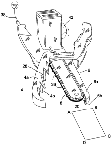
Referring particularly to figure 1 of the drawings, a vegetation pruning
device
shown generally as 2 is shown. In the example shown in Figure 1, it can be
seen that
the pruning device comprises a pair of pivotally coupled arms 4 and 6. In this
example the upper arm 6 of the pair of arms 4, 6 comprises a composite
structure
formed from a cutting element 8 and an outer portion 10 biased towards the
cutting
element 8. A pivot point 12, in this embodiment an appropriate through bolt,
articulates the first arm 4 of the pair of arms to the second arm 6 of the
pair of arms
so that the arms 4, 6 can be "open" and "closed" by appropriate relative
movement of
respective handles 14 and 16 of the arms. .
Referring now particularly to figure 2 it can be seen that a.user may move the
handles 14, 16 apart from one another (as indicated by arrow A) such that the
arms
4, 6 also move apart from one another to the "open" position via the pivot
point 12. It
can be seen from this figure that opening the arms 4, 6 exposes the cutting
element
8 such that vegetation for pruning may be introduced into the space between
the arm
4 and cutting element 8. The corollary to this, of course, is that in figure
1, where the
arms 4, 6 are shown in the "closed" position, the cutting element 8 is
generally
CA 02473869 2004-07-13
14
shielded such that it is substantially inaccessible. This will become more
understandable from the description below and particularly with reference to
Fig 6.
One or more locking devices (not shown) releasably lock the arms 4, 6 in the
"closed" position relative to each other and can be released in a manner to be
described in greater detail below to allow the arms 4, 6 to be pivoted
relative to each
other to the "open" position.
Referring now particularly to figure 3 it can be seen that the cutting element
8,
in this example a linked chain, passes over a support member, in this exampie
a
longitudinally extending chain bar 20. A longitudinal section taken through
the chain 8
is shown in figure 7. It can be seen here that the chain 8 comprises a
plurality of
links 22 which serve to interconnect sets of pairs of chain elements 24. The
construction of the linked chain 8, in this manner, therefore, is
conventional. Such a
style of chain is used, for example, in chain saws for cutting trees and also
on
bicycles and motorbikes for providing motive force. Also shown in figure 3,
although
not essential to the operation of the invention, are a plurality of barbs 26
coupled to
the chain 8 used to assist in the cutting operation of the chain 8. It will be
apparent to
those skilled in the art that a conventional chain saw uses a linked chain
with such
barbs attached thereto. The purpose of the barbs 26 is to provide the cutting
or
slicing action of the chain in the vegetation to which it is presented. This
chain 8 and
chain bar 8 are similar to those employed in a conventional chain saw but, for
the
purpose of understanding the present invention, simply represent a powered
cutting
element.
It can also be seen from figure 3 that the chain 8, which is mounted upon and
surrounds the chain bar 20, extends within a plane shown as ABCD in the
drawing.
It can be seen from figure 3 and also Fig 6 that the arm 4, and the outer
portion 10 of
arm 6 includes side cover portions - respectively 4a, 6a and 4b, 6b - which
serve,
when the arms 4, 6 are in the "closed" position (in Figure 1), to at least
partially
encapsulate or surround the chain 8. With reference to Figure 1a it is seen
that the
cover portion 6 comprises two substantially parallel side plate members (6a
and 6b)
having a space therebetween slightly greater than the maximum width of the
chain
and/or chain bar 20. The outermost edges 6c of each of the plates 6a and 6b
are
CA 02473869 2004-07-13
interconnected by a substantially perpendicular outer plate member (not shown)
such
that this arm portion 6, in cross section, presents a substantially U-shaped
profile into
which the chain (or powered cutting element) may be at least partially
accommodated. The front end of this arm 6 is further curved so as to partially
5 enclose the front end of the curved end of the cutting element as shown in
Figure 1a.
It is also possible for the arms 4, 6 to abut each other at their front ends
in the dosed
position to completely restrict access to the front end of the cutting element
8.This
significantly improves the safety of the apparatus, since accidents can result
from
inadvertent contact between the front end of the cutting element 8 with a
workpiece
10 or the ground, causing loss of control over the apparatus, or the flex
supplying
electric power to motor 36 can be inadvertently cut by passing into the gap
between
the arms 4, 6.
The plate member connecting outermost edges 6c of plates 6a, 6b of arm 6
15 may include a panel (not shown) which can be opened to give access to the
chain 8
inside arm 6, for example to repair the chain 8 or replace it when it becomes
wom.
The safety of the pruning device 2 can be further enhanced if the panel is
connected
to an electrically and/or mechanically operated interlock mechanism (not
shown)
which only allows the panel to be opened when the motor is switched off and/or
the
arms 4, 6 are in the "closed" position. The interlock mechanism may also be
arranged to prevent actuation of the motor when the panel is open.
Altematively, or in addition, a so-called nose guard (not shoVvn) can be
provided which restricts access to the front end of the cutting element 8.
This can
abut or enclose the front ends of arms 4, 6 when in their closed position to
also
prevent opening of the arms 4, 6 relative to each other.
With regard to Figures 1 a and 1 b the proposed arm member 4 is again
provided with a substantially U-shaped cross sectional profile (Figure 1 b)
into which
at least part of the chain 8 may be accommodated (as indicated in hashed lines
in
Figure 1b). Thus in the enclosed configuration, the arm members 4 and 6 serve
to at
least partially encompass the powered cutting element (chain 8). Both arms 4
and 6
are provided with curved front end portions to also partially enclose the
front curved
end of the cutting element.
CA 02473869 2004-07-13
16
It can be seen from figure 1, therefore, that when the arms 4, 6 are in a
closed
position direct access to the chain 8 (and, in particular the barbs 26
attached thereto)
is not possible. This provides a significant safety feature for the user of
the
vegetation pruning device 2 in accordance with the present invention. By
providing
that each of the cover portions 4a, 4b and 6a, 6b of their respective arms 4,
6 extend
in a direction parallel with the plane ABCD, yet each of these extensions are
arranged to be laterally offset both from the plane in which the chain 8
rotates and
physically from the chain 8 itself, then access to the chain 8 by user from a
direction
perpendicular to this plane ABCD is not possible when the arms 4, 6 are in a
closed
position. The arm members 14 and 16 are designed so that when brought into the
closed configuration as shown in Figure 1 the handle portions will engage one
another to define a limited end stop to the pivoted closed position (Figure
1). In this
embodiment, the arm member 16 is provided with a motor housing 17 (to be
described below) against which an inner portion 19 of the upper handle 14 (the
term
inner used to indicate proximate pivot axis 12) which engages to define this
end stop
position (Figure 1). This defined end stop position causes the side cover
portions 4a
and 4b of the arm 4 to partially enclose the blade but retain the arm portion
4 in a
position whereby its inner face 4c (Figure 1 b) is restrained from engaging
with the
blade 8 as shown. Thus, the arm member 4 whilst able to partially enclose the
cutting element is restrained from engagement therewith when in an enclosed
configuration. Similarly, and as will be described in more detail below, the
upper arm
6 is pivotally biased to the position substantially shown in Figures 1, 1a and
2 so that
it will partially enclose the cutting element or chain 8 but has a stop
position as
shown which prevents it from being displaced into engagement with such cutting
element, again allowing the cutting element to be partially enclosed thereby
but is
restrained from interference with such cutting element operation.
It can be seen from the figures that, in this embodiment, the arm 4 has a
plurality of indentations or projections thereon, in this example projecting
teeth 28,
which are employed in use of the pruning device, to restrain vegetation being
cut by
the chain 8 in a largely immovable position relative to the arms 4, 6 and the
cutting
element 8. It will be apparent that in order to effect efficient pruning of
vegetation,
the vegetation to be pruned needs to be held steady relative to the cutting
element so
that an accurate cut can be obtained. The purpose of the teeth 28, therefore,
is to
CA 02473869 2004-07-13
17
achieve such function. If desired, the teeth 28 could also be formed on the
arms 6 in
addition or altematively to that of the arm 4. Also any suitable shape or
profile of
such indentations or projections which achieve the holding the vegetation
steady
relative to the cutting element are equally efficacious. As seen in Figures 1
and 2 the
direction of rotation of the chain 8 is indicated by the arrows on the chain
bar 20. The
specific use of the saw tooth teeth 28 is such that rotation of chain 8 will
cause it to
engage with any workpiece placed between it and the jaws 4 whereby the cutting
action will attempt to displace the branch or workpiece in a direction towards
the pivot
axis 12 which will, in practice, serve to drive such workpiece or branch into
positive
engagement with the teeth 28 therefore enhancing the gripping effect resultant
from
use of such teeth 28. If teeth are employed on the arm member 6 then it is
preferred
such saw teeth will be inclined in an opposite direction to that of arm 4 so
as to again
cause any workpiece being cut to be forced into positive retaining engagement
therewith in a similar manner to employment of the teeth 28.
In order to provide a motive drive force to the chain 8 the proximal end (that
is
the one remote from the plane ABCD in figure 3) of the chain bar 20 includes a
drive
wheel or sprocket 30 (shown in Fig 1a and Fig 6 but not visible in the other
figures)
which engages and drives the chain 8 in a conventional manner.
Also, it will be apparent, that the distal end of the chain bar 20 includes a
driven
wheel or sprocket 32 (again, shown in Fig 1 a and Fig 6 but not visible in the
other
figures) to allow rotation of the chain 8 around the chain bar 20. The chain
8, when
driven by the drive sprocket 30, therefore, rotates in a continuous loop about
the
extemal periphery of the chain bar 20. It can be seen from Fig 6 that the
drive
sprocket 30 is coupled to an output shaft 34 of an electric motor 36. In the
example
shown the motor 36 provides a direct rotary output for the output shaft 34,
although
those skilled in the art will appreciate that, dependent upon the conditions
of use of
the pruning device, a gearbox (not shown) between the motor 36 and the drive
sprocket 30 may be useful in order to adjust the amount of torque and/or the
rotational speed exhibited by the chain 8 as it is being driven. In this
manner, the
cutting element operates as a conventional cutting element of a chain saw.
CA 02473869 2004-07-13
18
Power for the motor 36 is provided in conventional manner by power supply
cable 38 which will be coupled to a source of mains power or the like.
(Altematively,
albeit not shown, power could be supplied by a battery or petrol engine). In
one
particularly advantageous implementation of the invention, the motor 36 is
powered
by a rechargeable battery, which is arranged on the housing of the apparatus
on the
opposite side to the motor 36. This allows a particularly ergonomic
arrangement in
which the weight of the rechargeable battery balances that of the motor 36 so
that
the centre of gravity of the apparatus is as near as possible to the central
plane of the
apparatus. Operation of the motor 36 is dependent upon actuation of a trigger
switch
40 by the user of the device 2. The trigger switch 40 is conveniently mounted
upon
one of the handles, in this example, handle 14. By mounting the trigger 40 on
the
handle it is easy for the user of the device not only to hold and operate the
device,
but then also to have a readily available means of activating or deactivating
the motor
36. Additionally, it is entirely feasible (although optional) for there to be
a secondary
operating device mounted upon the other handle 16. This would operate as a
"failsafe" mechanism whereby unless both actuators were depressed or activated
by
the user then the device would be inoperable. This is useful in situations
such as
those where the user would be in an elevated position up a ladder, or the
like, and
possibly reaching in order to cut vegetation. It is known that these
situations are
potentially dangerous and so ensuring that the user must have both hands on
the
pruning device 2 in order to operate it is desirable. An example of such a
secondary
failsafe mechanism is illustrated by a secondary displaceable switch member 41
which again is readily accessible via a users fingers when gripping the handle
16.
The use of dual switching mechanisms are conventional within many forms of
power
tools and their specific operation need not be described in any great detail
here.
However, their operation may be electrical or a combination of electrical
mechanical
mechanisms. For example operation of the motor will be prevented unless both
switch elements 41 are displaced from an unactuated to an actuated position.
In this
manner the failsafe mechanism may simply comprise an electrical connection to
the
motor requiring a dual electrical input or may in fact provide some form of
mechanical
stop mechanism preventing electrical connection between the switch member 41
and
the motor. A particular advantage in this invention will be determined that
should the
users grip on either handle be released then operation of the motor is
immediately
stopped.
CA 02473869 2004-07-13
19
The trigger switch 40 in this embodiment not only controls actuation of the
motor 36 but, dependent upon the amount of pressure applied thereto by user,
dictates the speed of output of the motor 36. Such switches are readily
available in
the art.
The safety of the pruning device can be further enhanced by having a braking
arrangement for bringing the chain 8 to a halt as quickly as possible when
power to
the motor 36 is interrupted. One way of achieving this is to arrange for the
motor 36
to be short circuited when the switch 40 is released, so that the motor 36
acts as an
electromagnetic brake.
It will be appreciated from the above that the teeth of both the drive
sprocket 30
and the driven sprocket 32 operate to engage the chain 8 in a conventional
manner.
Clearly the frictional contact which occurs by virtue of this engagement and
also the
wear of the chain 8 around the periphery of the chain bar 20 may cause a
significant
amount of heat to be generated. It is therefore advisable for not only some
lubrication to be applied to the entire cutting element mechanism including
its drive
means, but also a mechanism provided for varying the tension felt by the chain
8 if it
wears during use.
In order to provide lubrication for the chain 8 and its drive mechanism 30,
32,
34 therefore, there is provided an oil reservoir 42 mounted adjacent the drive
sprocket 30 and able to dribble lubricating oil onto the drive sprocket 30
during use of
the motor 36. The lubrication mechanism can have a lubrication reservoir (not
shown) arranged inside the lighter handle 14, as a result of which the
apparatus is of
compact construction, and the weight of the apparatus is balanced as evenly as
possible. The lubricating mechanism can be arranged to dispense a fixed amount
of
lubricant in response to opening of the handles 14, 16 relative to each other,
or in
response to opening and then closing of the handles 14, 16 relative to each
other. It
is also possible for the lubricating mechanism to take higher levels of
heating of the
chain 8 into account by controlling the amount of lubricant dispensed in
dependence
upon the speed at which motor 36 is driven, so that more lubricant is
dispensed at
higher operating speeds of the motor 36.
CA 02473869 2004-07-13
The chain tensioning mechanism employed in this specific embodiment is
again one conventionally employed in the art of chain saws. The chain bar 20
(as is
shown in Figure 1 a) is securely mounted to the arm member 16 in the region of
the
motor housing 17 by an appropriate threaded bolt member (not shown). Such a
5 threaded bolt member will have a first engaging face against which one side
of the
chain bar 20 is received and a second threaded nut member is then rotatably
received on such bolt so as to compress the chain bar 20 therebetween.
Operation
of this nut or bolt can be achieved in a number of conventional manners but
will
usually employ an extemal sprocket member which can be manually rotated as
10 appropriate. In the event that use of the cutting element causes a
loosening of the
chain (such as by stretching of the distance between adjacent link elements),
the
chain bar 20 may then slideably displaced about this bolt member in a
direction away
from the pivot axis (12) of the pruning device by firstly loosening the nut
member of
the nUt and bolt restraining mechanism and manually displacing the blade in a
15 direction away from such pivot axis 12 effectively increasing the distance
between
the sprocket 32 and the sprocket 30 causing the tightening of the chain
thereabout.
Once appropriate tightening has been achieved the chain bar 20 is fixed into
the new
position by appropriate retightening of the nut and bolt member. This chain
tension
device is conventional for chain saws.
Referring now to figures 4 and 5, in that order, operation. of the device 2
will be
described. The large cylindrical object 44 in the drawings is representative
of
vegetation to be pruned and, in this example, is meant to represent a section
of a
branch or a bush or the like. Assuming firstly that the arms 4, 6 are in the
"open"
position (Figure 2) and the branch 44 is placed between the lower surface of
the
chain 8 adjacent the teeth 28 of arm 4, then the user will close the handles
14, 16 of
the device until such time as the branch 44 contacts the lower surface of the
chain 8
with its upper portion 44a and the teeth 28 of the arm 4 with its lower
portion 44b. As
the user squeezes the trigger 40, the chain 8 is caused to rotate and the
barbs 26
formed thereon will cut into and through the branch 44 in known manner. Whilst
this
is occurring, the user continues to effect closing of the handles 14, 16 so as
to effect
a biasing force on the branch 44 into engagement with such cutting element. As
the
handles 14, 16 move closer together, the force applied thereto acting through
the
pivot point 12 causes the arms 4 and 6 also to move closer together. In this
manner,
CA 02473869 2004-07-13
21
therefore, the branch 44 is effectively squeezed between the lower arm 4 and
the
chain 8 and its chain bar 20 causing cutting of the branch 44. The position in
Fig 4,
therefore, is that of the branch 44 having been cut through about half of its
diameter.
Continued force applied to the handles 14, 16 in order to bring them closer
together results in the position shown in Fig 5. Here it can be seen that the
arm 4
has been brought into its completely closed position such that the side cover
portions
4a and 4b of the arm member 4 effectively shield the lower portion of the
chain 8
from any contact by the user although the teeth 28 still engage in retaining
the
branch either side of such cutting element (as shown). It will be noticed,
though, that
the outer portion 10 of the upper arm 6 has been pivotally displaced from its
position
as shown in any of the other figures. In this particular embodiment, the upper
portion
10 of the upper arm 6 is pivotally connected to such arm members 6 and biased
towards an end stop position as shown in Figures 1 and 2 so as to closely abut
and
partially enclose the cutting element or chain 8. This functions as a chain
guard
mechanism. However, such a chain guard, if not pivotal, would limit the depth
of
branches that could be cut to the depth of the chain bar 20. However, by
making
such outer portion 10 pivotal, then as the branch 44 passes over the chain bar
20
during the cutting operation and as shown in Figure 5, the upper portion 44a
will
eventually be forced in abutment with this outer portion 10 whereby the
continued
displacement of the branch past the cutting bar will effect pivotal
displacement of the
outer portion 10 as shown in Figure 5 allowing the branch to continue to move
past
the chain 8 and the chain bar 20 in order to effect complete cutting thereof
of any
branch having a depth greater than that of the chain bar 20. Once the cut
branches
are then removed from the pruning device, the spring biasing of this outer
portion 10
causes this portion 10 to move back into position shown in Figure 1
effectively
providing its function as a chain guard. As mentioned, this chain guard is
limited in
its pivotal displacement so as not to be brought into engagement with the
chain but to
partially encompass it as shown in Figure 1a. This provides for a variable
cutting
depth irrespective of the depth of the chain bar 20.
Having a movable portion of the arm 6 is necessary in this example as the
portions 6a, 6b of the arms which sit either side of the chain 8 in the
direction
perpendicular to the plane ABCD would otherwise simply abut the upper surface
of
CA 02473869 2004-07-13
22
the branch 44 and prevent further closing of the arm 4 toward the chain 8 and
chain
bar 20. As shown in from Fig 5, the spring providing the spring loading of
outer
portion 10 of the arm 6 is shown at 46.
Referring now to Figure 1 c, showing the opposed side of the pruning device of
Figure 1, the device is provided with an appropriate dust or chip extraction
aperture
100. As will be appreciated from Figures 4 and 5, the cutting operation of the
chain 8
causes wood chippings and sawdust to be drawn towards the motor housing 17 and
sprocket 30. Such movement is further enhanced by the formation of the U-
shaped
channel formed in arm member 4. As such, a lower portion of the motor housing
17
is provided with an appropriate internal channel and extemal aperture 100 so
that
any sawdust or wood chippings drawn into the motor housing are simply
extracted so
as to fall out of this aperture whereby the speed of rotation of the chain
witt create an
appropriate airflow serving to drive the wood chippings out of the tool.
One of the major benefits of the current invention is the ability to provide a
means of rigidly securing the branch or workpiece 44 in close proximity with
the
blade during the cutting operation. In this particular embodiment a further
enhancement provides that the cutting element is partially encompassed so as
to
prevent inadvertent access thereto providing an enhanced safety feature for
the
operator. In a further variant (not shown) the invention can be further
modified so
that operation of the cutting element of the embodiment in Figures 1 to 5 is
prevented
in the absence of an article to be cut being placed between the cutting
element and
the jaw 4. This could be achieved by providing an appropriate sensing
mechanism
registering the presence of a branch between such cutting element 8. An
example
would be the provision of a further limited pivot action of the lower arm 4
which would
be biased to the position conventionally shown in Figures 1 to 5. The degree
of
pivotal displacement of this arm 4 about this additional pivot point would be
limited to
only a few degrees whereby when a branch is displaced between this arm 4 and
the
cutting element 8 and the jaws closed, the resistance of the branch 44 would
cause a
slight pivotal displacement of the arm 4 against its associated biasing.
Detection of
this pivotal displacement would then be indicative of the presence of a branch
to be
cut and an appropriate facility employed within the device to allow operation
of the
motor on activation of the switches as previously described. Again, such
feature
CA 02473869 2004-07-13
23
could be mechanical or electrical. In the event of an electrical operation,
one
example would be that when the jaw 4 is in its pivotally closed position as
shown in
Figures 1 to 3, then an appropriate electrical contact activates an
appropriate
switching element preventing operation of the motor. Once such electrical
contact is
broken (by the pivotal displacement effected by detection of a branch)
operation of
the motor can then be initiated. A further enhancement of this type of pivotal
detection system will be that once the branch has been completely cut through
and
falls away from the tool such biasing force on the jaw 4 will be removed
causing it to
return to its normal position by the inherent resilient biasing causing
closure of the
aforementioned electrical contact and hence cessation of operation of the
motor,
stopping the tool. Thus, not only would this permit the tool to be operated
oniy in the
presence of a branch but that operation of the tool would automatically cease
once
that branch had been completely cut through.
Although in the example shown in figures 1 to 5 the cutting element 8 and the
outer portion 10 of the arm 6 biased towards the cutting element 8 together
comprise
one arm 6 of the pair of arms 4, 6, it will be appreciated that these may be
fonned as
separate elements. For example, it could equally be the case that whilst one
arm 4
of the pair of arms is a shown in the drawings, the other arm could actually
comprise
the chain bar 20 and its associated chain 8. In this example, therefore, the
feature
which is labelled 10 in the diagrams would not actually formed part of the
other arm
of the pair but would be a pivoting spring biased portion formed as a separate
element. This distinction is not germane to the present invention, however.
It will be understood by those skilled in the art that the sense of rotation
of the
chain 8 about its chain bar 20 determines the orientation of the teeth 28.
Also this
sense of rotation will determine between which arm 4 or 6 as shown in the
drawings
and the chain 8 the branch 44 to be cut is presented. Clearly it is not useful
for the
chain to rotate in the sense which causes the branch 44 to be pushed away from
the
pruning device but rather pulled in towards the pruning device 2 and, even
then, to
be engaged in as non-movable a manner as possible by the teeth 28.
In a further enhancement of the present invention, now shown in Figures 8
through 10, there is provided a self-adjusting blade or chain tensioning
device to
CA 02473869 2004-07-13
24
replace the manually adjustable chain tensioning device shown with - reference
to
Figure 1a.
Referring now to Figure 8 there is a shown an alternative pruning device 2"
(identical to pruning device 2 of Figure 1 with the exception of this chain
tensioning
device) having such a modified blade tensioning device shown generally by
arrows
450. As discussed above, where the cutting element comprises a chain 458
mounted on an appropriate support member (or chain bar) 460 for such chain 458
to
extend between a first driven wheel or sprocket member 462 and a driven (or
sprocket) wheel member 464 then use of the cutting chain 458 will incur
considerable
vibration, often effecting displacement of the support member 460 thus causing
the
chain to loosen. It is necessary that the support member 460 is adjustable so
as to
allow the chain to be retensioned as appropriate.
Referring now to Figure 9 the self-adjusting device 450 is shown in more
detail.
This device 450 comprises a primary mounting block 466 securely mounted to
the motor housing 417 and hence handle portion 416 so as to be effectively
integral
therewith. Adjustably mounted on this mounting block 466 is a steel
compression
plate 468 which is adjustable relative to and away from the mounting member
466
(as indicated by arrow 500) so as to effectively compress or release an
intemal end
portion 470 of the support member 460, as schematically illustrated in Figure
8. Here
it can be seen that the inner portion 470 of the support member 460 has a
substantially rectangular rebate 461 allowing it to pass over an appropriate
screw
threaded member (not shown) upon which the compression plate 468 is mounted
whereby a conventional wing nut (471) or other rotatable member (eg. a
rotatable
knob) can then be used to adjust the compression plate towards or away from
the
mounting member 466 so as to compress and hold, or altematively, release the
support member 460 disposed between such plate 468 and block 466. Accordingly,
this compression plate 468 is a greater size than rebate 461 to allow positive
engagement of the plate 468 with the support member 460. The device 450 is
further provided with an internal elongate channel 472 slideably accommodating
a
plunger 474 which is spring loaded via an appropriate coil spring 476 disposed
between an intemal end of the channel 472 and the plunger 474 as shown. The
CA 02473869 2004-07-13
channel 472 is substantially square in cross section so as to retain the
plunger in a
desired displaceable orientation relative to the support member 460 as will be
described below. The plunger is further provided with a series of ratchet
teeth 476
inclined in a direction away from the mounting block 466 as shown. An
appropriate
5 non-retum ratchet pawl 478 is then rigidly connect to the mounting member
466 so
as to engage with the ratchet teeth 476 to prevent a return of the ratchet
member 476
back into the mounting member 466 once displaced there out of by the spring
member 476. In practice, this non-return ratchet pawl will be provided with an
appropriate adjustment means which allows it to be displaced out of engagement
10 with the ratchet teeth when the self-adjusting device is to be released to
allow
removal of the, chain and necessary reduction in tension thereof to allow such
removal.
In practice, the support member 460 and the self-adjusting device 450 will be
15 constructed as shown in Figure 8 with an outer end surface 480 of the
plunger 474 in
abutment with an intemal surface 482 of the rebate 461 of the support member
460
as shown in Figure 8. When the compression plate 468 is in a released
position,
disposed away from the block 466, the support member 460 is no longer
frictionally
restrained against the mounting block 466, whereby the inherent resilient
biasing of
20 the coil spring 476 (which is set at between 5lbs and 101bs pressure in a
normal
embodiment but could be anywhere between 51b and 301bs of pressure) exerts a
biasing force on the plunger 480 which is exerted against the intemal surface
482 of
rebate 461 so as to effect adjustment of the support member away from the
support
blocking a direction as shown by arrow 490 in Figure 8. The amount of
displacement
25 effected on the support member 460 by such biasing force is limited by the
size of
the chain member 458 but in this released configuration the self-adjusting
device 450
serves to apply sufficient force to the support member 460 to effect
appropriate
tensioning to the chain 458 as required. The compression plate 468 can then be
adjusted so as to clamp the support member 460 against the mounting member 466
to hold it in the self-adjusted, tensioned configuration. In practice the non-
retum
ratchet pawl 478 will assist in maintaining the plunger in this appropriate
position. In
the event that there is subsequent loosening of the chain which requires the
device to
be re-tensioned, this is simply achieved by again releasing the compression
plate
468 by adjustment of the appropriate rotatable release mechanism (wing-nut
471)
CA 02473869 2004-07-13
26
whereby the biasing force of the coil spring 476 then effects sufficient
displacement
of the support member 460 to automatically re-tension the chain. This re-
tensioned
chain can then be damped in position by retightening of the wing nut 471
compression plate 468 as previously described.
In the event that a user wishes to remove or replace the chain member 458 this
is simply achieved by releasing the non-return ratchet pawl and applying
sufficient
force to the free-end of the support member 460 to overcome the biasing force
of the
spring 476 to effect sufficient displacement of the support member 460 towards
the
drive wheel 462 to allow the chain to be removed from such support member 460.
However, this specific embodiment provides an enhanced and simplified
means of self-adjusting tensioning of a chain about a support member which
simply
allows loosening of the appropriate wing-nut on the compression plate 468 to
effect
appropriate self-adjustment of the chain tension.
Basically, this self adjusting blade tensioning device 450 effects relative
displacement between the two support wheels 464 and 462 as shown. This is
achieved by mounting the driveable support wheel 464 on the support member 460
and securing the tensioning device 450 so as to be immovably displaced
relative to
the driven support wheel 462.
It is to be appreciated that this specific feature of self-adjusting blade
tensioning
device is not limited to use with a shear arrangement of the embodiments of
Figures
1 to 7 but is equally applicable to any device utilising a rotatable chain
where a
minimum tensioning of the chain is required to be maintained and regularly
adjusted,
for example, conventional chainsaws or even bicycles. In addition, whilst the
use of
a wheel-nut is envisaged being mounted on a conventional screw threaded member
to effect adjustment of the compression plate 468, alternative means of
adjustment of
this compression plate 468 to and away from the mounting block 466 is readily
envisaged and could simply be a conventional nut mounted on a screw threaded
member or even a hydraulic compression arrangement.
CA 02473869 2004-07-13
27
It will be appreciated by persons skilled in the art that the above
embodiments
have been described by way of example only and not in any limitative sense,
and
that various alterations and modifications are possible without departure from
the
scope of the invention as defined by the appended claims.
For example, the arms 4, 6 can be arranged to control access to chain 8 to
enhance the safety of the apparatus, for example by biasing the anns 4, 6
towards
their closed position by means of one or more springs, and/or by having an
openable
guard on one of the arms 4, 6 to allow access to the chain 8 to enable the
chain 8 to
be replaced when it becomes worn. An interlock arrangement can prevent the
guard
from being opened when the motor 36 is actuated and/or when the arms 4, 6 are
in
their open position relative to each other offering access to the cutting
element 8, and
can prevent the motor from being actuated when the guard is open. Also, it
will be
appreciated that the cutting element can be driven in a number of ways, for
example
by means of motor 36 having an output shaft arranged generally parallel to the
axis
of rotation of sprocket wheels driving the cutting element, or generally
perpendicular
to such axes, rotation of the output shaft of motor 36 driving one of the
sprockets by
means of one of more conical gears, or a gear plate rotated about an axis
perpendicular to the axis of the output shaft and having gear teeth on its end
face.
One or more of the arms 4, 6 can also be arranged to have cutting edges on the
face
thereof facing away from the cutting element 8, so that the cutting edges can
be used
to effect manual cutting of vegetation by means of opening of the arms 4, 6
relative to
each other.