Note: Descriptions are shown in the official language in which they were submitted.
CA 02474423 2004-08-06
WO 03/065917 PCT/US03/03687
AN ELECTROSURGICAL INSTRUMENT HAVIT1G A
PREDETERh~iIIvIED HEAT PROFILE
BACKGROUND OF THE INVENT10N
1). Field of the Invention
[0001] This invention relates to an elertrosurgical instrument of the kind
used
for electrosurgical arthroscopy.
2). Discussion of Related Art
(0002] Arthroscopic surgery is often used to treat degenerating cartilage.
Cartilage on the back of the patella, for example, tends to wear down due to
overuse into collagen fibrils having bases attached to remaining viable
cartilage.
The fibrils themselves then tend to cause acceleration in the degeneration
process
of the viable cartilage, and the "wear" debris from the fibrils irritates the
joint
liming. This irritation can be a source of pain as the fibrils break down and
break
off as debris which may necessitate joint replacement.
[0003] There are several interventions a surgeon may choose when addressing
these lesions of the articular cartilage. While some surgeons feel. the
lavaging
(irrigating) the joint is sufficient, many more surgeons endeavor to remove
the
excess material in an attempt to decrease the "wear" debris that originates
from
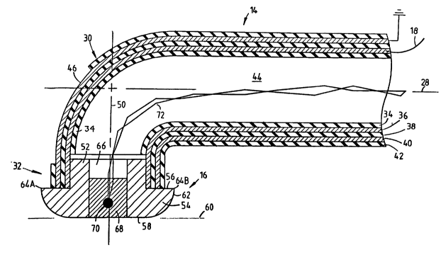
these strands of cartilage. One common way of addressing these lesions is with
CA 02474423 2004-08-06
WO 03/065917 PCT/US03/03687
the use of mechanical shavers as are commonly used in arthroscopic surgery to
"shave" off the long fronds of cartilage. This procedure is called a
chondroplasty.
[0004] In another arthroscopic treatment method, a surgeon inserts an
electrosurgical probe through an incision or opening formed in a body of a
patient. Radio frequency (R~ power is then provided to an electrode at the end
of the probe, which creates ohmic heating of an area surrounding the
electrode.
The fibrils are denatured by the heat when the electrode is brought into
contact
with the fibrils, which causes the fibrils to congeal together, forming an
intact
surface.
(0005] In order to effectively denature the fibrils, it is required that the
fibrils be
exposed to a relatively high temperature, for example, 70° C or
greater. Such
high temperature not only denatures the fibrils, but has the potential to
cause
permanent damage to the viable cartilage to which the fibrils are attached.
The
high temperature causes chondrocyte death because the cartilage does not
regenerate. The typical high temperature profiles of non-thermally controlled
prior art probes may also deliver too much thermal energy which may also cause
avascu1ar necrosis (AVID of the underlying bone structure, requiring total
joint
replacement.
(0006] Thus, what is needed is a surgical probe which can effectively address
the fibrils while protecting viable cartilage. The probe should be able to
deliver a
CA 02474423 2004-08-06
WO 03/065917 PCT/US03/03687
controlled amount of energy for thermal treatment with a variable temperature
profile to treat the different tissues at the surgical site.
CA 02474423 2004-08-06
WO 03/065917 PCT/US03/03687
BRIEF SUMMARY OF THE INVENT10N
[0007] According to one aspect of the invention, an electrosurgical instrument
is
provided, having a holding formation, an elongated probe, at least one
electrode,
and a conductor. The elongated probe is connected to and extends from the
holding formation. The at least one electrode is located on an end of the
elongated probe opposing the holding formation, and forms at least part of an
electrode structure that has a leading edge and a face. The at least one
electrode
is locatable so that the face is substantially in a horizontal plane and the
leading
edge is above the horizontal plane. The conductor extends along the elongated
probe and has a portion connected to the at least one electrode to provide RF
power thereto. The at least one electrode creates a temperature profile with a
temperature adjacent to the leading edge being higher than a temperature
adjacent to the face.
[0008] The leading edge and the face are preferably on a single electrode.
[0009] The leading edge may have a smaller radius of curvature than the face.
The face may be substantially flat. The leading edge may be substantially
sharp.
The leading edge may point in a direction away from the horizontal plane.
[0010] There is preferably no material of the electrode directly below the
leading edge in the horizontal plane.
[0011] The electrode may have a convex cam surface between the leading edge
4
CA 02474423 2004-08-06
WO 03/065917 PCT/US03/03687
and the face. The convex cam surface may extend up to the leading edge.
[0012] The at least one electrode may have a trailing edge on a side of the
face
opposing the leading edge. The trailing edge may be at substantially the same
distance from the horizontal plane as the leading edge.
[0013] The electrode may have an electrode opening therein. The electrode
opening may have a diameter which is less than 50% of a diameter of the
electrode measured in the same plane. The electrode opening may extend
through the face. The electrosurgical instrument may further include a
thermally
conductive plug in the opening at or near the face, and a thermocouple in
contact
with the thermally conductive plug. The thermally conductive plug, at or near
the face, is preferably made of an electrically insulating material.
[0014] Preferably, a line at right angles to the horizontal plane is at an
angle
with respect to an axis of the elongated probe. The angle may, for example, be
at
least 30°.
[00151 A lower surface of the elongated probe may be above the horizontal
plane.
[0016] The holding formation may, for example, be a handle.
[0017] A method is provided for treating degenerative collagen fibrils, having
bases attached to viable cartilage. A surface of an electrode structure is
located
adjacent to viable cartilage. A temperature profile is generated having a low
temperature adjacent to the face and a high temperature at a location further
CA 02474423 2004-08-06
WO 03/065917 PCT/US03/03687
from the viable cartilage than the face. The electrode structure is moved in a
direction substantially parallel to a plane of the viable cartilage. Such
movement
first exposes each fibril to the location of the temperature profile having
the high
temperature, whereafter the surface moves over the fibrils.
[0018] Preferably, the location on the temperature profile having the higher
temperature passes through an imaginary plane normal to the plane of the
viable
cartilage before the face passes through the imaginary plane.
CA 02474423 2004-08-06
WO 03/065917 PCT/US03/03687
BRIEF DESCRIPT10N OF THE DRAWINGS
[0019] The invention is described by way of examples with reference to the
accompanying drawings, wherein:
(0020] Figure 1 is a cross-sectional side view illustrating an electrosurgical
instrument according to an embodiment of the invention;
[0021] Figure 2 is a cross-sectional side view of a distal end of a composite
elongated probe of the electrosurgical instrument, and an electrode attached
to
the distal end;
[0022] Figure 3 is a cross-sectional side view illustrating isotherms
generated by
the electrode;
[0023] Figure 4 is a cross-sectional side view illustrating pivoting of the
electrode;
[0024] Figure 5 is a side view illustrating how the electrode is used to treat
degenerative collagen fibrils attached to viable cartilage;
[0025] Figure 6 is a side view illustrating one alternative embodiment of an
electrode;
[0026] Figure 7 is a side view illustrating another alternative embodiment of
an
electrode;
[0027] Figure 8 is a side view illustrating a further alternative embodiment
of
an electrode; and
CA 02474423 2004-08-06
WO 03/065917 PCT/US03/03687
[0028] Figure 9 is a perspective view of an electrode structure having an
electrode and an electrically insulating material forming a face of the
electrode
structure, according to yet a further embodiment of the invention.
s
CA 02474423 2004-08-06
WO 03/065917 PCT/US03/03687
DETAILED DESCRIPTTON OF THE INVENTION
[0029] Figure 1 of the accompanying drawings illustrates an electrosurgical
instrument 10, according to an embodiment of the invention, including a handle
12, a composite elongated probe 14, an electrode 16, an electric cable 18, and
an
electric connector 20.
[0030] The electric connector 20 is connected one end of the electric cable 18
and
an opposing end of the electric cable 18 is secured to a rear end 22 of the
handle
12. A proximal end 24 of the composite elongated probe 14 is secured to a
front
end 26 of the handle 12 opposing the rear end 22. A common horizontal axis 28
extends through the handle 12 and the composite elongated probe 14. In this
embodiment, a bend 30 is formed in the composite elongated probe 14 just short
of a distal end 32 thereof and the electrode 16 is secured to the distal end
32.
Another embodiment may have no bend at the distal end.
[00311 Referring now also to Figure 2, the composite elongated probe 14
includes a plurality of concentric coatings and tubes, including an inner
insulator
34, a metal power conductor 36, and intermediate insulator 38, a metal ground
conductor 40, and an outer insulator 42. The inner insulator 34 defines a
passage
44 extending therethrough. The power conductor 36 is located around the inner
insulator 34, and is insulated from the passage 44 by the inner insulator 34.
The
intermediate insulator 38 is located around the power conductor 36. The ground
CA 02474423 2004-08-06
WO 03/065917 PCT/US03/03687
conductor 40 is located around the intermediate insulator 38, and is insulated
from the power conductor 36 by the intermediate insulator 38. The outer
insulator 42 surrounds the ground conductor 40 and provides an insulated outer
surface for the composite elongated probe 14. Only a portion 46 of the ground
conductor 40 near the distal end 32 is exposed on an external surface of the
composite elongated probe 14. The electric cable 18 is attached to the power
conductor 36 near its proximal end 24. The conductive metal may be a
biocompatible metal such as nickel, stainless steel, platinum, tungsten, or
their
alloys, with tungsten being preferred.
[0032] The electrode 16 is made of an electrically conductive metal. Although
shown in cross-section, it should be understood that, in this embodiment, the
electrode 16 has circular dimensions which are symmetrically formed about a
vertical axis 50. The circular dimensions allow for multidirectional use and a
uniform temperature profile around the electrode 16. The geometry of the
electrode 16 may be different in another embodiment, depending on application.
[0033] The electrode 16 has an upper portion 52 having a diameter of
approximately-3 mm, and a lower portion 54 having a diameter of approximately
mm. In another embodiment, the diameter may be between 5 mm and 8 mm.
A horizontal step 56 is formed where the electrode 16 transitions from the
smaller diameter of the upper portion 52 to the larger diameter of the lower
portion 54.
CA 02474423 2004-08-06
WO 03/065917 PCT/US03/03687
[0034] The lower portion 54 has a lower face 58. The electrode is depicted
with
the face 58 in a horizontal plane 60. The lower portion 54 also has a convex
cam
surface 62 connecting the face 58 with the step 56. A tip 64 is formed where
the
step 56 and the cam surface 62 meet. A leading edge 64A of the tip is located
on
the left of the face 58 at a distance of approximately 1.3 mm above the
horizontal
plane 60. In another embodiment, the leading edge 64A may be between 1 mm
and 2 mm above the horizontal plane 60. A trailing edge 64B of the tip is
located
on the right of the face 58 at the same height from the horizontal plane 60 as
the
leading edge 64A. The leading edge 64A points upward and to the left, and the
trailing edge 64B points upward and to the right. There is no material of the
electrode 16 directly below either the leading or trailing edges 64A or 64B in
the
horizontal plane 60.
[0035] An inner surface of the power conductor 36 is exposed because the inner
insulator 34 is not located in the distal end 32. The upper portion 52 is
inserted
into and contacts the inner surface of the power conductor 36. Electric
current
can flow from the electric cable 18 through the power conductor 36 to the
electrode 16.
(0036] An electrode opening 66 is formed in the direction of the vertical axis
50
through the electrode 16. The electrode passage 66 extends into the lower face
58
through the electrode 16 out of the upper portion 52. A plug 68 of a thermally
conductive but electrically insulating solder material is inserted into the
11
CA 02474423 2004-08-06
WO 03/065917 PCT/US03/03687
electrode passage 66. A lower surface of the plug 68 is located in a plane of
the
lower face 58. A thermocouple 70 is located in the plug 68. Thermocouple wires
72 are connected to the thermocouple 70 and extend through the passage 44 to
the handle 12 for temperature feedback.
(0037] Prior to use of the electrosurgical instrument 10, an incision or
surgical
portal 80 is made in a body of a patient. For purposes of consistency, it is
assumed that the surgical portal 80 extends horizontally, and that it has
upper
and lower horizontal walls 82 and 84, respectively. A surgeon, holding the
handle 12, inserts the electrode 16 horizontally into the surgical portal 80,
followed by a portion of the composite elongated probe 14. Due to the angle of
the axis 50 relative to the axis 28, and because the lower face 58 is lower
than a
lower surface of the composite elongated probe 14, the surgeon can position
the
lower face 58 adjacent to the viable cartilage of the lower wall 84.
[0038] The connector 20 is connected to an RF source (not shown). An RF .
source generates a voltage which is provided from the RF source through the
connector 20, the cable 18, and through the power conductor 36 to the
electrode
16. The surgical portal 80 is filled with an electrically conductive fluid, so
that
the lower portion 54 of the electrode 16 is electrically connected through the
fluid
to the portion 46 of the ground conductor 40 which is exposed. A proximal
portion of the ground conductor 40 is connected to ground. A closed circuit is
thereby provided, whereby RF current conducts through the electrode 16. The
12
CA 02474423 2004-08-06
WO 03/065917 PCT/US03/03687
RF current heats the electrode 16, and the heat then radiates from the
electrode
16 to tissue of an area surrounding the electrode 16.
[0039) Figure 3 illustrates a temperature profile around the electrode 16. The
temperature profile is illustrated with isotherms 90. Clne isotherm 90A, in
cross-
section, has center points near the leading and trailing edges 64A and 64B.
The
isotherm 90A has a relatively high temperature of, for example, approximately
110° C. Another isotherm 90B located adjacent to the lower face 58 has
a
relatively low temperature of, for example, 55° C. The relatively high
temperature at the leading and trailing edges 64A and 64B can be ascribed to
the
relatively small radii of the leading and trailing edges 64A and 64B, and
particularly to the fact that they are relatively sharp. A higher current
density is
created near small radii than near large radii of the electrode 16, which
creates
the higher temperature near the small radii. The relatively low temperature
adjacent to the lower face 58 can be ascribed to the fact that the lower face
58 is
flat, and therefore has a radius of curvature (infinite), which is much larger
than
the radii of the leading and trailing edges 64A and 64B. What should be noted
is
that a relatively high temperature is created near the leading and trailing
edges
64A and 64B distant from the horizontal plane 60 in which the lower face 58 is
located. Even if the surgeon pivots the electrode 16 in a direction 92, as
illustrated in Figure 4, the cam surface 62 assists in keeping the leading
edge 64A
elevated from the horizontal plane 60.
13
CA 02474423 2004-08-06
WO 03/065917 PCT/US03/03687
[0040] Reference is again made to Figure 2. Because the plug 68 is not
electrically conductive, no heat is generated in the plug 68, which assists in
creating a more accurate and even temperature profile across the lower face
58.
The plug 68 has a diameter which is preferably at least 30% of the diameter of
the
lower face 58 to create a more even temperature profile, but preferably less
than
50% of the diameter of the electrode 16, so that the electrode 16 still has
sufficient
thermal mass. The plug 68 is, however, still sufficiently thermally conductive
so
that heat will be conducted from the electrode 16 through the plug 68 to the
thermocouple 70, which then provides temperature feedback through the
thermocouple wires 72 to the RF source.
[0041] Figure 5 illustrates how the electrode 16 is used for treating
degenerative
collagen fibrils 96 attached to cartilage of the lower wall 84. The lower wall
84
consists of viable cartilage, for example, on the rear of the patella (not
shown) or
other cartilagenous surfaces. The fibrils 96 have bases attached to the viable
cartilage of the lower wall 84. The relatively low temperature adjacent to the
lower face 58 then causes no or minimal damage to the viable cartilage. The
surgeon progresses the electrode 16 in a direction 98 substantially parallel
to a
plane of, and in contact with, the lower wall 84. Each fibril 96 is first
exposed to
the relatively high temperature adjacent to the leading edge 64A, which
partially
denatures the fibril 96. Further movement of the electrode 16 in the direction
98
moves the lower face 58 over the partially denatured fibrils 96. The lower
14
CA 02474423 2004-08-06
WO 03/065917 PCT/US03/03687
temperature adjacent to the lower face 58 causes less denaturization of the
fibrils
96, but is still sufficiently high to continue to coagulate the partially
denatured
fibrils 96 when the lower face 58 moves over the partially denatured fibrils
96.
What should be noted is that the leading edge 64A passes through an imaginary
vertical plane 100 before the lower face 58 passes thzough the imaginary
vertical
plane, so that the fibrils 96 are first partially denatured by the relatively
high
temperature adjacent to the leading edge 64A before congelation by the lower
face 58.
(0042] It can.thus be seen that the degenerative fibrils 96 are treated with
only a
minimum amount of damage to the viable cartilage in the lower wall 84 because
of the relative lower temperature. Fibrils to the right of the electrode 16
may be
treated in a similar manner by moving the electrode 16 in a direction opposite
to
the direction 98. As mentioned, the electrode 16 is symmetrical about the
vertical
axis 50, so that the electrode 16 can also be moved through fibrils in a
direction at
right angles to the direction 98 with similar results.
[0043) In the above-described embodiment, the electrosurgical instrument 10 is
of a bipolar configuration. In a bipolar arrangement, current returns through
a
ground conductor such as the ground conductor 40, and the majority of the heat
is generated within the electrode 16. In a monopolar arrangement, current does
not return through a ground conductor. Instead, a conductive pad is located on
a patient, and current returns through the patient and to the conductive pad.
In
CA 02474423 2004-08-06
WO 03/065917 PCT/US03/03687
a monopolar arrangement, the majority of the heat is not generated in the
electrode, but in material adjacent to the electrode. It is believed that a
monopolar arrangement will create a temperature profile which is similar to
the
temperature profile illustrated in Figure 3.
[0044] Figures 6 to 8 illustrate alternative embodiments of electrodes. The
electrode 116 of Figure 6 has leading and trailing edges 164 that are sharper
than
in the embodiment hereinbefore described. It is believed that the sharper the
edge, the higher temperature adjacent to the edge. The sharper edge may also
be
used for contacting or scraping of collagen fibrils. The electrode 216 of
Figure 7
is similar to the electrode 116 of Figure 6 in that it has a sharp edge 264.
In
addition, the electrode 216 has a cam surface 262 to assist in keeping the
leading
edge 264 elevated. The electrode 216 of Figure 7 also has a lower face 258
which
is not entirely flat, but is more conical in shape to allow for more
flexibility in
use. In the embodiment of Figure 8, an electrode 316 is provided which is
similar
in shape to the electrode 16 of Figure 2. A conical step 356 is formed instead
of a
flat step, so that the leading edge 364 points away from a lower face 358 at a
much larger angle than in the other embodiments hereinbefore described. Such a
large angle further assists in keeping high temperature away from viable
cartilage and possibly damaging the viable cartilage.
[0045) In all of the embodiments hereinbefore described, the electrode itself
has
a face which contacts the partially denatured fibrils, for example, the face
58 in
16
CA 02474423 2004-08-06
WO 03/065917 PCT/US03/03687
Figure 2. In another embodiment, the electrode may form only part of an
electrode structure that otherwise has the features of, for example, the
electrode
16 of Figure 2. In Figure 9, for example, an electrode structure 400 is formed
by a
combination of an electrode 402 and a thermally conductive and electrically
insulating material 404. The electrode 402 has similar dimensions as the
electrode 16 of Figure 2. However, the material 404 is formed over a face 406
of
the electrode. An outer surface 408 of the material 404 forms a face of the
electrode structure 400. The surface 408 is used for contacting partially
denature
collagen fibrils.
(0046) In another embodiment, there may be more than one electrode. It may,
for example, be possible to create a temperature profile such as in Figure 3
with
two electrodes. The two electrodes may be similar to one another, but be
energized to different levels so that one electrode is warmer than the other.
[0047] While certain exemplary embodiments have been described and shown
in the accompanying drawings, it is to be understood that such embodiments are
merely illustrative and not restrictive of the current invention, and that
this
invention is not restricted to the specific constructions and arrangements
shown
and described since modifications may occur to those ordinarily skilled in the
art.
17