Note: Descriptions are shown in the official language in which they were submitted.
CA 02474438 2004-07-08
HEADLR FOR HARVESTINhI CROPS HAVING STALKS
Fiel of the Inventic~
The invention relat$s to a header for harvesting crops having stacks, with
several intake and mowing devices arranged laterally one next to the other for
cutting and convoying ~e harvested crops, of which, on one side of the
longitudinal
Center plane of the machine thar~t Is a first intake and mowing device and a
second
intake and mowing device arranged next to the itrat device at a greater
distance from
the longitudinal center plan9 of the machine than the first intake and mowing
device,
and with a deflection conveyor unit that has a rotational axis inclined
slightly forward
in under to bridge the vertical distance bbtween the worlting plane of the
Intake and
mowing devices and the plane of the Ir>tske channel of a harvesting machine
and to
introduce the harvested crops into the intake channel of a harvesting machine,
wherein the first intake and mowing devtae can be driven such that it conveys
the
mown crops first inwards and then rearwards
~a~groun of the Invention
in DE 39 09 754 A, a harvesting device for Introducing stalk fodder Is
described, for which four rotating cutting disks are arranged laterally one
next to the
other. The cut crops are received at their rear side by a cross sugar. The
cutting
disks rotate, each in the same sense, on the two sides of the longitudinal
center
piano, wherein the amps are conveyed first outwards and then rearwards. WO
021062128 A shows a machine with the same general configuration.
DE 199 63 521 A shows a cutting and oonveytng device for stalk crops,
which has four cubing and conveying rotors arranged laterally one next to the
other.
The rotational sense of the cutting and conv~ylng rotors is such that the
crops ere
conveyed first inwards and then rearwards. At the rear side of the cutting and
conveying rotors there is a cross auger, which conveys the harvested crops
from the
outer cutting and conveying rotors to the center of the machine, where they
are
conwysd rearwards into the field chopper through the center region of the
cross
2
CA 02474438 2004-07-08
auger together with the amps running in from the inner cutting and conveying
rotors.
In EP 0 760 200 A, a machine for harvesting crops having stalks is
disclosed, for which several Intake and mowing drums are distributed over the
working width. The crops are transported inwards to the roar aide of the
intake and
mowing drums along the rear wall. On the two Slides of the longitudinal center
plane,
the intake and mowing drums rotate in the lama sense with the exception of the
outer intake and mowing drums, So that the sxops are conveyed fiirst outwards
and
than rearwards. This rotational dir~edion enables the use of cross auger drums
in the
wedge-shaped nglon of adjacent intake and mowing drama. The material is fad
from
the intake and mowing drama arranged farther to the outside through the cross
sugar drums to the inner intake and mowing drums. They feed this rnateriak,
together
with the crops harvested by the inner intake and mowing drama, to the diagonal
oonva~ror drums, which convey the gathered crop material upwards and
l~earvvarcls
into tire intake channel of the field chopper.
The intake and mowing drurns of EP 1 008 291 A rotate with the same
rotational sense as those of EP 0 ~fi0 200 A The cross conveyance, however,
behind the intake and mowing drums is created by a separate cross conveyor,
which
IS separate from the Irrtalte and mowing drums.
In FIGS. 10 and 11 of GB 2 012154 A, a com harvesting machine is shown,
for which two receiving drums aree arranged on opposite aides of the
longitudinal
center plane. The outer nscaiving drums rotate outwards, while the inner
receiving
drums rotate inwards. At the rear side, the harwaste~! crops one conveyed
through a
tilt conveyor or a worm conveyor inwards to the center of the machine and then
deflected rearwards into the intake channel of a chopper.
D~ 102 22 310 A discloses a machine far harvesting com, for which the
inner intake and mowing drums rum inwards. They feed the crops to deflection
conveyor units in the form of diagonal conveyor drums, which convey the crops
upwards and rearwards Into the irrtaka channel of the harvesting machine. The
crops
from the outer intake and mowing drums rotating outwards an fed bo the
diagonal
conveyor drums behind the last intake and mowing drums by a separate cross
conveyor, because conveyance through the rear sides of the inner intake and
3
CA 02474438 2004-07-08
mowing drums against the selected rotational direction is not possible. The
cross
conveyor can be located in front of or behind the cross conveyor channel.
The machine disclosed In EP 0 780 200 A, wherein the cross conveyor
dnrms interact with the Intake and mowing drama, has the advantage of a short
construction, ao that the field chopper carrying them must absorb only a
relatively
small torque. The machine proposed in DE 102 22 310 A also has a short
construction. However, a few mowing drums for theca machines rotate in the
opposite sense, so that Ir~feed problems occur in the infeed region between
these
mowing drums. The machines according to DE 3S 09 754 A, DE 199 S3 521 A,
vV0 OZIOBZ128 A, EP 1 008 291 A, and GB 2 012154 A are significantly longer in
the direction of motion due to the cross conveyor acting independently of the
intake
and mowing drama in the form of worm or bend conveyors and place more stress
on
the field chopper. The construction according to EP 0 508189 A is only
suitable in a
restrictive way for working widths like those achieved with the previously
mentioned
machines.
The invention is based on the problem of deSlgning a compact crop
harvester header for harvesting sops having stalks, for which the
disadvantages
mentioned above are pn3sent not at all or only to a smell degree.
S~rmmanr of the Invention
According to tire present invention, them is provided an improved
arrangement of a crop harvester header equipped with a plurality of intake and
mowing drums
An object of the Invsrdlon la to provide a Crop harvesting header including
first and second intake and mowing devices mounted in side-by-side
relationship to
each other at ono side Of a longitudinal center plane of the header, with both
the first
and second intake and mowing devices bein~ drnren so that cut crop is conveyed
first inwards toward said center plane and then rearwards.
The invention relates to a harvesting header for mowing crops having stacks,
4
CA 02474438 2004-07-08
for which at least one first intake and mowing device and one subsequent outer
second intake and mowing device, which is offset outwards relative to the
inner
intake and mowing device, are arranged one next to the other to the side of a
Longitudinal center plane relative to the direction of trawl. in the aenfi~r
of the
machine behind the intake and mowing devices, there is a deflection conveyor
unit,
which has an approximately vertical, but slightly forwardiy indirect
rotational a~os for
oven~mtns the diffenettoe in height brH~reen the working plane of the intake
and
mowing devices and the plane of the intake channel of a self propelled
harvesting
machine carrying the header. The deflection cornreyor unit is prefierably a
diagonal
conveyor drum, which is pnwided in particular with conveyor disks arranged one
above the over with pushers distributed over their arcumfersnces. A us~ of a
conveyor equipped with tension means (chains or belts) as the deflection
conveyor
unit would also be conceivable. Relative to the worm aanveyors frequently used
in
the prior art, this deflection conveyor has the advantage that it is smaller
and lighter.
The first intake end mowing device fume the harvesting operation first
irnvards and
then rearwards. Therefore, two first intake and mowing devices arranged
symmetrically in the center (on both sides of the longltudlnal center plane}
of a
machine draw In the harvested crops between themselves, which is then
especially
advantageous when crop stalks run Into this region. The second intake and
mowing
device rotates such that it conveys the Crops first inwards and then
rearwards, i.e" in
the same sense as the first intake and mowing device. One advantage is that
the
rotational direatlon of ail intake end mowing devices on one side of the
machine Is
the same, so that infeed problems between oppasitely rotating intake and
mowing
devices era eliminated. In addition, a large number of the same parts aria
used.
Due to the selected rotational direction of the first intake and mowing device
(ike that disdosed in EP 0 508 189 A and EP 0 T60 200 A, which makes more
difficult a transport of the harvested crops through the near region of the
first intalae
and mowrng device, a separate cross conveyor ekatnent is advantageous in order
to
convey the harvested Crops from ills second intake and mowing device inwards
to
the center of the machine, whar~e they are then conveyed through the
deflection
conveyor unit into the intake channel of a harvesting machine carrying the
machine.
S
CA 02474438 2004-07-08
The cro9s conveyor element thus works independent of Nee first intake and
mowing
device and conveys the harvested sops from the second intake and mowing device
independently through a cross conveyor channel, which is located in the
direction of
travel behind the ifrst infiake and mowing device, to the deflection conveyor
unit.
However, instead of the separate cross conveyor efam~t, the harvested tops
could
also be input to the fret intal~ and mowing device and allowed to circulate to
its front
side. It should be further mentioned that the cross conveyor element described
in the
following can also be used in machines, fior which the intake and mowing
devices
have the rotational directions shown in DE 102 22 310 A.
m one advantageous embodiment, the cross conveyor element is arranfled
before the arose conveyor channel. The active conveyance of the harvested
crops
running from the second intake and mowir~ device is realized by elements.
which
are located at the front side of the cross oorrvayor channel rsladve to the
direction of
travel of th machine. In this way, a compact construction of the machine can
be
achieved.
The cross corrreyor element could be a worm conveyor, a conveyor belt, or
a chain conveyor provided with aultable puaher8. However, du~ to the
advantages of
a simple and low-wear construction, a rotary conveyor with an arbitrary,
suitable
rotational axis Is prod. In one embodiment, the cross conveyor element could
be
a conveyor disk introduced ir>ta the cross conveyor channel from above or from
below with a horizontal rotational axis oriented perpendicular to the
direction of
travel. One advantage of a conveyor dlak rolathre to a worm conveyor is the
defined
feeding of the harvested cxops to the subsequent conveyor. The rotational axis
extends in a diffan~rnt embodiment parallel to the rotational axis of the
first intake and
mowing device. To achieve a compact construction, the rotational axis of the
cross
conveyor element can be arranged within the envelope of the first intake and
mowing
device.
At the rear side of the cxoss_oonveyor channel, an active cross conveyor
element could likewise be attached tn order to improve the crop conveyance.
However, to be able to form the machine eompac~fy, it is proposed to form the
roar
aide of the cross Conveyor channel by a rear wall, which is BttaChed rigidly
or spring
8
CA 02474438 2004-07-08
mounted, but which is not driven. The rear welt allows a simple and secure
conveyance of the harvested crops through the cross conveyor channel In
interaction
with the cross conveyor element.
The function of the cross conveyor element is to convey the harvested crops
from the second intalae end mowing davits to the roar side of the first intake
and
mowing device, i.e., to bridge appro~dmately the width of the first intake and
mowing
davits- Then3for~e, it is advantageous to ghre the cross conveyor element a
radius,
which approximately matches tlx nsdius of the first int8ke and mowing device.
However, the use of several smallx cross conveyor eiemer~ts would also be
conceivable.
In a preferred embodiment, the cross conveyor element is assembled from
one or more coaxial conveyor disks, which aro provided in a known way with
grooves or recesses for receiving plant stalks. The conveyor disks) or any
other
conveyor elements of the cross conveyor element Is, or are, located between
coaxial
cornroyor disks of the intake and mowing device, which era also provided In a
known
way with grooves for receiving plant stalks. The rotational axis of the
conveyor disks
of the cross conveyor el~nent is offset relative to the nnational axis oaf the
conveyor
disks of the intake and mowing device, as a rule, towards the near in the
direction of
travel of the machine. The conveyor disks can be held by a suitable gear
housing,
which also contains the assodated drive elements. The connection of the gear
housing below and above the cross conveyor element can be realized by a
connection element, which is locatted within a hollow shaft, which is used for
drnring
the cross conveyor element-
As a rule, the first intake and mowing device is arranged directly next to the
longitudinal center piano of the machine. Therefore, two first intake and
mowing
devices arranged on opposite sides of the longitudinal center plane draw in
the
harvested crops, so that almost no crop conveyor problems appear here.
However, it
would also be conceivable to arrange another intake and mowing device with
arbitrary rotational dlre~n between the first intake and mowing device and the
longitudinal center plane of the madline. The first intake and mowing device
can be
offset laterally arbitrarily far relative to the longitudinal center plane of
the machine
7
CA 02474438 2004-07-08
fior certain embodiments, eapeciaNy wfxn the rnschine is built
asymn~etricraliy andlor
has an uneven number of intake and mowir~ devices.
CA 02474438 2004-07-08
for Ina~easing the working width, third irrtake end mowing devices can be
provided at the skis of the second intake and mowing devices, which are spaced
even farther from the longitudinal center plane of the machine. It is also
conceivable
to use fourth, fifth, etc., intalux and mowing devices, Due to the seledoad
rofetional
direction of the second intake and mowing device, a separate conveyance of the
harvested cn~ps is advantageous at the r~r side of the second intake and
mowing
device. A aosa cornoeyor element can be used for this purpose, which is
similar to
the cross conveyor element at the r~sar side of the first intake and mowing
device. In
the wedge-shaped r~eglon between a~ljacerrt cxoss convetror eiemeMs, a cross
conveyor drum can be arranged, as described in EP 0 780 200 A.
The third intake and mowing devices uranged farthest to the outside
prefierebly rotabs such that they convey the cxops initially inwarcJe and then
r~earwarda, which has the advantage that a canoe of tire harvested crops along
its rear side is unnso~sahr, the crops rooeption in the region between the
third and
second intake end mowing devices is Improved, and the construction of the
machine
is simplified. However, they could also rotate in the opposite asnss to the
first and
second irrteloe and mowing devices. if four or more intake end mowing devioaa
are
used. the consbuCtion of the third intake and mowing devtcds con esponds to
the
second intai~ and mowing devices.
Aa a rule, the deflection conveyance unit is also used for transport of the
crops from ihs first Intake and mowing device_ It receives the crops
profierably
downstream of the reception area of the crops from the second intake and
mowing
device (as a ntls, from the cross conveyor element), so that the two
tranaltion
regions at the lion conveyor unit sro independent of each other.
The machine is preferably built symmetrically, i.e., thero are two first and
two second and optionally arbitrarily many other (iwro third, two fourth,
etc.) intake
and mowing devices on either side of the longltu~dlnal center plane.
9
CA 02474438 2004-07-08
Bfief Descriotlon of the D~awirxas
Slx embodiments of the irnsMlon, which are described in moro detail In the
following, are shown 1n the drawings.
F1G. 1 is a schc top vlsw showing the aop intake and mowing, and
crop conveying drums of a crop haNesting header oonStrucbed in accordance with
the prinaples of the invention for harvesting crops having stalks.
FIG. 2 le a schematic top view of a crop harvesting header having an
enlarged working width rslatNe to the embodiment shown in FIG. 1.
FIG. 3 is a schematic top v~r of a crop harvesting header having an
enlarged working width relative to the embodiment shown in FIG. 2.
FIG. 4 is a vertical asction taken along line 44 through the header
shown in FIG. 1.
FIG. 5 is a modification of the header iUuatrsted in FIG. 2.
FIG. 6 la a modification of the header illustrated In FIG. 3.
FIG. 7 is a top view of a header having an even larger wortong width than
any of the headers illustrated in th~ other views.
Descriotlon of the Preferred Embodiment
Referring now to F1G.1, them Is shown a Crop harves6n9 header 10 for
mowing crops having stalks, for example, com. The header ~0 has two inner or
first
intake and mewing devices 12, and two outer or second intake and mowing
devices
74. The mowing devices 12 and t4 are arranged symmetrically to a longitudinal
Center plane 18 of the machine 10, with the inner two mowing dovioes 12 being
respectively located adjacent to opposite ;Ides of the center plane 1 B and
with the
outer iwo mowing devices 14 being respeE~tvely looted on opposite sides of the
iwo
inner mowing devices 12 from the center plane 18. The header 10 includes a
Chassis
18.
CA 02474438 2004-07-08
In the following, directional terms, such as forward and rearward are
referenced relative to a forward direction of travel V, while outer, inner,
and lateral
are retferenced relative to the longttudlnal center plans 18 of the machine
10.
The intake and mowing devices 12, 14 ors row independent and are
assembled from a lower cutting disk, which rotates about an approximately
vettical
axis, and coaxial 4onveyor disks, which era arranged shove this cutting disk,
with the
circumference of each oorneyor disk being equipped with pocket-Uke recesses.
The
cutting disks separate the top parts of the crops being harvested, which can
be, in
particular, com, from the stubble remaining at the bottom. The stalks of the
harvested crops are received and held In the pockef like recesses of the
conveyor
disks. Instead of all or a few of the illustrated rotating intake and mowing
devices,
intake and mowing devices, which are based on endless conveyors, can also be
used. As a rule, crop dividers (not shown) are arranged ahead of the intake
and
mowing devices 12, 14. During operation, the machine 10 is fixed at the Intake
channel of a self propelled find chopper, which moves over a fold to be
harvesfied in
the direction of travel V.
The rotational direction of the Intake and mowing devices 12, 14 used in
harvesting operation of the machine 10 are indicated by amaws. The first
Intake and
mowing devices 12 rotate such that the chopped harvested crops arse conveyed
first
inwards, in the direction towards the longltudlnal center plane 18, and then
rearwsrds against the direction of travel V. Thus, crops running between the
t9rat
intake and mowing devices 12 can be harvested without difficulty.
In the region of the first intake and mowing devices 12 adjacent to the
longitudinal center plane 18, thsro are first crop Cl~ring or Stripping
elements 20,
which are connected to the chassis 18 end which remove the harvested crops
stalks
in the radial dlrecl9on from the pocket Ilke rocesses of the conveyor disks of
the
intake and mowing devices 12. Then the plants ans Isd through a conveyor
channel
22, which extends diagonally outwards and rearwards and which is limited
laterally
by the clearing elements 20 and a rhomboidal guide element 24, end especially
by
the pressure of subsequent plants, which are conveyed through the first intake
and
mowing device 12 into the effective region of a deflection cornieyor 26, in
the form of
11
CA 02474438 2004-07-08
8 diagonal conveyor drum, which is built from a cylindrical body wl~ ~othed
conveyor disks arranged one above the other, ltwauld also be conceivable to
eliminate the guide s(sment 24. The deflection conveyors 28 have rotations!
axes
lndlned forwards and convey the harvested crops conning at a region designated
with the reference symbol 30 from the first intake and mowing devices 12 at
first
inwards and then diagonally rearwards and upwards into the intake channel 28
of the
field chopper, in which channel feed rolls (not shown) are arranged one above
the
other.
The second intake and mowing devices 14 rotate in the same sense with the
first intake and mowing devices 12. Shortly before the area of the second
intake and
mowing devices 14 fadng the lor>gltudlna! oettter plane 18, second crop
Bearing or
stripping elements 33 are connected to the chassis 18 In order to discharge
the
harve~ed crops from ~e second intake and mewing devices 14. There the crops
are
received by cross conveyor elements 32, which era built from two conv8yar
disks
arranged one above the other with pocket like recesses distributed over their
ararmterenoe. The cross conveyor elements 32 are arranged in front of the
cross
conveyor channels 34, which extend between the second clearing elements 33 and
the deflection conveyors 28 at the roar side of the header 10. Towards the
rear, the
cross conveyor channels 34 aro delimited by fixed housing walls 36, whose
shapes
ana adapted to the cross conveyor elements 32, i.e., 8t a consent distance
over the
length of the cross conveyor channel 34, and which Mansition in their outer
end
roglons into the second Bearing dements 93.
An axis of rotation 38 of th0 rotary driven cross conveyor element 32 lies
within the envelope of, and behind an axis of rotation 40 of, the 5rst intake
and
mowing devices 12, and offset towards the oubide relative to this first
device. The
conveyor disks of the cxoss oonv~eyor elements 32 its In the vertical
direction
between the conveyor disks of the first intaike and mowing devices 12, as can
be
seen with n~ference to FiG. 4.
The plants harvested from the second intake and mowing devices 14 are
thus conveyed by the cruse conveyor element 32 through the cross conveyor
channN 34. At the end of the cross conveyor channel 34, third crop clearing ar
12
CA 02474438 2004-07-08
stripping elarrtenta 42, which transition into the first Bearing elements 20
or are
integrated with these elements, convey the harvested goods from the cross
conveyor
elements 32 oulwards_ At one region, which is designated by the race symbol
44, that lion upstream of the region 30, the deflection conveyor unit 28
receives the
plants from the cxoss conveyor channel 34.
the shown embodiment can be mod'rf'red by adding intake and mowing
devices 14 and cross conveyor elements 32 into embodiments with larger workin8
widths, as shown in FIGS. 2 and 3. Thero, third intake and mowing devices 48
and
48, respectively, are arranged at the side of the Second Intake and mowing
devices
14. Tha third intake and mowing deNioes 48 of F1G. 3 have a larger diameter
than
the third intake and mowing devices 46 of FIG. 2, so that they enable the
harvesting
of another row of plants, but otherwise have the same construction and the
same
operation.
The second intake and mowing devices 14 shown In FIGS. 2 and 3 operate
analogously to the embodiment shown in FIG. 1 and disdtarge the harvested
crops
chopped by them to the cross conveyor elements 32, which are arranged behind
the
first intake and mowlrr9 devices 12 in the din~ction of travel V. Due to the
selected
rotational direction of the second intake and mowing devices 14, a cross
conveyor
ekrnent 50, whose positioning, construction, and function corresponds to the
cross
conveyor element 32. (s likewise allocated to these second devises. The cross
conveyor element 50 is also assembled from conveyor disks arranged one above
the
other with podo~like recesses for holding plant stalks distributed around
their
circumferences. The conveyor disks of the cross conveyor element 50 are
arranged
betw4en the conveyor disks of the second intake and mowing device 14, and a
cross
conveyor channel is similarly defined at 1ta roar side. The croSS conveyor
elements
50 thus receive the harvested crops cut by the third intake and mowing devices
48
and 48, njsp~dvehl. which are lifted out by the Bearing elements and corrveyed
in
the direction towards the longitudinal center plane 18 of the machine 10.
Shortly
before reaching an Inner region of the croSS canreyor element 50, that region
closest
to the longitudinal center plane 16, the stalks ofthe harvested crops are
lifted out by
additional chriing elements (not shown) ihom the pockei~like n3ceSSes of the
13
CA 02474438 2004-07-08
conveyor dlaks of the cross conveyor element 54 and then led into the
effective outer
n~gion of the cross conveyor element 32.
In the embodiments according to FIGS. 2 and 3, additional intake and
mowing devices together with arose conveyor elements arrenped behind th~sa
devices could be inserted between the first and second intake and mowing
devices
12, 14 in order to enlarge the worldnp widths even more or to he ebb to use
smaller
diameters for the ir~taks and mowing devices 12, 14, 46, 48.
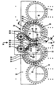
For explalninp the construction of the drive of the first intake and mowing
devices 12 and the cross conveyor element 32, FIG. 4 shows a vertical asctlon
through the header 10 of FIG. 1 t~sken along line 4-4. The second intake and
mowing
devices 14 and cross conveyor element fib from FIGS. 2 and 3 aro thus
equivalent In
teens of construction.
The cutting disk 54, which Is mentioned above, is supported so that it can
rotate above a Lower gear housing 52, which is ripia~yt connected to the
chassis 18. A
first conveyor disk 56 of the intake and mowing device 12 is srrengsd
coaxislly to the
cutting disk 54 and above this disk in the vertical dirHCtion. The cu8inp disk
54 is
driven in operation by a hollow shaft 58, which is provided on its lower end
with gear
teeth 60, which mesh wilfl teeth of a gear 62. The pear 62 is arranged on a
shaft 64,
which la rotatabty mounted in the lower gear housing 52. A first bevel gear 86
is
fixed to a lower region of the shaft 84 and is meshed with a bevel gear 88
fixed to
one end of a drive shaft 70, which is driven by a main drive shah (not shown),
which
is 1n drtve connection with the combustion engine of a self propelled
harvesting
machine, which moves tt~e hiO over a field to be hanr~bE~d.
At a location below the gear 82, the shaft 84 is provided with gear teeth 72
which are meshed with tenth of a pear 74 fixed to a lower region of a drive
shaft 76
which extends through the hollow shaft 58 end the cutting disk 54, end is
rotatebly
supported in the Power gear housing 52_ The shaft 78 cartiaa the ffrat
corweyor disk
58 and sets this in rotation about the rotational a~as 40.
The shaft 76 also drives a first gear 78, which is located in a center gear
housing 80, which is attached above the first conveyor disk 66. The 5rst gear
78
meshes with a second gear 82 defining a lower end of a hollow shaft 84, which
is
14
CA 02474438 2004-07-08
located in the center gear housing 80, rotates about the rotational axis 38,
and drives
a connection disk 88, on whose outer drcumference a kawer conveyor disk 88 and
an upper comreyor disk 90 are located. In ~dit~n, an upper end of the shag 84
defines a third gear 92, which mashes with a fourth sear 84. The fourth gear
94 is
fixed to a second shaft 96 and drives the second (upper) conveyor disk 98 of
the
intake and mowing device 12, which is fhcsd to an upper end of the second
shaft 98.
The third and fourth gars 82, 94 ~ krcabad in an upper gear housir~ 100. which
Is
connected in turn to the center gear housing 80. The shaft 84 is a hollow
shaft and is
mounted for rotation about a fixed support shaft 102, which has opposite ends
respectively pressed within the center gear housing 80 and the upper gear
housing
100 so as to hold there together The gear housing 80 is further supported by
a support 104, which is fixed to and extends outwards and rearvvards in the
radial
direction from the chassis 18 so as to eoctend between the cutting disk 54 and
the
connection disk 86.
The cutting disk 54 and the lower conveyor disk 56, as well as the upper
conveyor disk 98 of the first intalaa and mowing devica 12, are arranged
coaxlally to
each other and to the rotational axle 40. Similarly, the conveyor disks 88 and
90 of
the conveyor element 32 are arrange coaxially to each other and to the
rotattonal
axis 38.
The ratios of the gears y8, 82, 92, and 94 aro selected such that the
conveyor disks 56 and 98 of the first intak~ and mowing device 12 rotate at
the same
speed but faster than the conveyor disks 88 and 90 of the cross conveyor
element
32. However, it would also be conceivable than the oornreyor sped, i.e., the
circumferential speed of the poCkbt-Ilka recesses of the conveyor disks 88 and
90 of
the cross conveyor element 32, could be greater than that of the intake and
mowing
device 12 or be approxtmataly equal.
In another embOdtment, the disk tT~ can bs supported so that It can
rotate on the lower housing 52 and be driven by a gear on its lower side (or a
hollow
shah). Through the cutting disk 54 and the gear or the hollow ahnft, another
hollow
shaft can extend, which is used for driving the conveyor disk 5B and the gear
78.
Another connection element can be arranged in the interior of the other hollow
shaft,
CA 02474438 2004-07-08
which carries the center gear housing 80, so that the support 104 is relieved
of
stress or can be eliminated.
In FIGS. 5-7, other embodiments ofthe invention are shown, wherein
elements that match those of previously described headers aro provided with
the
same reference numerals.
The header 10 in FIG. 5 corresponds essentially to the embodiment shown
in FIO. 2. However, one difference is the addition of a cross conveyor drum
106 in
the wedge-shaped region befinteen the cross conveyor element 60 of the second
intake and mowing device 14 and the cross conveyor element 32 of the first
intake
end mowing device 12. The cross conveyor drums 106 corresspond in construction
and function to the cross conveyor drums from EP 0 760 200 A. They are built
from a
rotational body with an approximately vertical rotational axis, which is
provided vvrth
conveyor disks arranged one above the other with conveyor teeth. The cross
conveyor drums 106 one arranged behind the aoss conveyor channel 34. The
conveyor teeth of its conveyor disks extend through suitable slots in the rear
wall 38,
which delimits rear side of the cross conveyor channel 34. Through suitable
clesrlng
elements (not shown), such as skids or bars, the harvested crops are lifted
from the
cross conveyor elements 50 and received by the conveyor tsetH of the seas
conveyor drums 106, whidl cornrey it fn the direction towards the longitudinal
center
plane 16. Directly downstream of this transfer njgion, the conveyor teeth of
thd cross
conveyor drums 106 also r~eaeive the harvested crops from the second intake
and
mowing devices ~4. Then the cross conveyor element 32 of the first intake and
conveyor device 12 receives the harvested crops from the cross conveyor drum
106.
With the exception of the addition of the previously described cross
conveyor drum 108, the embodiment shown in FIC3. 6 matches that from FIG. 3.
The header 10 shown In FIG. 7 also includes fourth intake and mowing
devices 110. Therefore, a cross conveyor element 112 is allocated to the third
Intake
and mowing devices. In construction, the third intake and mowing devices 48
with
the cross conveyor element 112 correspond In this embcdlment to the second
intake
and mewing devices 14 with the cross conveyor element 50. In the wedge-shaped
region between the cross conveyor element 112 of the third intake and mowing
16
CA 02474438 2004-07-08
device 48 and the cross oonveyar element Sp of the second Intake and mowing
device, a cross conveyor drum 106 is likewis~ amsnged, like that described in
reference to FIG. 5. Another cross conveyor drum 908 is located In the
wedge-shaped rogion between the cross conveyor ebm~s 60 and 32. The
rotational directions of the intake and mowing devices 12, 14, 48, and 110 of
FIG. 7
extend such that in the normal harvsstlng operation, the harvested crops are
cut and
conveyed first in the direction towards the longitudinal center plane 96 of
the header
10. In this way, conveyance problems between Intake and mowing devices
rotating
in opposite senses are eliminated.
For reverse operation, the driven elements of the machine 10 each rotate in
the opposite senses to the described rotational directions.
Having described the preferred embodiment, it will become apparent that
various modlilcatlons can be made without departing from the scope of the
invention
as defined in the accompanying claims.
97