Note: Descriptions are shown in the official language in which they were submitted.
CA 02474617 2004-07-27
WO 03/065798 PCT/SE03/00198
1
INTEGRATED CLOSED LOOP SYSTEM FOR INDUSTRIAL WATER PURIFICATION
DESCRIPTION
Field of the invention
The invention relates to an integrated closed loop system, or a partially
closed loop
system, for water purification, comprising a sequenced bioreactor system for
the
biological processing of nitrogen and phosphorous containing waste water from
a
production process.
Background of the invention
The release of nitrogen and phosphorous compounds into the environment has
become
one of the most pressing environmental hazards. The release is generally of no
significance in low concentrations due to natural presence. However, they are
released in
large quantities especially in industrial, domesticated farm, aquaculture or
forestry
agriculture areas and cause eutrophication of water recipients, first
producing algal
blooms and thereafter oxygen deficiency in natural waters.
Stringent requirements on the processing of biologically produced nutrients
and materials
are one of the limiting constraints for the establishment of new industrial,
food
processing, agro- and aquaculture ventures. This is especially true in parts
of
Scandinavia, and also around the Mediterranean, mid Europe, the US and Canada,
parts
in Oceania, South East Asia, and several developing countries.
This invention focuses on removal of BOD (biological oxygen demand), nitrogen
and
phosphorous by biological means. Numerous biological treatment processes have
been
developed which typically use single or double reactors comprising autotrophic
(ammonia
and nitrite oxidation) and heterotrophic (aerobic organic oxidation and anoxic
denitrification) processes. They are often of a single activated sludge type
or fixed bed
type, using organic matter in the influent for the removal of nitrogen or/and
phosphate
(e.g. WO 96/04784, US 3871999).
The use of activated sludge is cost efficient in large urban waste water
treatment plants.
However, activated sludge is difficult to control (as in high intensive
aquaculture systems
with high rates of recirculation and water flow), due to a necessary
aggregation into flocs
with a subsequent floatation or sedimentation, which are all difficult to
control. It puts
CA 02474617 2004-07-27
WO 03/065798 PCT/SE03/00198
2
requirements on large sedimentation or flotation tanks, which in turn lowers
the cost
efficiency (US 3849303, US 5611927).
Some of the patented innovations in this field are made up of systems that
change the
cycles of purification in one or more reactors over time, sometimes called
sequenced
batch reactor technique (US 4188289, US 4948510). This means that the
microorganisms are subjected to different forms of stress that will lead to
loss of growth
yield and efficiency of the filters or reactors, due to constraints of
metabolic reversals in
each cycle and interspecies competition.
Other disclosures use fixed bed bioreactors. Fixed bed reactors for
purification as well as
any reactor where most of the active biomass is attached as a biological film
on an
immobilized media, are subject to problems with clogging and requirement of
back
flushing of the filter media (US 5081954). Such back flushing removes the
biofilm or
parts of the biofilm, creating a lag phase for the regeneration of full
capacity of the filter.
Furthermore, the uniform distribution of nutrients, oxygen, and carbon through
the filter
is very difficult to control in fixed bed reactors, where a uniform
distribution is actually a
prerequisite for an effective process. Numerous examples on patents disclose
solutions
for an even distribution of water flow in a fixed bed filter, but in practice,
it is impossible
to fully control the even distribution of bacteria, substrate and electron
acceptors as
oxygen or nitrate in the media. More importantly, these constraints impair the
means of
reliable industrial control and optimisation. Fluidised sand bed reactors or
sand or
fluidised bead filters are used to a large extent in the US (e.g. US 5792386).
They claim
high removal rates of BOD and nitrogen. However, the energy input in these
systems is
relatively high since they are driven by high-pressure pumps, whereby cost
efficiency is
lost compared to low head systems, although high pressure systems require
small
footprint area relative to the internal specific filtration area.
In addition, in flow through systems like waste water treatment plants, where
almost all
influent inorganic nitrogen is in the form of ammonium, the water has to be
nitrified
(ammonium is oxidized to nitrite and nitrate) before it is denitrified
(nitrite and nitrate is
reduced to nitrogen gas). In post denitrification systems the denitrification
process is
therefore placed after nitrification reactors (US 3849303, US 5611927). The
denitrification requires an easily biodegradable organic substrate while the
nitrifying
autotrophic bacteria on the other hand, require very low concentrations of
biodegradable
organic substrate to be able to compete with the heterotrophic bacteria.
Therefore, such
systems will fail in either the nitrification process or in the
denitrification process if not a
CA 02474617 2004-07-27
WO 03/065798 PCT/SE03/00198
3
nearly complete degradation of organic matter precedes the nitrification and
an easily
biodegradable hydrocarbon is added to the denitrification process.
Alternatively, one may use predenitrification where the denitrification is put
as the first
reactor constituent in the system (counted from the waste producing process),
e.g. an
activated sludge plant, and the treated waste water is recirculated back to
the
denitrification reactor from a subsequent nitrification reactor after the
water has been
nitrified. In this way the organic matter to be removed is used for the
denitrification
process as well. However, hydraulic limitations of each subprocess in the loop
limit the
recycle and therefore limit the maximum nitrogen removal.
In a closed loop system, where only a small part of the water is exchanged
with the
surrounding environment, the oxidation of organic matter before the
denitrification
process, like in conventional systems and patent disclosures (WO 96/04784),
poses a
reduction in the efficiency of biological water treatment, because available
organic
material that is desirable for the denitrification is lost in the initial
oxidation process. High
efficiency in the nutrient and organic removal is achieved by organising the
biological
processes in the energetically and biochemically most efficient sequence. In
such a
system the natural biodegradable carbon in the production process effluent is
used
optimally if the denitrification process precedes a heterotrophic oxidation
before
nitrification, like in the present invention.
It is the sequence of the biological treatment processes relative to the
production unit
and the inflexibility of the chosen structures that are the major limitations
in disclosures
for water purification. WO 97/49279 discloses one example where the
denitrification is
placed in a recycle after the nitrification, and hence there will be no or
only limited
denitrification if an externally added carbon source is not added. Further,
the hydraulic
load on the entire treatment process will be unnecessarily high. In another
embodiment
in the same patent, where the sequence could be argued to be correct (first a
denitrification process with a by-pass, followed by a carbon filter and
nitrification) the
inflexibility of not having a by-pass over the nitrification process will
imply a very
inefficient use of the nitrification reactor if the nitrite levels are not to
become
dangerously high to many aquatic organisms. Further, the nitrification process
is pursued
in a 4" gravel bed that has the obvious large footprint disadvantage when run
in high
intensive systems. In WO 96/04784 the nitrification is placed first, which
will imply that
there will be almost no nitrification as long as there are biodegradable
organic matter in
the effluent of the production process (fish). The placement of the
denitrification process
CA 02474617 2004-07-27
WO 03/065798 PCT/SE03/00198
4
after the nitrification implies as argued that an external carbon source has
to be added as
well.
The greatest challenge of all in biological water purification processes is
developing
environments for high efficiency of the nitrification process, which is far
more sensitive
than denitrification and BOD-removal. Inefficient nitrification leads to the
production of
nitrite, which may be a great hazard in agro- / industrial processes and
especially if
marine or freshwater animals are produced within the industrial system. Due to
the slow
growth rates of the nitrifying bacteria, these organisms will always be in the
"underdog"
position to other heterotrophic organisms. The main reason for this is that
the nitrifying
bacteria applies the highly energy requiring process of carbon dioxide
fixation by the
Calvin cycle, whereas heterotrophs utilise available organic carbon in
solution for its
anabolism. This main metabolic constraint is followed by the further outlined
growth
limitations of this organism, which is not recognized in patent WO 97/49279.
1. One of the most limiting factors is the need for oxygen for nitrification.
In complete
nitrification 1 g of ammonia requires 4.25-4.33 grams of molecular oxygen. A
rather
low concentration of ammonia of 4 mg / I, thus requires an oxygen
concentration of
17 mg / I, for nitrification to be complete. This oxygen concentration is not
even
present at water temperatures as low as 0°C, where oxygen is present at
14,6 mg / I
in fresh water at normal ambient oxygen partial pressure. At normal process
temperatures around 20°C, as in many indoor industrial processes, water
oxygen
concentrations will not exceed 9 mg / I, at which nitrification will be
incomplete at
ammonia concentrations above 2,65 mg / I. To achieve complete nitrification at
high
ammonium concentrations oxygen has to be dissolved in the water, either by
explicitly adding (aeration or liquid oxygen/air) or passively by having a
large contact
area to the air as in trickling filters, for example.
2. Low ammonia concentrations, lower than 4 mg / I, will lead to reduced
nitrification
rates because the Michaelis-Menten half saturation constant, which is 1-3 mgN-
NHS /
I, causes sub-maximum nitrification rates below levels of 4 mg ammonia / I
water.
Thus, in systems with low ammonia concentrations, nitrification rates are
always sub
optimal. Low ammonia concentrations, around 1-2 mg / I, where the need for
oxygen
is low, thus lead to the concomitant reduction of the nitrification rate to 25-
50% of its
maximum capacity with a corresponding decrease in growth.
3. As long as there is moderate concentrations of biodegradable organic matter
in the
water, the growth of heterotrophs by far outcompete the autotrophic nitrifying
bacteria. In the present invention this problem is over come by placing the
CA 02474617 2004-07-27
WO 03/065798 PCT/SE03/00198
nitrification in a by-pass mode outside the main water stream, to create a
highly
specialized environment for the nitrifying bacteria.
4. High flow rates of water through nitrification reactor usually mean
incomplete
nitrification. Due to low residence time the nitrite oxidizing bacteria will
not be able to
5 oxidize all nitrite into nitrate. This is especially true in systems where
high flow rates
of water are applied and ammonia levels exceeding 4 mg / I As a result toxic
nitrite is
accumulated in the system.
In summary
1. In natural conditions, oxygen levels are usually to low for nitrification
to be complete,
even at very low water temperatures with high oxygen solubility.
2. When ammonia levels are low, lower than 2-3 mg / I oxygen may not be
limiting, but
then instead, the nitrification rate becomes reduced.
3. In the main water stream the nitrifying bacteria are easily out-competed by
heterotrophs, due to high organic load.
4. At high water flows incomplete nitrification will be the result from the
slow growth
rate of the nitrite oxidizing bacteria, compared to the water flow rate.
5. Thus in most cases either oxygen concentration or ammonia concentration is
too low,
or BOD content or water flow is too high. In most cases one of these four
situations
are predominant in the main stream of most continuously operating water
purification
systems. They all result in incomplete nitrification. In WO 97/49279 the
inventors
themselves have provided the evidence of incomplete nitrification with
reported
nitrite levels as high as 15-50 mg nitrite / I for several weeks. At such
levels most fish
species would perish (rainbow trout has LCSO values at 0,03 - 0,06 mg / I).
This is
nowhere better displayed in WO 97/49279 , than when the nitrite levels indeed
drop
abruptly and are reduced to a minimum with the concomitant application of
denitrification in the purification process. Thus, it is clear that the patent
WO
97/49279 has hampered the nitrification capacity in at least one of the
previous four
conditions mentioned above.
Other similar systems, such as DE 38 27 716, have positioned the water
purification
bioreactors out of the mainstream water flow. In this case denitrification is
placed before
nitrification. This has the advantage of consuming BOD in the denitrification
process
before nitrification is applied. But still, water flow leading to the
nitrification reactor will
contain high amounts of organic material that will hamper nitrification, since
no BOD-
oxidising reactors are positioned in-between these two processes. Also, the
water flow
rate leading to the denitrification reactor can support denitrification at
water flow rates
far exceeding the reaction rates of the nitrifying bacteria. In addition, the
purified water
CA 02474617 2004-07-27
WO 03/065798 PCT/SE03/00198
6
is funnelled back to a collection tank and being mixed with incoming non-
purified water.
Naturally, it should be considered a bad management practice to mix non-
purified water
with newly purified. In addition, the bioreactor media is are fixed beds in
both cases,
which contain the limitations, described earlier.
Regarding disclosures of biological phosphorous removal, US 5 380 438
discloses
processing of phosphorous containing water in anoxic and anaerobic conditions
before
applying aerobic phosphorous removal and nitrification in an activated sludge
process.
This invention has the limitation of applying nitrification in the same
reactor as biological
phosphorous removal. It requires competition of PAO (Phosphate Accumulating
Organisms) with the nitrifying bacteria in the same reactor. It is well known
that any
aerobic ammonia containing sludge will develop nitrification in temperatures
and pH
applicable to phosphorus removal. Thus, nitrification bacteria will compete
with the PAO
in this type of reactor. Further, the nitrification produces nitrate that is
known to inhibit
the PAO process and, thus, this system is inherently sub-optimal.
Another phosphorous removal concept makes use of cyclical discharge of
activated
sludge or mixed liquor to three different basins to obtain anaerobic and
aerobic PAO
conditions. The process of US patent 4 948 510 does distinguish between
anaerobic and
aerobic conditions. Furthermore, the competition between nitrifying bacteria
and PAO
accumulation in the aerobic tank is admitted, as well as the competition
between
heterotrophic carbon use and PAO carbon uptake, which are simultaneously
applied. To
solve the problems of competing nitrifying bacteria this invention applies a
rather
complicated 6 (six) cycle system in three different basins. The three
limitations with this
system are:
1. The sludge is always more difficult to control than biofilm processes on
suspended
carriers, especially in combination with aerobic anaerobic processes.
2. The sludge is containing all the microorganisms, nitrifiers, denitrifiers,
aerobic
heterotrophs and PAOs at the same time, exposing them to cyclic changes and
differential metabolic lag phases in the six purification cycles.
3. The microorganisms are forced to compete for the same space, and at times,
same
organic material.
Regarding greenhouse cultivation of plants, one invention defines the
cultivation of water
living animals with photosynthesising water living plants (WO 83/03333). The
water
living plants are living "on land" and are moisturised by water film according
to the
specification. Specifically, the disclosure points out that the water is
purified by
consuming the nitrogen and phosphorous therein. It is known from such trials,
for
CA 02474617 2004-07-27
WO 03/065798 PCT/SE03/00198
7
instance in applying plants for water purification in aquaculture, that a
plant water
purification area of at least 70% of the total production plant area is
needed. Thus, such
a system is not efficient for the water purification itself without extensive
additional water
purification, unless of course the cultured plants are the main production
objective and
the other industrial production units are regarded as by-products (e.g. fish).
High rate closed loop industrial systems or systems for food processing, agro-
or
aquaculture production, with internal processing of BOD, nitrogen and
phosphorous need
to be cost efficient, reliable for control, and easy to operate, with high
turn over rates for
waste in the industrial water treatment. This is not easily obtained with
activated sludge
or high-pressure systems (US 49413510). Among others, high-pressure systems
excerpt
an exceeding bioerosion compared to low-pressure systems. Furthermore, high-
pressure
systems also require above average capital investments.
The present invention is the starting point for an era of low energy,
continuous reactor
and bioreactor system with large filter area and high cost efficiency. It is a
system for the
biological purification of BOD, nitrogen and phosphorous for closed loop
industrial
systems.
Summar~and objects of the invention
The innovation provides an integrated and complete processing system for
industrial and
agricultural waste water; reducing the concentration of BOD or organic
materials;
reducing the concentration of inorganic and organic nitrogen; and reducing the
concentration of organic and inorganic phosphorous compounds by biological
processes.
The system is founded on a sequence of bioreactors in a continuous flow mode,
with
variations on the phosphorous elimination process and optional by-pass systems
for
nitrogen-, phosphorous- and BOD removal. The continuous mainstream design in
the
closed loop represents a water system with the possibility for complete or
near complete
purification of water from the industrial production through filters and
bioreactors before
water exchange is made with the surrounding environment. The array of
sequenced
bioreactors provides constant or nearly constant environments in the
bioreactors, also
producing highly controllable conditions for the microorganisms and thus for
industrial
optimisation.
Description of the present invention
Rather surprisingly, with the present invention it has been found possible to
meet the
highly set demands on water quality in some industrial processes and cultured
species in
agri- or aquaculture. The invention is characterized by an integrated,
partially or wholly
CA 02474617 2004-07-27
WO 03/065798 PCT/SE03/00198
8
closed loop system for waste water treatment, where the water contains
nitrogen
containing compounds and/or substances, comprising at least one production
unit of such
nitrogen containing compounds and/or substances and using continuous
bioreactor
technology for the biological treatment and removal of organic matter,
nitrogen and
phosphorous from the said water at continuous flow, comprising:
a) at least one suspended carrier bioreactor for bacterial growth under anoxic
conditions
to cause anaerobic denitrification, with one or several compartments,
preceding
b) at least one suspended carrier bioreactor for bacterial growth under oxic
conditions to
cause aerobic nitrification,
c) the denitrification taking place after the production unit, and
d) the nitrification taking place prior to the production unit in a by-pass
mode as part of
the continuous flow.
A preferred embodiment of the invention encompasses that part of the
continuous flow is
allowed to pass both the denitrification and the nitrification in a by-pass
mode.
A preferred embodiment of the invention encompasses that one or more oxygen
consumption reactors precede the denitrification reactor, arranged to generate
anoxic
conditions for denitrification.
A further preferred embodiment of the invention encompasses that one or more
particulate removal devices are arranged to generate partially or
substantially particulate
free water in different parts of the system.
A further preferred embodiment of the invention encompasses that the
particulate
removal device is selected from the group consisting of screens, swirl
separators, sand
filters, drum filters, sedimentation tanks, lamella separation filters,
preferably the
particulate removal includes foaming and foam separating devices and skimmers,
for
removal of foam or surface related compounds, as fats-, carbohydrate- and
protein-like
substances, and separate organic material from the water.
A further preferred embodiment the organic material separated at the
particulate
removal system is arranged to be recycled directly to the oxygen consumption
reactor, to
a fermentation reactor or to the denitrification reactor.
Another preferred embodiment of the invention encompasses that one or more
reactors
for oxidation of BOD (biological oxidation demand) or organic material in the
water are
positioned in any favorable position.
CA 02474617 2004-07-27
WO 03/065798 PCT/SE03/00198
9
Another preferred embodiment of the invention encompasses that a screen, swirl
separator, sand filter, drum filter, sedimentation tank or any device for
particulate
removal separates organic material, by skimming or foaming devices from the
water is
arranged in any position in the system.
A further preferred embodiment of the invention encompasses that the organic
material
is arranged to be recycled directly to the oxygen consumption reactor or to
the
denitrification reactor.
A further preferred embodiment of the invention encompasses that the closed
loop
system further contains biological phosphate removal bioreactor placed after a
denitrification and a nitrification reactor.
Another preferred embodiment of the invention encompasses that the closed loop
system
further contains at least one biological phosphate removal bioreactor
containing activated
sludge or suspended carrier system, is applied in any position around
previously
mentioned reactors, in the continuous purification line or in a by-pass
system.
Another preferred embodiment of the invention encompasses that a by-pass
system for a
removal of phosphorous is arranged to use biological activated sludge or a
suspended
carrier system in multiples of anaerobic and aerobic compartment systems.
A further preferred embodiment of the invention encompasses that the activated
sludge
for phosphorous removal is arranged to be recycled via a sedimentation chamber
and
phosphorous is arranged to be expelled by means of sludge.
A further preferred embodiment of the invention encompasses that the
denitrification
reactor contains one or more reactors for oxygen consumption, providing anoxic
conditions for the denitrification system.
Another preferred embodiment of the invention encompasses that a sedimentation
tank
for the final polish of water by chemical precipitation of phosphorous is
placed between
the system and the recipient.
Another preferred embodiment of the invention encompasses that Another
preferred
embodiment of the invention encompasses that a by-pass system is arranged to
make
CA 02474617 2004-07-27
WO 03/065798 PCT/SE03/00198
possible the recycling of the water from the last stage of water purification
after
nitrification or biological phosphate removal, back to the denitrification
reactor or up to
any bioreactor in the purification process.
5 Another preferred embodiment of the invention encompasses that Another
preferred
embodiment of the invention encompasses that a sterilization unit making use
of UV
and/or ozone is placed as the very last constituent of the system, separating
this from
the environment.
10 Another preferred embodiment of the invention encompasses that
sterilization units
making use of UV and/or ozone is placed anywhere in the system.
A further preferred embodiment of the invention encompasses that Another
preferred
embodiment of the invention encompasses that a fermentation reactor is
arranged to
receive dissolved and particulate organic material from particle removal and
foaming
devices.
Another preferred embodiment of the invention encompasses that the organic
material is
arranged to become fermented to fermentation products such as acetic acid or
one to
four carbon carboxylic acids, aldehyds, ketones, acetone or other compounds as
carbon
sources for the reactors, such as methanol, ethanol, glycerol, pyruvate.
A further preferred embodiment of the invention encompasses that Another
preferred
embodiment of the invention encompasses that CO~ is preserved by introducing
oxygen
or pressurized air in a closed BOD oxidation reactor prior to the
nitrification bioreactor.
Another preferred embodiment of the invention encompasses that the
nitrification reactor
is supersaturated with COz by omitting air-and CO~ stripping.
Another preferred embodiment of the invention encompasses that biogas is
arranged to
be produced in the system by fermentation of waste material of the system.
Another preferred embodiment of the invention encompasses that Another
preferred
embodiment of the invention encompasses that oxygen is provided to the system
by any
type of additions, as air, molecular oxygen in gas phase or liquid phase for
any of the
aerobic reactors.
CA 02474617 2004-07-27
WO 03/065798 PCT/SE03/00198
11
Another preferred embodiment of the invention encompasses that oxygen is
removed
from reactors by vacuum, biological respiration or by injecting an inert gas.
Another preferred embodiment of the invention encompasses that the system is
built into
a water conserving building, where ventilation systems recondensate evaporated
water
for energy and water conservation for preservation of water and energy in
cold, tropical
or arid areas.
A further preferred embodiment of the invention encompasses that Another
preferred
embodiment of the invention encompasses that energy is arranged to be
preserved by
use of biogas produced in the system or any other biological system in its
surroundings
based on waste products of the system.
Another preferred embodiment of the invention encompasses that heat is
arranged to be
added by heat pumps, solar radiation, thermal fissures or by external biogas
production.
Another preferred embodiment of the invention encompasses that by-pass systems
are
arranged around all the specific reactor and separator modules in the system
to make
possible differential purification processes and maintenance.
Another preferred embodiment of the invention encompasses that Another
preferred
embodiment of the invention encompasses that artificial intelligence software
programs
are arranged to for the control loops in the steering system, using linear or
dynamic
programming models.
Another preferred embodiment of the invention encompasses that the control
system is
designed for direct operation via the Internet for control and monitoring the
production
optimization and results, as well as modifying control parameters and turn
over rates
according to specific culturing conditions in every production plant of the
here specified
type.
Another preferred embodiment of the invention encompasses that it is
completely or
partially closed with partial purification of the water body, and partial
water exchange
with the surrounding environment.
A further preferred embodiment of the invention encompasses that Another
preferred
embodiment of the invention encompasses that feeding water to plants or algae
for
CA 02474617 2004-07-27
WO 03/065798 PCT/SE03/00198
12
consumption of sulphur, nitrogen and phosphorous as well as mineral salts by
said
aquatic plants and algae.
Another preferred embodiment of the invention encompasses that it encompasses
polishing of the water using aquatic plants consuming nitrogen and phosphorous
prior to
the purification steps, whereby the cultivated plants which are used as feed
for the
species in the aquaculture or food for human use, and/or as an alternative the
basins can
be placed after the purification reactors to improve the water and its quality
to the
species in aquaculture.
Another preferred embodiment of the invention encompasses that it comprises a
plant
and/or algal production system being used in a green house or appropriate
building in an
upper, second level basin, where the depth of the basins is particularly 1 to
10 cm, but
may be up to 1 m deep, i.e., the basin will have a weight of 10 to 2000 kg/mZ,
for the
deeper applications, typically 20-300 kg/mZ.
A further preferred embodiment of the invention encompasses Another preferred
embodiment of the invention encompasses that it comprises plants or algal
growth
systems that filter off red and blue sunlight reducing algae growth in
underlying
aquaculture vessels, filtering off red and blue wavelengths in the range of
420 - 600 nm
and 650 - 720 nm, particularly absorbing light in the wavelengths of 420-550
and 670 -
720 nm.
Another preferred embodiment of the invention encompasses that it comprises
plastic
films for coverage of the light transfer (transmittance) through the windows
of e.g. the
greenhouse, filtering off red and blue wavelengths in the range of 420 - 600
nm and 650
- 720 nm, particularly absorbing light in the wavelengths of 420-550 and 670 -
720 nm.
Another preferred embodiment of the invention encompasses that it comprises an
active
sludge reactor to maximize production of aerobic activated sludge by aerobic
production
and consumption of an essential amount of nutrient salts and BOD before
feeding water
to the remaining reactors.
Another preferred embodiment of the invention encompasses that the active
sludge
reactor is arranged to produce a soil improver, whereby the active sludge
reactor is
placed by means of a by-pass arrangement where the water flow is reduced.
CA 02474617 2004-07-27
WO 03/065798 PCT/SE03/00198
13
Another aspect of the invention encompasses any combinations of one or more
organisms in agri- or aquaculture, cultured in a closed loop system.
Another preferred embodiment of this aspect encompasses any combinations of
one or
more organisms in accordance with above, in which at least one organism is a
fish
species.
Another preferred embodiment of the invention encompasses any combinations of
one or
more organisms in accordance with above, in which at least one organism is a
shellfish
species.
Another preferred embodiment of the invention encompasses any combinations of
one or
more organisms in accordance with above, in which at least one organism is a
crustacean.
As evident from above, it is essential that denitrification, i.e., treatment
of the water
effluent from the production unit(-s) is carried out under anoxic conditions,
before
treatment under oxic or aerobic conditions, i.e. aerobic degradation of
organic matter
and nitrification, whereby elimination of phosphorous preferably takes place
both after
denitrification and nitrification bioreactors, since nitrogen compounds as
ammonia and
nitrate are inhibitory to phosphate accumulating organisms (PAO), ammonia
inducing
nitrification and nitrate being directly inhibitory. Not all water needs to be
treated for
nitrification, but some ammonia containing water can be by-passed directly in
the
mainstream water to the agricultural or industrial processes or species in
aquaculture.
This will lead to an increase in ammonium concentration that is relatively
harmless. Thus,
the level of nitrification outside the mainstream purification, i.e.
nitrification taking place
in mentioned by-pass loop, will need to be dimensioned to counteract an
increase of the
above-mentioned maximum tolerances for ammonium in the industrial system.
Elimination of particulate material from the water should preferably be
carried out before
denitrification, but may also occur after denitrification, depending on the
composition and
fractions of particulates in the effluent water from the industrial
production. In any case,
particulate material is eliminated prior to any nitrification and preferably
prior to the BOD
oxidizing reactor.
Any by-pass flow is carried out based on the condition that concentrations of
e.g.
phosphorous, ammonia, nitrite and suspended solids, are limited to tolerances
with
CA 02474617 2004-07-27
WO 03/065798 PCT/SE03/00198
14
regard to the industrial production system, but maximized in the bioreactor
system for
optimum efficiency.
The industrial process may involve nitrogen limited pulp production,
processing of food
industry water, as from slaughterhouses, diary, brewery, yeast, biotech, blood
processing, agricultural wastes as animal sewage and so forth including
aquaculture.
The term aquaculture is defined as the culture of any fish or shellfish in
fresh-, brackish
or marine waters, or synthetically derived salt formulas for marine water,
such as
culturing of rainbow trout, salmon, yellowfish, cod, sole, turbot, eel, perch,
pike-perch,
pike, crayfish, lobster, Norwegian lobster, prawns, shrimp, oysters, mussels
among
others, including tropical cultured and non-cultured species as milkfish,
tilapia, tropical
salmon species as dourado or Colossoma, catfish species, species of gourami,
perch
species (as e.g. Macquaria), arapaima, snooks or lanternfish, prawns as Yabby
or giant
tiger prawn, etc, just to mention a few. The term fish and shellfish apply
particularly for
food production for human use, or for research purposes, for ornamental fish
and
shellfish production and for production of aquaculture products for use as
fish feed or
shellfish feed.
In the definition of closed loop industrial production systems, all the above
and similar
are included, and there is considered both the complete removal of
biologically generated
solubles that have and may have an ecological impact and the containment of
ecologically undesirable organisms in the industrial unit. These are:
1. Eutrophic substances, such as nutrient salts of nitrogen and phosphorous,
which are
contained and reduced or completely eliminated.
2. Oxygen consuming substances such as organic compounds that can be measured
as
TOC, COD and BOD, i.e. any biodegradable organic substance.
3. Pathogens such as viruses, bacteria and multicellular or acellular
parasites such as
fish lice, flagellates etc.
4. Genetically modified or genetically undesirable strains of different
species of bacteria,
fungi, plants, fish, shellfish or crustaceans present in the industrial
system,
eliminating genetic drift from the production unit to the surrounding
ecosystem.
Loss of water due to evaporation is normally not within the definition of a
closed loop
system, since the loss of water vapour does not lead to environmental penalty.
However,
this system will also be designed for use in arid climates, thence water loss
may be
regarded with penalty and systems containing water from loss due to
evaporation, are
included in the overall plant design.
CA 02474617 2004-07-27
WO 03/065798 PCT/SE03/00198
Excess salts are excreted from the species in aquaculture such as sodium,
potassium,
calcium, magnesium, chlorides and sulphates, etc may be released to the
environment
after sterilisation. The water body is renewed by an external water source or
desalinated
5 after the last steps of purification in the system. If cultivation is made
in any forms,
higher organisms such as parasites and cultured species are not released in
the process
of water exchange.
In overall considerations for phosphate, the removal efficiency may be kept
low or high in
10 the industrial system due to the fact that internal high levels of
phosphate pose no direct
health risk to the species in aquaculture but may pose a hazard in some
industrial
processes. Thus, it is possible and may even be cost efficient to arrange the
phosphorous
removal system as a by-pass system. However, if high levels of phosphate are
kept in
the system, special treatment may have to be made before expelling the water
into an
15 external recipient. Nitrogen free, but phosphate rich water may if
necessary have to be
recirculated through the phosphate reducing reactor several times for complete
or nearly
complete phosphate removal by means of a by-pass system. Alternatively or
additionally,
chemical means may be applied to precipitate the phosphate with salts with
third valence
metal ions, i.e. FeCl3 or AIZ(S04)3, and the phosphate salt finally eliminated
from the
system in any form of a sedimentation chamber. Phosphate removal from the
water to be
purified is enhanced by PAO by first internally accumulating organic materials
under
anaerobic conditions, the organic materials being particularly efficient for
metabolization
if they are any 1-6 carbon compounds in the form of alcohol, ketone, aldehyde,
carboxylic acid forms or generally defined as VOC's (volatile organic
compounds, short
and biologically easily accessible carbon compounds). Secondly, in the aerobic
phase, to
which the anaerobic bacteria are is shifted or submitted to injected oxygen,
phosphate is
accumulated to high levels as inorganic phosphate (Pi) and stored in the form
of
polyphosphate by use of the internally stored carbon incorporated from the
preceding
anaerobic phase. The levels of phosphate storage are in the range of up to 20%
phosphate and 80%, optimally around 50% polyphosphate dry weight of the sludge
or
biomass. The phosphate is ultimately removed as phosphate rich sludge from the
activated sludge sedimentation chamber, or by a washing procedure from which
the
greater part of the activated sludge or biofilm is recycled back or submitted
to the
anaerobic compartment for the next purification round in a phosphate
accumulation
(PAO) process.
In the system the chemical and physical parameters are steered or adjusted in
such a
way that optimal physiological conditions are met for the industrial process
or the
CA 02474617 2004-07-27
WO 03/065798 PCT/SE03/00198
16
organisms that are being cultured. This involves adjustment of parameters as
pH, light,
light duration, light spectrum for growth, light spectrum for growth
inhibition of
undesirable algae, temperature, dissolved oxygen and carbon dioxide, organic-
and
inorganic metabolites, salinity and buffering systems.
The system comprises an industrial production unit, growing tanks,
bioreactors, screens,
particulate separators, pumps, and plumbing, electrical monitoring devices
with sensors,
hard- and software computer controlling systems, electrically or manually
operated
feeding systems for the species in aquaculture and systems for feeding the
micro-
organisms in the bioreactors with substrate for growth. The system can be made
by
different size and shape of the growing tanks, bioreactors, plumbing, pumps
and
monitoring devices, and in any material. Thus, the growth tanks and biofilters
or
bioreactors may be made out of plastic, concrete, steel, stainless steel, or
polymeric
synthetic or organic liners, sea or freshwater netcages or net pens surrounded
or
"bagged" by synthetic or organic liners, or free floating tanks in marine or
freshwater
systems, to which the present innovation of water purification, may be
connected, built
on adjacent floating keys, in floating buoyant tank systems or positioned and
connected
to a land based purification plant containing the here described innovation.
The systems
may be completely closed or partially closed with regard to water exchange
with the
surrounding marine, freshwater or estuarine system. In addition digging
earthen or other
ponds for the culture of species as well as for biofilters may be the basis
for the closed
system. Pumps may be of any number or type including low or high-pressure
water
pumps, centrifugal pumps, air blowers, compressors, airlift driven systems and
stirrers
for gas exchange. In the process of filtering and pumping, the addition of
diffuser
mediated oxygen addition as well as addition of liquid oxygen or other forms
of molecular
oxygen, e.g. pressurized oxygen, air or ozone is included. The system may be
built
indoors, in industrial production units, warehouses or in greenhouses or
placed in the
open land terrain, in freshwater-, river-, estuarine or marine systems,
according to
temperature, humidity and climatologic restrictions and the industrial
production units or
specific requirements by the species in agri- or aquaculture.
The system is comprised by a series of bioreactors, biological filters or
biofilters, the
terms used interchangeably, connected to vessels or tanks for grow-out, brood
stock or
weaning of aquaculture species. The system uses unpressurized fluidised bed
filter
systems with a moving bed or suspended carrier system for the biofilm, with
variations
on carrier material. In addition, a special reactor system may make use of
activated
sludge or suspended carriers for biological phosphorous removal, and as
described, an
additional activated sludge reactor may be used to reduce nutrients and BOD in
the
CA 02474617 2004-07-27
WO 03/065798 PCT/SE03/00198
17
water, before or with a by-pass across the overall central purification
process. The
suspended biological filtration bed will be made of any free-floating material
that acts as
a substrate for the active biological film. Be it plastic materials of
different non-defined
forms, as e.g, plastic scrap material, incinerated (Leca°), zeolites,
alkaline or non-
alkaline sand, lava, wooden or other composite plastic/ceramic composites or
carbon or
polymeric chains. The bioreactor units make use of suspended carriers on which
the
biofilm grows (e.g. using carrier modules like e.g. Biolox, Leca, Bee-cell,
Kaldnaes, Diat,
Etapak, Impodan or Inter Aqua). These carriers can also be of a particular
design made
up of some natural and/or synthetic material (e.g, wooden, carbohydrate, any
type of
carbon polymer such as Teflon, epoxy, hydrocarbon or vinyl carbon products,
polymeric
or plastic scrap products, lava, zeolite, sand, ceramics and any composite of
those
mentioned). In the reactors for phosphorous removal, activated sludge or
suspended
carriers may be used.
The moving bed suspended carrier biological reactor system makes possible the
uniform
distribution of nutrients, oxygen, carbon and redox (reduction-oxidation)
couples by
means of the water flow and/or stirring of the water by different means such
as rotators,
propellers or airlifts. The system requires no chemical processing. However,
as
mentioned under certain conditions, e.g. phosphorous precipitation may be used
as an
additional method for polishing water quality, in any of the water
purification stages.
In all the bioreactors, the surface area for the microorganisms to grow on,
the amount
and balance between carbon, the availability and quality of carbon sources,
including
fermented and inorganic carbon (COQ), mineral nutrients (i.e. N, P, K and
others),
oxygen levels, are regulated for the optimum efficiency of the processes.
These
mentioned levels are a function of the industrial or agricultural production
requirements
or fish, shellfish and crustacean species, feed type and water flow that in
combination
produces the specific array of waste water constituents and concentrations.
The specific
surface area of the suspended carriers is tailor-made and thus adjusted to fit
the biofilm
thickness in every single compartment in the bioreactors according to specific
bacterial
growth conditions as specific growth rate and Michaelis-Menten kinetics of the
limiting
substrate. Thus, decreasing total surface area of the bioreactor suspended
carrier
material or basically increasing biofilm thickness by increasing incoming mass
waste flow.
This creates the possibility to design pocket size bioreactors with high
removal fidelity
with optimal use of reactor volume and footprint space.
The use of low head pumping systems, e.g. airlift pumping of water, makes low
energy
use possible. This also makes possible the design of relatively shallow
bioreactor units
CA 02474617 2004-07-27
WO 03/065798 PCT/SE03/00198
18
and gives a large surface water area on the water table of the bioreactor in
required
cases. This makes possible a relatively large surface area for gas exchange,
e.g. in the
aerobic reactors, which typically can be used where real estate costs are low
or the
suspended filtration material is cheap. Anaerobic reactors, however, do not
benefit from
contact with air and may be made with high relative volume compared to surface
area.
In a special case described below, surface gas exchange or gas stripping from
the water
in the aerobic bioreactors is not desirable, which is the case, when COZ
preservation for
nitrification is required in oxygen-supersaturated water.
Sufficient residence time in the reactors is allowed to allow for sufficient
bacterial growth
and turn over of waste water components for desired purification to occur.
These turn
over rates are well accounted for by data from scientific verifications in
single reactor
set-ups. The levels of oxygen addition by gas exchange systems or concentrated
oxygen
is optimized in regard to the relative BOD, ammonium, nitrate, phosphorous and
nutrient
content associated with the excretion and waste production specific for the
type of agro-
industrial processes. The same principle is applied to adjust the level of BOD
addition to
create anaerobic conditions in the anoxic bioreactors.
Sufficient surface area for the microorganisms to grow on; the amount and
balance
between macronutrients and organic material in general; oxygen levels; and the
availability and quality of carbon sources dictate turnover; flow rates;
hydraulic retention
times; are regulated for the optimum efficiency of the process in each and
every
bioreactor. The specific surface area of the suspended carriers is tailor-made
to fit the
biofilm thickness required in every single compartment in this bioreactor,
according to
the amount of waste loading per unit biofilm area in the bioreactor concerned.
The precise levels of required turn over rate for the bioreactors and
aquaculture system
in general cannot be exactly described in any disclosure. This is due to the
fact that the
balance of nutrients, solids and dissolved organic materials is strongly
dependent on the
type of agro-/ industrial process in the system, at what temperature the
process or
culture is run, at what grow out stage the species are present, and the type
or types of
feed that are used and the manufacturing methods used for production of the
feed, e.g.
extrusion, pelleting, drying or the use of semi moist feed. Particularly, use
of feeds in
agro-/ industrial processes with different manufacturing methods will a// lead
to a
different waste water balance produced in the production vessels, even if the
chemical
elemental composition of these feeds are equivalent. This is a consequence of
the fact
that these processing methods differently affect the biological availability
of feed
components after the processing level in mind, e.g. heating, pelleting, semi
moist feeding
CA 02474617 2004-07-27
WO 03/065798 PCT/SE03/00198
19
or use of dried feed. Thus, pivotally, both the species in the agro-/
industrial system or
system for aquaculture and type of feed in use ultimately dictate what levels
of organic
and nutrient waste will be present in the water system and the distribution of
the waste
constituents, and thus, how to run the most efficient purification mode, turn
over rate,
etc, in the different bioreactors, by the control system.
The by-products from the purification system are:
1. Solid concentrated biological phosphorous sludge, which can be deployed in
agriculture as fertilizer.
2. Non-eutrophic mineral salts are produced, which are sterilised before
release to the
environment as mineral water or retained as a mineral salt after incineration
of
sludge.
3. Fermented organic liquor and/or sediment is produced as a by-product from
fermentation of particulate organic material, which can be used, for soil
improvement
or compost, or reused within the system as BOD to create anoxic conditions.
4. Activated sludge produced as a by-product from the activated sludge
reactor, which
sludge can be used, for soil improvement or compost, or reused within the
system as
BOD to create anoxic conditions.
5. A small amount of sulphuric gas in the form of hydrogen sulphide may be
released to
the atmosphere if not processed internally by gas washing or microbial
oxidation
methods for the production of sulphate.
6. Carbon dioxide (COz) is released from the respiration of the organisms in
the system
and biogas production (which does not add to atmospheric COa increase).
7. Inert dinitrogen gas (NZ) is released to the atmosphere, and may be
released
together with small amounts of nitrous oxide (NZO).
Microorganisms provide the biological conversions in the water system by the
processes
of:
1. Heterotrophic denitrification of nitrate and nitrite, also known as
respiratory
denitrification or dissimilatory denitrification, (by the genera of
Achromobacter,
Acinefobacter, Alcaligenes, Agrobacterium, Aquaspirillum, Azospirillum,
Bacillus,
Bradyrhizobium, Chromobacterium, Corynebacterium, Cytophaga, Flavobacterium,
Gluconobacter, Hyphomicrobium, Kingella, Moraxella, Neisseria, Nitrosomonas,
Paracoccus, Pseudomonas (e.g. P. aeruginosa and P, fluorescens), Rhizobium,
Rhodopseudomonas, Thermofhrix, Thiobacillus, Thiomicrospira, Thiosphaera,
lillolinella, Xanthomonas and the like).
CA 02474617 2004-07-27
WO 03/065798 PCT/SE03/00198
2. Autotrophic oxidation of ammonia and nitrite (by the genera of Nitrosomonas
(e.g.
Nitrosomonas europaea), Nitrosospira and Nitrobacter (e.g. Nitrobacter agilis)
and
the like).
3. Phosphate accumulation of phosphate accumulating organisms (PAO, belonging
to
5 genera Acinetobacter, the proteobacteria, Cytophaga, Flavobacterium and the
like,
the high mole G+C gram positive bacteria, and specifically, bacteria
identified by all
variants of the EUB and HGC molecular gene probes and their linked genetical
relatives).
4. Heterotrophic oxidation of organic materials (by all heterotrophic genera
of bacteria
10 and fungi including e.g. the genera Achromobacter, Acinetobacter,
Alcaligenes,
Agrobacterium, Aquaspirillum, Azospirillum, Bacillus, Bradyrhizobium,
Chromobacterium, Corynebacterium, Cytophaga, Flavobacterium, Gluconobacter,
Hyphomicrobium, Kingella, Moraxella, Neisseria, Nitrosomonas, Paracoccus,
Pseudomonas, Rhizobium, Rhodopseudomonas, Thermothrix, Thiobacillus,
15 Thiomicrospira, Thiosphaera, Wolinella, ~Canthomonas and the like).
5. Mineralisation of nitrogen, phosphorous and other biologically/organically
incorporated nutrient salts, primarily by all here mentioned heterothrophs,
and
finally,
6. Methanogenesis and fermentation (by the strict anaerobic methanogens, the
20 autotrophic methanogens, the homoacetogenic bacteria, including the genera
Acetobacterium and the Archaic methanogens by the genera of Methanobacterium,
Methan~brevibacter, Methanococeoides, Methanococcus, Methanocorpuseulum,
Methanoculleus, Methanogenium, Methanohalobium, Methanohalophilus,
Methanolobus, Methanomicrobium, Methanoplanus, Methanopyrus, Methanosaeta,
Methanosarcina, Methanosphaera, Methan~sprillum, Methanothermus, Methanothrix
and the like, including fermentative microorganisms such as fungi (e.g, yeast
Saccaromyces) and any non-pathogenic forms of bacteria like Acetobacter,
Acetobacterium, Acetivibrio, Acetoanaerobium, Acetogenium, Acetitomaculum,
Bacteroides, Citrobacter, Clostridium, Deslufotomaculum, enteric bacteria like
Escherichia, Enterobacter, Eubacterium, Gluconobacter, Klebsiella,
Lactobacillus,
Leuconostoc, Malonomonas, Oxalobacter, Pelobacter, Propionibacterium,
Propionigenium, Proteus, Pseudomonas, Salmonella, Shigella, Sporomusa,
Streptococcus, Zymomonas, the autotrophic homoacetogenic bacteria, autotrophic
sulphate reducing bacteria, acetic acid bacteria and the like) and other
fermenters
which produce fermentation products from particulate organic material stored
in a
fermentation reactor (as e.g. acetate, 2-alkyl-acetate, acetone, benzoate, 2,3-
butanediol, butanol, butyrate, caproate, ethanol, formate, glycerate,
glycolate,
hydrogen gas, lactate, malate, methane, phosphoenolpyruvate, propionate,
pyruvate,
CA 02474617 2004-07-27
WO 03/065798 PCT/SE03/00198
21
succinate, and their derivatives, or other fermentation products produced by
the
involvement of acetyl-CoA, propionyl-CoA, butyryl-CoA, succinyl-CoA,
acetylphosphate, butrylphosphate, ~,3-bisphosphoglycerate, carbamyl phosphate,
adenosine-phosphosulphate (APS), glycerol, nucleotide derivatives, all
biological or
synthetically derived aminoacids, their peptides or protein and protein
complexes,
sugars as hexoses, pentoses or riboses, and carbohydrates in general,
carboxylic
acids or fatty acids like lauric, myristic, palmitic, stearic, oleic,
linoleic, a-linoleic fatty
acids, derived in saturated or non-saturated forms in any number of carbon
atoms
attached to their chains in any combination, or alcohols, aldehydes, alkanes,
amines,
enols, ethers, leetones, thiols, and their alkylic derivatives, phenols,
aromatic amines
and any of the derivatives of the here mentioned substances participating in
any
bacterial metabolic conversion).
The fermentation products are used as a carbon source for the bioreactors and
also
produce methane as an additional source of energy. Thus, the system provides
endogenous carbon from the waste water for denitrification and phosphate
removal as
well as for energy production. For full biological optimisation, external
synthetic or
biologically derived carbon compounds may be added (such as methanol, ethanol,
molasses, acetate, butyrate, propionate, sugars, carboxylic acids, poly-fi-
hydroxybutyrate (PHB), or any of the fermentation products and their
derivatives of the
above mentioned).
In addition nitrification and denitrification may simultaneously be carried
out by the
Anammox process in which oxidation of ammonia is connected directly to
denitrification.
The organisms participating in these reactions of this process have not yet
been
elucidated.
In addition to the biological processes, numerous processes for separation of
particulate
material, such as mechanized particulate removal, sedimentation tanks, sand
filters or
centrifugation devices (like lamella separators, drum filters (e.g.
Hydrotech°), swirl
separators, triangle filters, or disc separators for particulate removal) may
be used,
including bead filters, fluidised sand filters, this includes foaming and foam
separating
devices and skimmers, for removal of foam or surface related compounds, as fat-
,
carbohydrate- and protein-like substances.
Numerous air or molecular oxygen addition methods, addition of ozone, UV
filtrations are
employed for the optimization of water quality. Especially, UV-filtration and
or ozone may
be employed before release of mineral rich, but nutrient low or nutrient
absent exchange
CA 02474617 2004-07-27
WO 03/065798 PCT/SE03/00198
22
water from the closed loop water body, for the sterilisation of the water
before reaching
an external recipient.
Water exchange, in combination with salt addition, may be used to set salt
concentrations to preferred levels, which may include alkalinity controlling
buffer salts.
Water may be heated by solar radiation. Temperatures may be set and controlled
at any
minimum temperature for different culturing requirements, by water exchange,
ventilation heat exchangers, and any type of heat pump system or biogas.
Pumps may be driven by wind, sludge incinerationt or biogas generated
electricity.
The following central themes of the sequenced bioreactor system is that the
system
makes use of denitrification before the BOD oxidation and nitrification
processes, and
that an increase of biological purification efficiency in many cases can be
further
increased by a multiple loop system. This makes possible:
1. Substantial conservation of organic carbon for denitrification.
2. Reduction of organic materials before the nitrification process that in
turn increases
the nitrification efficiency.
3. The increase of concentration of ammonium, nitrate, BOD and phosphate in
any
reactor loops for increase of biological purification efficiency, with the
combination of
at least one internal loop systems within the water purification.
4. Decrease of water flow during the purification process, which in turn
increases
biological purification efficiency, since the hydraulic retention time can be
increased.
5. Repeated recirculation of waste water within the loop or bioreactor, thus
increasing
the purification efficiency by repeated exposure to the microorganisms in the
purification reactor, is made possible by internal by-pass-systems in the loop
systems
or bioreactors.
Thus the basic considerations are that purification operations and by-pass
flow
combinations are such that concentrations in the water are maximized in one or
more
loops which then increases purification yields in the reactors. Concentrations
in
mentioned loops may be maximized up to bet well below the tolerances of LCso-
values
(lethal concentration where 50% mortal rate is executed) for the aquaculture
organism
cultured, which produce the main following waste constituents: NH~+/NH3, NO~ ,
P0~3-,
their inorganically bound analogues and BOD and TSS in general.
CA 02474617 2004-07-27
WO 03/065798 PCT/SE03/00198
23
Brief description of the drawings
FIG. 1 represents a basic embodiment of the invention.
FIG. 2 represents a schematic view of a bioreactor sequence in detail.
FIG. 3 represents a schematic view of one embodiment of a bioreactor sequence
of the
invention, and
Serial and successive compartments of the bioreactor in question will increase
the
efficiency of each bioreactor in the system in many cases. Thus, in most
cases, the
bioreactors are designated a, b, c, and so forth, for each successive
compartment in the
same biological reactor process. This compartmentalisation is an arrangement
that is
tailor-made according to the above-mentioned amount and balance of nutrients
and
carbon produced by the specific type of agro-/ industrial system in mind. The
compartmentalisation of any one specific bioreactor in the system may be made
within
one or by arrangement of several successive separate tanks.
Detailed descr~tion of the invention
The basic aspect of the invention is the use of internally produced organic
material or
BOD from the production unit for the denitrification and phosphorous
accumulation in a
bioreactor system, preferably comprising a suspended carrier system and or
activated
sludge reactors, respectively. This basic aspect leads to the reduction of
organic
materials, which lead to the increased efficiency of nitrification. The
process involves the
following basic and successive purification steps:
1. Oxygen reduction by internal use of BOD or by BOD addition.
2. The reduction of nitrite and nitrate by denitrification to atmospheric
molecular
nitrogen.
3. Oxidation of organic material or BOD for reduction of organic waste in the
water.
4. Autotrophic oxidation of ammonium-nitrogen to nitrate.
5. Biological phosphorous elimination with PAO's.
6. The water is recirculated back to the agro-/ industrial production unit.
7. Finally the oxidised nitrate-nitrogen is returned to the denitrification
reactor for final
reduction to molecular NZ-nitrogen after one cycle through the aquaculture
tanks.
The invention will be described in detail with reference to FIG. 2, which
shows one
embodiment of the invention. In all the figures the same numerals are applied,
10
denotes one or multiples of industrial production units or production units
for agri- and
aquaculture in multiples of culturing tanks or vessels, wherein the fish,
shellfish or
crustaceans or other organisms to be cultured develop, grow and is fed;
arrowed lines
drawn in full black are connecting the different bioreactors of the system for
water
CA 02474617 2004-07-27
WO 03/065798 PCT/SE03/00198
24
purification; dot-dashed lines indicate particulate organic material transport
separated
from the water flow; dotted lines indicate optional loops for transport of
fermentation
products following the biological processes; dashed lines indicate system
pathways in use
during water exchange, i.e. loop RN and loop RP. Arrows at the lines indicate
the
direction of the flow of water or mass transfers.
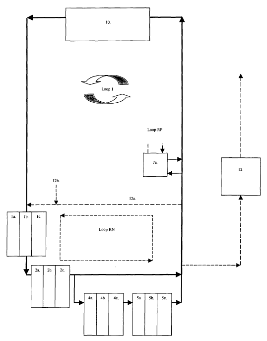
In FIG 1 a basic embodiment of the invention is outlined.
In general terms the waste water flow from the production unit 10. The first
net
purification process starts with reactor 1, which is an oxygen consumption
reactor in
loop 1, reducing oxygen concentration levels to a minimum. The water then
reaches a
denitrification reactor 2 to produce gaseous nitrogen (Nz) from any nitrite
and nitrate in
the water. After denitrification water is divided in a by-pass to form loop 2,
where BOD
oxidation takes place in reactor 4 before nitrification in bioreactor 5. Thus,
loop 2
separates the nitrification reactor from the rest of the water system and
represents a
highly specialized water environment with low organic levels favouring
autotrophic
growth; largely differing from the effluent waste water produced from the
production
vessels 10, the denitrification vessel 2 and thus positioning nitrification as
far away as
possible from the mainstream water flow. After nitrification, phosphorous,
when obtained
in a concentration suitable for phosphorous removal, is removed in a
bioreactor 7, before
water is redirected back to the production unit 10. A loop RN is a
recirculation loop for
nitrogen (N) purification and water exchange preparation, running through by-
pass
system 12a, before water to the water exchange tank 12 is discarded from the
system.
Water refill to the system is made by valve 12b. The loop RP represents a
recirculation
loop for repeated phosphorous treatments in reactor 7.
In FIG 2 a further detailed embodiment of the invention is outlined
In general terms the waste water flow from the production unit 10 first passes
one or
more reactors 3, wherein particulate material is removed and/or foaming
devices and/or
skimmers are applied, for removal of foam or surface related compounds, before
it enters
a reactor 1, which may be divided into more compartments or consist of more
reactors
la-1c, etc. Prior to reactor 1 a by-pass separates a loop 0 from loop 1. In
loop 0, no
processing of nitrogen or phosphorous is made, hence the designation of "loop
0", and
water is recirculated back to the production unit 10 with minor water quality
adjustments
made to fit basic requirements for the production unit, such as BOD oxidation
in reactors
4, which may be executed in different positions in loop 0. The first net
purification
process starts with reactor 1 in loop 1, which is an oxygen consumption
reactor,
reducing oxygen concentration levels to a minimum. The water then reaches a
denitrification reactor 2, 2a-c, etc, to produce gaseous nitrogen (NZ) from
any nitrite and
CA 02474617 2004-07-27
WO 03/065798 PCT/SE03/00198
nitrate in the water. Further particulate separation ensues in reactor 3,
before it reaches
a BOD oxidation reactor 4, 4a-4c, etc, in loop 1 whereby reactors 1, 2, 3 and
4 together
with a reactor 11 form loop 1. Reactor 11, may be positioned in several
positions and
represents a gas-stripping reactor, primarily eliminating COZ, in the water
that is directed
5 back to the production unit 10. A by-pass separates water in loop 1 from a
third loop:
loop 2, which contains the nitrification reactor 5, where nitrification takes
place (i.e.
wherein ammonia and nitrite are oxidised to nitrate), and a BOD eliminating
reactor 4
prior to the nitrification reactor 5. Thus, loop 2 separates the nitrification
reactor from
the rest of the water system and represents a highly specialized water
environment.
10 After nitrification, phosphorous, when obtained in a concentration suitable
for phosphor-
ous removal, is removed in a bioreactor 7a, before water is recirculated to
the production
unit 10. As is later explained nitrification 5 and denitrification 6 b precede
the biological
phosphorous removal reactor containing the PAO. A loop RN is a recirculation
loop for
nitrogen (N) purification and water exchange preparation, running through by-
pass
15 system 12a, before water to the water exchange tank 12 is discarded. A loop
RP
represents a recirculation loop for repeated phosphorous treatments in reactor
7.
The detailed descriptions of the processes are described as follows in FIG. 2.
Before the
first biological purification step of the waste water funnelled from the
production unit(-s)
20 10, particle removal devices in the form of screen, swirl separator, sand
filter, drum fil-
ter, sedimentation tank or any device for particulate removal 3, including
bead filters,
fluidised sand filters, including foaming and foam separating devices and
skimmers, for
removal of foam or surface related compounds, as fats-, carbohydrate- and
protein-like
substances, separate organic material from the water. Particle removal devices
3 may
25 also be placed directly in the culture tanks in the form of a sediment
trap, lamella or
screen type separator. The particulate separation in this purification step
ranges between
approximately 10 to <100% of suspended solids, depending on the type of
separation
process, energy input and screen mesh. Screen mesh range is in the area around
10-500
pm, typically between 20-140 pm, particularly 60 pm (t 20 pm). Lamella
separators, if
used, are applied at the sedimentation velocity range of 0,1 - 5 m/h and with
an inclina-
tion of the lamellas in the range of 10 - 80°, particularly 45°
(~15°). Size of sand par-
ticles in the sand filter range from 100 - 0,1 mm, particularly 1-10 mm, and
may be of
any naturally occurring mineral composition, sand or gravel, including
alkaline sediments,
and may act as a buffering component for the water system. As noted in the
detailed
outline, particle separation devices 3 may be placed in several places in loop
0, 1 and 2.
An example of the placements of particle removing devices 3b and 3c is that
water flow
in these positions is reduced compared to the prior position of device 3a. A
particularly
advantageous position 3c is accomplished since this position removes excess
particles
CA 02474617 2004-07-27
WO 03/065798 PCT/SE03/00198
26
before "burning off" of BOD in reactor 4, leading to sufficient reduction in
BOD levels in
loop 2, where nitrification ensues, the latter demanding low BOD levels for
high efficien-
cy. One possible position for the reactor is in position 3d, which may be
executed if e.g.
the BOD oxidation reactor 4 in loop 1 is substituted with BOD oxidation
reactor 4 in loop
0.
The separated particulate organic material from devices 3 is stored and
fermented in a
fermentation reactor 9, or in part or directly transported into a
denitrification reactor 2
via the dot-dashed route (not all connections are drawn) and/or an oxygen
consumption
reactor 1. The fermenting reactor has organic or sediment turn over rates of 5-
30 days,
typically 10-25 days, particularly 15 days (t 3 days) of organic sludge age.
The pH levels
are to be run between 5 and 8.
Synthetic or otherwise enriched or biologically produced obtainable organic
material may
be added as a biological energy source via the fermentation reactor 9 or
directly into any
reactor via the dotted or dot-dashed route and may be of any carbon compound
earlier
described, particularly to the oxygen consumption reactor 1 or 6a, and
denitrification
reactor 2 or 6b.
In the first biological step, in an oxygen consumption reactor 1, oxygen in
the incoming
water from the culture tanks 10, via the particle separation units 3, is
removed either by
degassing with nitrogen, or another inert gas, or by addition of a carbon
source with con-
comitant microbial oxygen consumption. The reduction of oxygen to lower
threshold
levels for the production of microbial anaerobic/anoxic conditions is
especially necessary
for the induction of denitrification, but also for phosphorous removal in a
later step 7a, b
or c. Reactor 1 may make use of especially fast respiring micro organisms
(e.g. Azoto-
bacter or other metabolically or genetically related species in multiple
organism com-
munities involving both fungi and bacteria). General rates of oxygen
consumption range
between 1-50 mg O~/mZ h, depending oxygen saturation levels, the quality of
the organic
material and biofilm thickness. Common oxygen consumption rates may lie in the
range
of 1 - 10, or even as narrow as 2-7 mg 0~/mz h.
Nitrogenous gases may be diverted directly from the anoxic bioreactor 2 to the
reactor 1
for oxygen degassing of incoming water to reactors 1 and 2.
In the second step, denitrification removes nitrate and nitrite from the water
body in an
anoxic bioreactor 2, by its final biological reduction to inert molecular N~-
nitrogen that is
released to the atmosphere. Of special importance is the control of the C/N
ratio in the
CA 02474617 2004-07-27
WO 03/065798 PCT/SE03/00198
27
incoming water to the bioreactor, so as to provide it with enough carbon for
the present
nitrate to be reduced. The approximate range of carbon utilisation in this
process lies in
the range of 1-10 kg organic material (with these figures defined in the form
of BOD or
COD) per kg of reduced nitrate-nitrogen. For instance, the reduction of
nitrate with
methanol requires around 1.9 kg of methanol per kg of reduced nitrogen-
nitrate. The use
of acetic acid for denitrification will require 2.67 kg of the substance per
kg of nitrogen-
nitrate reduced. Redefining methanol and acetic acid as BOD, will require 2.87
and 2.85
kg of methanol and acetic acid respectively, calculated as BOD. However, these
are
examples of high-grade carbon substrates, not readily available in excessive
amounts in
aquaculture water, and more importantly, expensive. Thus using low grade
carbon
resources as fermented sludge, molasses or silage liquor or the like, may
require higher
levels of carbon source due to higher conversion ratios, and may reach far
above the 3
kg BOD level, or even 5 kg and above, for the reduction of one kg of nitrogen-
nitrate.
Denitrification is an obligate anaerobic process and the threshold levels of
oxygen for
enzymatic activity lie in the area of 0,2 - 0,3 pg O~/I. Such low levels are
desirable, but
not always imperative for denitrification systems in practice. This is due to
the fact that
the oxygen content in the water body may be significantly higher than in the
biofilm. The
biofilm may still provide for anoxic or anaerobic conditions at far higher
bulk concentra-
tions of oxygen. In practice, denitrification may occur at reasonably high
rates at bulk
water concentrations as high as 0.5 mg0z/I. Thus, the actual thickness of the
biofilm in
the denitrification reactor will be a significant determinant for the needed
reduction of
water oxygen concentrations in the water, to acquire desired levels of
denitrification.
The feeding of BOD to the preceding bioreactor 1 regulates these levels.
General rates
for denitrification range between 0.2 and 40 mg N/m2 d, depending on the
anaerobic
completeness, the quality of the organic material and biofilm thickness.
Common
denitrification rates lie in the range of 0.5-5, particularly 1.5-3 mg N/m~ d.
In the third step, particle separation devices 3 separate organic material
from the water
in device 3c, accordingly to the detailed description above. The organic
material is re-
directed to the fermentation reactor 9, or directly to the oxygen consumption
reactor 1
or the denitrification reactor 2. Thus, the total organic content in the water
is lowered
before an ammonia and nitrite oxidation ensues in bioreactor 5 in loop 2. This
particu-
late carbon elimination may be an optional stage, depending on the overall
quality of the
water for purification, i.e. the balance between macronutrients and organic
material in
general. This device may be placed after or preferably before (3c) a BOD
oxidizing
reactor 4, in the next step in positions 3c or 3d.
CA 02474617 2004-07-27
WO 03/065798 PCT/SE03/00198
28
In the fourth step, in reactor 4, the prime concern is the oxidation of
dissolved organic
material (BOD). In this reactor, high oxygen levels reduce BOD content by
aerobic
oxidation. When there are reasons to keep the levels of toxic nitrite at close
to zero
concentration none of the BOD oxidising reactors, except the ones in the
nitrification
stream, should be run to the onset of nitrification, nitrification being
especially unde-
sirable in loop 0, where it could produce toxic nitrite directly expelled into
the production
unit 10. The efficiency of nitrification in the following nitrification
reactor 5 is directly
connected to the BOD removal efficiency, nitrification being strongly limited
by organic
matter or BOD content in water. Since nitrifying microorganisms are
autotrophic and slow
growing, they will typically be out-competed by heterotrophic microorganisms
at certain
BOD levels. High levels of BOD lead to heterotrophs overgrowing the
autotrophic nitri-
fying bacteria, which reduces substrate availability of both ammonium and
oxygen for the
nitrifying bacteria. BOD may be added to the foregoing bioreactors 1 and 2 but
only in
part consumed. Thus, BOD has to be oxidised before reaching the bioreactor for
nitri-
fication, for which purpose this BOD oxidising reactor 4 is installed. It is
practically im-
possible to remove all available BOD. However, consumption of BOD has to be
maxi-
mised in this part of the system before reaching the nitrification reactor. In
a similar
respect BOD consumption leads to the reduction of BOD levels in the water
leading back
from reactor 4 to the production unit 10 in the by-pass loop 1 and 0. In
overall conside-
ration, the level of BOD concentration where nitrification becomes limited is
very variable
biodegradability, oxygen concentration and temperature. Typically at oxygen
saturated
water at high temperatures, e.g. at 28°C, BOD becomes limiting for
nitrification as BOD
levels rise above between 10 and 94 mg/I. At temperatures of 15-20°C
nitrification can
be limited by a BOD concentration as low as 5 mg BOD/I in oxygen saturated
water. An
average value for BOD concentration limitation for nitrification at
20°C lies around 20 mg
BOD/I. Typically substandard environments develop where high diffusion rates
of small
carbon compounds (VOC's) are present, and negative factors impairing diffusion
of
oxygen prevail, like in low oxygen concentrations in the biofilm or thick
biofilms. Such
substandard conditions are common, not to say prevailing, in e.g. most
agricultural or
fish farming systems where effluent water is funnelled directly to the
nitrification filter
from the culture tanks. BOD consumption is effectively enhanced by bacteria
with the
high respiratory rates (e.g. Azotobacter or other metabolically or genetically
related
species) and multiple organism communities involving both fungi and bacteria,
which
then more readily compete for and consume the different fractions of carbon
available as
BOD in this step. Optimisation is made by addition of any source of oxygen in
this part of
the system. General rates of BOD oxidation range between 1-50 mg BOD/m~ d,
depending oxygen concentration in the bulk water , the quality of the organic
material
CA 02474617 2004-07-27
WO 03/065798 PCT/SE03/00198
29
and biofilm thickness. Common oxygen consumption rates may lie in the range of
2-30,
particularly 7-15 mg BOD/m~ d.
The fifth step, which may be present in loop 1 or in loop 2, is the oxidation
of ammonia
to nitrite and further to nitrate in reactor 5. Since nitrite is very toxic to
aquatic organ-
isms, the nitrification process has to convert essentially all compounds that
are oxidised
into nitrite, completely to nitrate. However, complete nitrification is rare,
even in super-
saturated conditions, due to competition with heterotrophic bacteria and BOD
residues.
Optimisation is made by addition of any source of oxygen in this part of the
system and
by control of the retention time in the reactor. Blowing in air can make up
oxygen
addition, or oxygen enriched air, liquid oxygen injection, or concentrated
oxygen gas
(molecular oxygen, O~), into the reactor to support the aerobic oxidation to
nitrate.
Oxygen and ammonium are generally the limiting substrates for nitrification,
whereas
BOD has an indirect inhibitory effect. However, at high ammonium levels,
supersatura-
ting the water with oxygen may also lead to limitation of CO~ for autotrophic
growth. This
may occur especially at low pH levels, when access to COZ is very poor, due
poor car-
bonate buffering system holding very little carbon dioxide in the system. Thus
even if an
ideal maximum kinetic nitrification level at 20°C of around 100 mg NH4+-
N / mZ h or
below (at maximum Michaelis-Menten kinetics), only requires around 1.2 - 1.4
mg COz /
mZ h, the water concentration of CO~ is only around 0.6 mg/I in water (in
equilibrium
with the atmosphere), as e.g. is the case in all trickling filters. In normal
cases in such a
system, COz concentrations are not limiting, due to excess COZ produced by
hetero-
trophic bacteria. However, it can be demonstrated that at oxygen saturation
levels in
water at 20°C (9.08 mg Oz/I), oxygen is limiting for nitrification if
ammonium concen-
trations are above levels of 2.14 mg/I, which is a low level for ammonium. It
can be
demonstrated that at normal conditions in high rate aquaculture systems, where
am-
monium concentrations may welt accumulate to the level of 10 mg/I, as in eel
farms
(concentrations of above 70 mg NH4+ have been verified during normal
operation),
indeed CO~ is limiting for nitrification provided that oxygen is in excess by
supersatura-
tion. In general, under natural conditions in aquaculture systems, oxygen is
normally the
limiting factor. Thus, for maximum efficiency, i.e. providing enough CO~ under
supersatu-
rated oxygen conditions, the preservation of COa in reactors 1, 2, 3, 4 and 5
by avoiding
gas stripping, de-airing and/or hermetically closing the reactors for loss of
CO~ is applied.
In these cases an efficient way of injecting oxygen may be in liquid or
gaseous phase of
OZ. Hereby COZ can be preserved in the water phase without need for gas
stripping,
which then provides enough CO~ and OZ, in supersaturated conditions. This
variation of
nitrification, especially when confined to loop 2, may be very cost efficient,
since loop 2
has the lowest water flow in the system the addition of molecular oxygen may
be used to
CA 02474617 2004-07-27
WO 03/065798 PCT/SE03/00198
create such conditions of supersaturated oxygen. This then requires a minimum
amount
of molecular oxygen addition to achieve super-saturation and above-standard
nitrification
rates. In oxygen supersaturated conditions, some nitrification rates have been
found to
exceed maximum ambient nitrification rates by a factor of 17. Further, and
even more
5 important in some cases, this arrangement allows the aquaculture system to
be run at
"low" pH levels of 5.5 to 6.5, or even lower, which reduces the content of
ammonia to
the advantage of higher ammonium concentrations. Thus, preservation of carbon
dioxide
together with high oxygen levels maintains the nitrification efficiency, even
with poorly
functioning carbonate systems at these pH values. General nitrification rates
range
10 between 1-100 mg N/m~ h, depending oxygen saturation levels, ammonia
concentra-
tions, pH, BOD levels and biofilm thickness. In these cases bi,ofilm thickness
varies from
10 - 1000 Vim, typically being 50 - 500 pm thick, specifically around 200 pm
(t100 pm).
Common nitrification rates in non-saturated environments with negative
influence of BOD
may lie in the range of 0.2-6, particularly 2-4 mg N/mz h. However, depending
on the
15 optimisation of nitrification levels the rates may increase by 10 to 20-
fold in conditions
with supersaturated O~- and CO~-gas levels.
After nitrification in reactor 5, water is either funnelled back to the
production vessels
10, together with denitrified water from loop 1, or it is partly treated for
biological
20 phosphorous removal in reactor 6 and 7.
On the way back from loop 1 and 2, water may undergo additional treatments.
Water
from loop 1 and 0 typically con~ains high levels of carbon dioxide (COQ) and
may have to
be stripped from gases produced in the previous reactors 1, 2, 3 and 4. This
is done in a
25 gas-stripping unit 11, which may be placed in loop 0 and/or loop 1. In
addition, water
coming directly from production vessel 10 may be heavily laden with CO~ and
BOD, thus
a BOD oxidising reactor 4 may have to be inserted in the mainstream water flow
in loop
0.
30 Alternatively, stripping of harmful gases may be unnecessary if a plant or
algal produc-
tion basin 19 or 20, containing macrophytes or algae reduce nutrient and COz
content for
production of oxygen. Additionally, basin 21 may be an activated sludge basin
for partial
reduction of nutrients and the production of soil improver organic material,
placed before
or after the inlet of plant production unit 20, and before or after the
particle separation
unit 3a. The associated macrophytes in the plant production units may be of
the genera
of Elodea, Egeria, Cabomba, Myriophyllum, Ceratophyllum, Eleocharis,
Potamogeton,
Limnophila, or Vallisneria, Ludwigia, Nasturtium, Hydrocotyle, Oenanthe and
genetically
(genotypic) or functionally (phenotypic) related species. A large important
group of water
CA 02474617 2004-07-27
WO 03/065798 PCT/SE03/00198
31
plants for such culture belong to the Bryophyta with taxonomic classes of
Hepaticae and
Musci, specifically of the genera Fontinalis, Vesicularia and Sphagnum. Among
these
species it has been shown that some species, e.g. Myriophyllum, produce up to
50 g dry
weight mz / day. In natural stands its average biomass is usually in the range
500-700 g
dry weight/m2. In cultivation, with an artificial stem support, some of these
species can
attain a positive growth rate even at high densities, and a biomass
corresponding to
around 2000 g dry weight/m~. Furthermore, it can be grown well in a broad
range of
nitrogen concentrations, its biomass production staying approximately the same
through
the range 20-140 mg/I of nitrogen in water, which are relevant levels for
aquaculture
waste production of nitrogen. Also coexistence assay results show that
macrophytes of
the genera of Cabomba and Myriophyllum have inhibitory effects; producing
growth-
inhibiting allelopathic compounds are continuously secreted to inhibit
undesirable blue-
green algae (e.g. Microcystis aeruginosa, Anabaena flos-aquae, or Phormidium
tenue)
undesirable in most water systems. Of special interest is the cultivation of
the water
surface plant duckweed and their genetically (genotypic) or functionally
(phenotypic)
related species of the genera of Lemna, Spirodela, INolffia and VIlolffiella,
divided on at
least 17 known species. Other such functionally related species are from the
genera and
families (in brackets) of Eichhornia (Pontederiaceae), Pistia (Araceae),
Salvinia (Salvini-
deae), Azolla (Azollaceae) and Victoria (Nymphaeaceae). Some of these plants
show
unusually high productivity. Average weight increases of 2-20 g / m~ d has
been verified
for Lemna. Doubling times in the range of 24 hr have been observed on many
occasions,
and a production rate of 64 g/g dry weight/week, or 73 tons/ha/yr. Analysis
suggest that
production is positively influenced by the concentration of organic compounds
in the
water, making ideal as a component for purification of water directly obtained
from
industrial systems with high BOD content. Ammonium concentration in the range
of 20-
60 mg/I NHS+-N has no negative effect on duckweed production. In pond for
clarification
around 20% percent of the pond these plants can remove influent nitrogen.
The sixth step is the by-pass arrangement and preparation step for biological
phospho-
rows accumulation and removal in reactor 7. This mode of operation has the
advantage
of making possible the continuous water exchange by releasing water from 7a,
7ca or
7cb to the subsequent aerobic BOD oxidation tank 4, to be finally expelled.
The PAO
process is negatively influenced by the presence of nitrate and in additional
need of short
volatile organic carbon chains (VOC's). Thus, the phosphate accumulation
process in
reactor 7 is negatively influenced by denitrification because denitrification
removes
carbon necessary for phosphate accumulating organisms, PAO's. The presence of
nitrate
also inhibits polyphosphate storage. Thus, nitrate should be consumed before
phosphate
accumulation and denitrifying microorganisms and PAO's should not compete
about the
CA 02474617 2004-07-27
WO 03/065798 PCT/SE03/00198
32
same carbon source. Also, in high temperatures, above 10°C, the
presence of reduced
nitrate compounds, as ammonium will develop a nitrifying activated sludge or
biofilm.
Thus, low levels both of nitrate and ammonium, together with high levels of
VOC's should
be present in the water to be treated by PAO's. For these reasons, one
optional mode of
operation is to install the phosphorous removal system after nitrification
tank 5, as the
PAO reactor 7a. The reason being that no ammonium, or only low levels of the
sub-
stance, will be present after nitrification in reactor 5, hence only
denitrification is needed
for removal of the remaining nitrate. Oxygen reducing reactor 6a is thus used
after
reactor 5 and before PAO reactor 7a, to produce anaerobic/anoxic conditions
before
transfer to reactor 6b for denitrification. After transfer to the PAO reactor
7a, the first
PAO cycle starts with the addition of fermentation products (VOC's),
preferable from the
fermentation reactor 9, for carbon accumulation in PAO. The second cycle for
PAO's
ensues when transfer is made to the aerobic PAO reactor 7b. Here, the
biological
purification process is finalized by the accumulation of phosphorous in the
PAO by
internal storage of phosphorous under aerobic conditions. (It is hereby noted
that all the
PAO reactor alternatives mentioned can be designed with or without both an
aerobic or
anaerobic compartment, illustrated only with examples 7ca and 7cb in FIG 2.)
In
summary, for the operation of bioreactor 7a, two additional reactor steps,
oxygen
consumption 6a and denitrification 6b, are needed before the completion of the
water
purification process in the PAO reactor 7a, since the presence of the
preceding nitri-
fication reactor 5 in this step, already has reduced ammonium content in the
water. If
the PAO system is designed as an activated sludge system, recycling of the
sludge is
made through the RP-loop.
In contrast, installing the PAO by-pass system after the denitrification
reactor 2 in loop
1, reactor 7b, would require four reactor steps before reaching the PAO
reactor 7b,
which are 6c and 6d respectively 6a and 6b. The reason for this is that the
waste water,
after the denitrification reactor 2, is an anaerobic, ammonium and BOD
containing water.
Thus, BOD oxidation (6c) must precede nitrification (6d) to nitrify for
oxidation of
ammonium after which an anaerobic deoxyfication reactor 6a, analogous to 1,
needs to
consume oxygen to produce anoxic conditions, and finally denitrification (6b)
is needed
for the final consumption of nitrate. The water is then free of/or containing
very low
levels of, ammonium and nitrate and is prepared for the PAO reactor 7b. But
clearly, in
this set-up costs may be doubled compared to set-up in reactor 7a, due to the
need of
additional arrangements for nitrogen removal, requiring approximately four
reactors in
contrast to two reactors in the previously mentioned reactor 7a.
CA 02474617 2004-07-27
WO 03/065798 PCT/SE03/00198
33
An optional and best mode of operation with the PAO system, depending on
tolerances
for phosphorous by the species in aquaculture and constraints put on the
system by the
precipitation side effects of phosphorous, may be its set-up with a PAO
reactor 7c. In this
arrangement the PAO reactor will be arranged outside the recycle loop (loop
RN), thus no
phosphorous elimination is made in the standard recycling and purification of
mainstream
water in the aquaculture system. Thus, in this embodiment, harmless
phosphorous will
accumulate in the aquaculture system. In this case, the PAO system is only
reducing
phosphorous as water exchange is made in the aquaculture system as a whole. In
reac-
tor 7c the PAO reactor will receive its water via the water exchange tank 12,
as water is
moved out of the aquaculture system for exchange. However, this puts certain
con-
straints on the PAO system. Water exchange must be made at least once every 48
hours,
otherwise the PAO population biofilm or sludge in any of the reactors 7a-c,
will decline in
numbers in competition with other microorganisms, the other organisms then
competing
for other substrates available when phosphorous is reduced to low
concentrations. Thus,
prolonged sub-concentrations of phosphorous in reactor 7c will lead to the
decline of PAO
sludge or biofilm. Preferably water exchange is made every 6 hours, typically
every 3 -
12 hours, the water exchange commences at the latest 12 hours after feeding,
typically
3-12 hours, preferably 1-6 hours after the arrest of waste production, or
after the arrest
of waste production after feeding in agri- aquaculture systems. After this
arrest of waste
production after feeding, the reactor purification system in loop 1 and 2,
will have lower-
ed concentrations of nitrate and ammonia to below average concentrations in
loop 0, 1
and 2, making water ideal for PAO treatment and release to an external
recipient. How-
ever, before this is done, the loop RN (the nitrogen recycle loop) polishes
off remaining
waste products inherent in the reactor system-loop 1 and 2, particularly
ammonium and
nitrate, to a minimum before being expelled to the water exchange tank 12. As
water is
released to tank 12, the refill valve 12b, is opened to fill the system with
fresh external
water without mixing with the water being expelled. This mode of operation has
the
advantage of water exchange being made as the waste production has halted,
thus as
loop RN polishes off the water, preparing it for release to tank 12, loop 0
temporarily
works as a closed system. However, the levels of waste in production unit in
loop 0 will
only accumulate slowly, since waste production peak or peak after feeding has
been
passed, and thus the temporarily closed loop RN can be run without hazards for
the
species in aquaculture. Alternatively when industrial production is haltered
in the pro-
duction unit 10. As nitrogen levels have been optimally lowered by
recirculation through
by-pass 12a, water is finally discarded to the water exchange tank 12, as
simultaneously
the water inlet 12b is opened for substitution of the discarded water. A last
important
feature in reactor 7a-c is a RP loop (the phosphorous recycle loop). This loop
provides
the possibility for internal recycling of water containing too high levels of
phosphorous to
CA 02474617 2004-07-27
WO 03/065798 PCT/SE03/00198
34
be released to the environment or aquaculture system. In the RP loop, excess
phos-
phorous is recycled back trough the PAO reactor for repeated treatments, for
reduction to
very low phosphorous levels, before release. Evidently, set-up using reactor
7c as the
PAO unit, requires no additional "auxiliary" nitrification and denitrification
reactors as in
reactors 7a and 7b. Thus, this must be regarded as the most cost efficient and
advanced
solution for biological phosphorous elimination in aquaculture systems.
The subsequent reactor steps prepare the water for the "final clinical"
quality, when re-
quired, before being expelled to the environment. An optional BOD-oxidizing
reactor 4 at
this level polishes off remaining BOD previously added for efficient PAO
reactor treat-
ment. Thus, reactor 4 lowers the BOD levels to very low levels, not higher
than 10 mg /
I, preferably 1 - 5 mg / I, typically lower than 1 mg BOD / I.
Reactor 15 designates UV-treatment equipment for the sterilization of the
water, which
alternatively or together with ozone may be added to the process in reactor
15, which in
some cases may alleviate the need for the previous BOD reactor 4, since ozone
reduces
BOD in treated water. Ozone also sterilizes the water.
Next step represents the stage where the water has been purified from
biologically active
nutrients as nitrogen and phosphorous compounds, including BOD. Viruses,
bacteria and
parasites up to macro fauna and flora level (as nematodes and fungi), have
been
destroyed by the sterilization treatment 15. As a measure of security, after
the function
of the sterilization units 15, which can be disrupted by electrical short-
circuits or
electrical failures, an autoclave 16 is administered. This autoclave is filled
batch-wise as
water exchange is made. If an electrical failure should occur, potential
pathogens will be
contained in this autoclave. The autoclave can be filled, even during
electrical failures,
with UV-filter or ozone inactive, and finally, as electricity is again
available, the autoclave
is run at least at 100°C and a pressure of 1.01 kg/cm2, typically at
121°C and a pressure
of 1.1/cm2 kg for the complete sterilization of all organisms in that water.
The water is
now germ free.
Finally the water may be desalinised in reactor 17 for use as drinking water,
expelled to
the environment or, depending on climate, a g in arid areas, been flushed back
into the
aquaculture system for reuse.
Different forms of by-pass around bioreactors, pumps, electrical monitoring
devices with
sensors, UV-units, fermentation units, culturing tanks, sedimentation and
screening units
are applied for all units in the processing of water. In the drawing, only one
example of a
CA 02474617 2004-07-27
WO 03/065798 PCT/SE03/00198
by-pass is given 18. But this by-pass system is applied around each and every
bioreactor
and particle separator for water processing and maintenance purposes.
The steering system of the production system is made by the Integrated Process
Control
5 System (IPCS), monitoring and controlling the aquaculture production and
filtration
bioreactors. Artificial intelligence software programs control the control
loops in the
steering system, using linear or dynamic programming models. The control
system is
design for direct operation via the Internet to control and monitor the
production
optimization and results, as well as modifying control parameters, according
to specific
10 culturing conditions.
In order to determine the purification needs, primarily, a number of computer
simula-
tions were run to establish data for the construction of a plant for culturing
fish.
15 The accuracy of the culturing operations will improve as a number of
culturing operations
have taken place, as all data will be stored in data bank, which data are then
considered
at further operations, thereby improving growth, yield and feedstuff
efficiency, as well as
heat supplies, water losses and other parameters of interest.
20 Data from simulations
This is an illustration of how water quality can be estimated with aid of the
simulator,
knowing biological parameters of the type of fish being cultivated and
parameters
regarding the food fed to the fish. The simulation considers a fictitious fish
species in
freshwater, since the actual species is of less importance since the
biological purification
25 processes function regardless of fish species.
The following parameters regarding fish, feed and water result in a specific
water quality
after simulating two months of operating.
30 Fish
Initial bodyweight10 g
Final weight 3000 g
Production 6 months
cycle
Production 420 kg/month
CA 02474617 2004-07-27
WO 03/065798 PCT/SE03/00198
36
Feed
Proteins 44.0
Fat 24.0
Carbon hydrates14.0
Ash 8.0
Water 10.0
Water
Temperature 15C
Volume 160 m3
Flow 500 m3/day
Water exchange0.4
Plant
The simulated plant consists of 14 fish tanks, 6 m3 each, together with a
biological waste
water treatment stage.
The biological treatment stage consists of 3 anaerobic operating tanks each
with a
volume of 10 m3 and four aerobically operating tanks, one of 7.5 m3 and three
of 10 m3.
Moreover the biological treatment stage also consists of a particle trap in
form of a sand
filter.
Running the simulator with fish, feed and water specified as above results in
the
following water quality in the fish tanks, with respect to 16 key substances.
CA 02474617 2004-07-27
WO 03/065798 PCT/SE03/00198
37
Water quality after operating one month.
Notation Description Unit
SI Inert soluble organic material 44.0 gCOD/m3
SS Readily biodegradable substrate 5.35 gCOD/m3
XI Inert particulate organic material0.43 gCOD/m3
XS Slowly biodegradable substrate 2.38 gCOD/m3
XBH Active heterotrophic biomass 3.34 gCOD/m3
XBA Active autotrophic biomass 5.74e-04 gCOD/m3
XP Particulate products from biomass 1.24 gCOD/m3
decay
So Dissolved oxygen 4.97 g02/m3
SNO Nitrate and nitrite nitrogen 1.34 gN/m3
SNH Ammonium and ammonia nitrogen 2.15 gN/m3
SNP Soluble biodegradable organic nitrogen1.13 gN/m3
XNp Particulate biodegradable organic 0.49 gN/m3
nitrogen
SAi~ Alkalinity (as HC03-equivalents) 2.11 Mole/m3
Sco~ Dissolved carbon dioxide 8.42 g/m3
SP Phosphorus - -
TSS Total solid substance 5.78 g/m3
This is an illustration of how water quality can be estimated with the aid of
the simulator,
knowing biological parameters of the type of fish being cultivated and
parameters
regarding the food fed to the fish. The data and constants used in the system
are
retrieved from scientific papers, produced from some of the leading scientist
in water
science and technology, as may be seen from the reference list.