Note: Descriptions are shown in the official language in which they were submitted.
CA 02474804 2009-11-05
ROPE TIGHTENING DEVICE FOR SPACE DEFINING NETTINGS OF THREE-
DIMENSIONAL FRAMEWORKS
The present invention relates to a rope tightening device for space defining
nettings
of three-dimensional frameworks. The space defining nettings is stabilized by
means
of supporting frames, wherein rope parts are connected to junction point
members of
the supporting frame.
Space defining nettings made up of rope nettings and combined with variable
supporting frame systems have turned out to be particularly successful
elements in
the designing of playgrounds. By using these space defining nettings, various
playing
environments can be created in connection with three-dimensional structures,
thus
promoting children's physical exercise.
The space defining nettings made up of interconnected ropes are tightened
within a
predetermined supporting frame system wherein a high degree of flexibility of
the
supporting frames can be achieved by interconnecting individual supporting
frame
rods by means of spherical hollow bodies, thus being able to create many
interesting
geometrical shapes. The space defining nettings are then attached and
tightened
within said supporting frames by attaching them to the spherical hollow bodies
and
rods.
Thus, for the purpose of tightening the space defining nettings, it is known
to press
the rope ends to form eyelets and connect them individually or in groups by
means of
shackles via a tightening screw to the spherical hollow bodies, i.e. the so-
called
junction point members of the outer supporting frame structure where they are
tightened. The proper tightening of the nettings is necessary in order to
prevent the
ropes from fraying out at their attachment and crossing points.
On the one hand, the method of attaching and tightening the space defining
nettings
by means of shackles and tightening screws can result, in the worst case, in
playing
children getting caught, mostly with their fingers, in the openings and gaps
which
emerge in the eyelets, between the ropes, and in the attachment elements. On
the
other hand, this method of attachment, due to the inevitable structural length
of the
used elements, results in the loss of space at the supporting frame which
could
1
CA 02474804 2009-11-05
otherwise be used for playing. Moreover, this way of attachment is optically
unsuitable for a device which children use for playing.
It is therefore the object of the present invention to propose a rope
tightening device
for space defining nettings used by children for playing which is practically
invisible in
the playing areas within said three-dimensional frameworks, thus being able to
avoid
the risk of injuries without affecting the tightening of the nettings.
This object is achieved by providing a rope receiving part which is arranged
by
means of a tightening screw on a surface of a junction point member. The rope
receiving part is movable in the direction of the tightening motion. The rope
parts of
the space defining netting are fixable within the rope receiving part.
Advantageous
embodiments include a rope receiving part shaped as a spherical-cap which
comprises a spherical retaining cap with a hollow-cylindrical sidewall. The
spherical
retaining cap may be concave or convex or plain. The spherical retaining cap
may
also comprise side slots. The spherical retaining cap may also comprise an
axial
bore with an internal thread in which the axial bore and the tightening screw
are
arranged. The axial bore is extended by means of an adapter sleeve. The
spherical
retaining cap may also comprise internal slots. A covering disk is connected
to a
screw head of the tightening screw. Also, a tension plate and a tension nut
are
arranged on the external thread of the tightening screw.
The spherical-cap shaped rope receiving part is coverable by means of a
covering
cap which is arranged on the tightening screw. The compact rope receiving part
is
configured as a compact, moulded solid part. The compact rope receiving part
comprises recesses. The axial bore of the compact rope receiving part
comprises an
internal thread. The tightening screw comprises a guide pin which is guided in
a pin
bore in the wall of the junction point member. The tightening screw is
supported by
means of an internal guide which is attached to the inner surface of the
hollow
junction point member. The compact rope receiving part may also include side
slots.
The compact rope receiving part comprises internal slots which are configured
as
bores if necessary. The flanged sleeves are inserted into the rope openings of
the
wall of the junction point member. The rope part of the rope comprises a
retaining
part in addition to the enlargement. In the event the junction point member is
2
CA 02474804 2009-11-05
configured as a solid body, the tightening screw is only screwably arranged in
the
screw bore.
Thus, there is indicated a rope tightening device for space defining nettings
of a
three-dimensional framework wherein rope parts of the space defining nettings
are
connected to the junction point members of a supporting frame to which frame
the
space defining netting is attached, the rope tightening device according to
the
present invention being characterized in that a rope receiving part is
arranged, by
means of a tightening screw, on an inner surface or an outer surface of a
hollow
junction point member or on an outer surface of a solid junction point member,
respectively, wherein said rope receiving part is movable in the direction of
the
tightening motion, and that the rope parts of the space defining netting which
is to be
tightened are fixable within the rope receiving part.
In a preferred embodiment of the rope tightening device according to the
present
invention, a spherical-cap shaped rope receiving part comprises, according to
the
present invention, a spherical retaining cap with a hollow-cylindrical side
wall. The
spherical retaining cap is concave or convex or plain. The spatial surface
design of
the spherical retaining cap particularly depends on the required direction of
the
tightening motion in connection with the design of the outer and inner
surfaces,
respectively, of the junction point member. The compact rope receiving part
comprises at least one side slot where a rope part comprising an enlargement
can be
inserted and fixed. The arrangement of multiple side slots provides the
possibility of
fixing multiple enlarged rope ends. An internal thread of an axial bore in the
spherical
retaining cap of the spherical-cap shaped rope receiving part enables a
tightening
screw to be screwed in. The rope tightening device can be placed in the hollow
junction point member. Advantageously, a partially spherical retaining cap of
the
spherical-cap shaped rope receiving part is provided in connection with a
spherical
junction point member. The rope parts of the space defining netting are put
through
bores in the wall of the junction point member and fixed in the side slots of
the
compact rope receiving part. The fixed rope parts are tightened in a direction
opposite to the screwing direction by means of the tightening screw which can
be
screwed against the inner surface of the junction point member in a preferred
embodiment of the tightening device. The enlargements of the rope parts can be
attached in a manner which is known per se.
3
CA 02474804 2009-11-05
In another advantageous embodiment, the rope tightening device is arranged on
the
outside of the hollow junction point member. In this embodiment, the slots are
configured as internal slots on the spherical retaining cap. Said slots
provide the
possibility of fixing both rope parts with enlargements and continuous ropes.
By
means of a covering disk which is connected to the head of the tightening
screw or
inserted into a corresponding bore, the internal slots are covered to such an
extent
that the rope parts or the continuous ropes, respectively, are prevented from
slipping
out. Here, the tightening screw is screwed with its external thread into a
corresponding bore in the wall of the hollow junction point member. The fixed
rope
parts or continuous ropes, respectively, can now be tightened inside the
junction
point member to the required extent by means of a tension nut and a tension
plate,
said tension plate being pressed against the inner surface of the hollow
junction point
member.
In one embodiment of the present invention, the spherical-cap shaped rope
receiving
part arranged on the outside can be covered on its open side by means of a
covering
cap. This embodiment is particularly suitable in situations in which the use
of a
particularly long tightening screw is required for technical reasons and the
occurrence
of injury-causing openings in the side receiving part must be prevented.
In another advantageous embodiment of the rope tightening device according to
the
present invention, a rope receiving part is configured as a compact, moulded
solid
rope receiving part. This configuration of the rope receiving part has turned
out to be
particularly advantageous at the occurrence of particularly high tension
forces. For
the purpose of adaptation to the shape of the respective junction point
member, the
outer surfaces of the rope receiving part can be concave or convex or plain.
For the
purpose of providing a particularly secure attachment of the rope parts in the
rope
receiving part, the side slots as well as the internal slots comprise recesses
which
receive the enlargements of the rope. The axial bore of the compact rope
receiving
part can comprise a thread in which the tightening screw, for the purpose of
tightening the ropes, can be screwed in or out, respectively. In this
connection, there
are advantageously provided a guide pin of the tightening screw, said guide
pin being
supported in a pin bore and in a retaining plate, and an internal guide of the
4
CA 02474804 2009-11-05
tightening screw in the event of the junction point member being configured as
a
hollow body. The internal slots of the rope receiving part can be configured
as bores.
It has turned out to be suitable to insert flanged sleeves into the rope
openings of the
wall of the hollow junction point member after inserting the enlarged rope
parts, said
flanged sleeves being adapted to reduce the distance between the rope and the
wall
of the rope opening and, in addition to that, to prevent the rope from being
damaged
by avoiding contact between the rope and the edges of the rope openings.
In order to prevent the enlarged rope parts from slackening in the rope
receiving part,
another embodiment of the present invention provides an additional retaining
part by
means of which a further enlargement of the rope part is achieved.
In the embodiment providing a solid-body junction point member, the tightening
screw is only screwably arranged in the screw bore. The depth of the screw
bore is
defined by the size of the solid layer.
The invention will now be described in greater detail with reference to the
accompanying drawings in which:
Fig. I is a diagrammatic section of a rope tightening device arranged inside
the
hollow junction point member;
Fig. 2 is a diagrammatic top view of the rope tightening device arranged
inside the
hollow junction point member;
Fig. 3 is a diagrammatic perspective view of a rope tightening device arranged
outside the hollow junction point member;
Fig. 4 is a diagrammatic section of a rope tightening device arranged outside
the
junction point member;
Fig. 5 is a diagrammatic perspective view of a rope tightening device which
fits tightly
to the junction point member;
5
CA 02474804 2009-11-05
Fig. 6 is a diagrammatic section of a rope tightening device arranged outside
the
junction point member, said rope tightening device comprising an additional
covering
cap;
Fig. 7 is a diagrammatic view of a covering disk of the rope tightening device
arranged outside the junction point member;
Fig. 8 is a diagrammatic section of a rope tightening device arranged outside
the
junction point member, said rope tightening device comprising enlarged rope
parts;
Fig. 9 is a diagrammatic section of the arrangement of a single-piece rope
receiving
part;
Fig. 10 is a diagrammatic section of the arrangement of the rope parts in
recesses;
Fig. 11 is a diagrammatic top view of a single-piece rope receiving part
comprising
recesses;
Fig. 12 is a diagrammatic section of the arrangement of a flanged sleeve in
the wall
of a junction point member;
Fig. 13 is a diagrammatic view of an enlarged rope part comprising a retaining
part;
Fig. 14 is a diagrammatic top view of a compact rope receiving part with
additional
retaining parts; and
Fig. 15 is a diagrammatic section of a solid junction point member comprising
a
tightening screw inserted therein.
The following exemplary descriptions with reference to the drawings serve to
illustrate the embodiments of the rope tightening device according to the
present
invention.
6
CA 02474804 2009-11-05
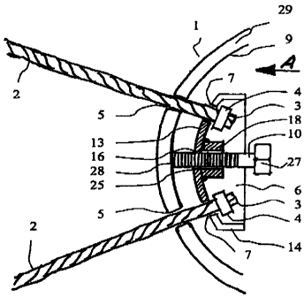
Fig. 1 indicates a hollow junction point member 1. Circular or slot-shaped
rope
openings 5 are provided in a wall 29 of the junction point member 1. Ropes 2
are
inserted into the rope openings 5. The ropes 2 are fixed at rope parts 3 in a
spherical-
cap shaped rope receiving part 6, said rope parts comprising enlargements 4.
The
enlargements 4 of the rope parts 3 prevent the rope parts from slipping out of
side
slots 7 arranged in a side wall 14 and in a spherical retaining cap 13 of the
spherical-
cap shaped rope receiving part 6.
Fig. 2 shows the exemplary configuration of the side slots 7 in the spherical
retaining
cap 13 of the spherical-cap shaped rope receiving part 6. A tightening screw
10 can
be screwed into an axial bore 16 comprising an internal thread 25. The axial
bore 16
comprising an internal thread 25 can be extended by means of an adapter sleeve
18,
if necessary. The screw tip 28 of the tightening screw 10 can be screwed
against an
inner surface 9 of the hollow junction point member by means of a hexagon
screw
head 27 whereby the rope receiving part 6 is moved in a direction opposite to
the
moving direction of the bolt, i.e. toward the centre of the junction point
member 1. As
a result of this, the ropes 2 are tightened because they are clamped in the
side slots
7 due to the enlargements 4 of the rope parts 3.
Fig. 3 illustrates a rope tightening device according to the present invention
which is
arranged outside the hollow junction point member 1. This perspective view
shows
that the tightening screw 10 is inserted into a screw bore 15 in the wall 29
of the
hollow junction point member 1. Four ropes 2 are fixed in the spherical-cap
shaped
rope receiving part 6 by means of a covering disk 11.
Fig. 4 is a diagrammatic section of the rope tightening device arranged on the
outer
surface 8 of the hollow junction point member 1. The wall 29 of the junction
point
member 1 comprises the screw bore 15 through which the tightening screw 10 is
inserted into the inside of the junction point member 1. A continuous rope 2
is
arranged within the spherical-cap shaped rope receiving part 6. For this
purpose, it
was necessary according to the present invention to provide internal slots 24
in the
spherical retaining cap 13 of the spherical-cap shaped rope receiving part 6.
Fig. 7
illustrates the shape and the arrangement of the internal slots 24.
7
CA 02474804 2009-11-05
For the purpose of preventing the inserted rope 2 from slackening, there is
provided,
according to the present invention, the covering disk 11 which covers a part
of the
slots 24 in such a way that the rope 2 cannot slacken. The covering disk 11 is
connected to the screw head 27 of the tightening screw 10. Inside the junction
point
member 1, a tension plate 12 and a tension nut 21 are arranged on the external
thread 17 of the tightening screw 10, said plate and nut being separated from
each
other by means of a washer 23. By means of the tension nut 21, the spherical-
cap
shaped rope receiving part 6 can be pressed tightly onto the outer surface 8
of the
junction point member 1, thereby tightening the rope 2.
Fig. 5 shows the spherical-cap shaped rope receiving part 6 which fits tightly
to the
outer surface 8 of the junction point member 1.
Fig. 6 shows an exemplary arrangement of an extended tightening screw 10. This
arrangement requires the spherical-cap shaped rope receiving part 6 to be
covered
by means of a covering cap 20 and a covering cap nut 22.
Fig. 8 shows the possibility of fixing rope parts 3 by means of special
enlargements 4
in the event of the rope tightening device being attached to the outer surface
8 of the
hollow junction point member 1. While the upper rope part has been enlarged by
means of an arrangement which is known per se, the lower rope part 3 is
provided
with a clamping sleeve 26 which comprises an internal thread into which an
adjusting
screw 19 with a washer 23 can be screwed. Again, the tightening screw 10 is
fixed in
the internal slot 24 by means of the covering disk 11. The adjusting screw 19
can be
used for further tightening of the rope.
Fig. 9 is a diagrammatic view of an exemplary arrangement of the tightening
device
according to the present invention with a compact, solid rope receiving part
6a. The
tightening device according to the present invention is arranged inside the
hollow
junction point member 1. An internal guide 31 is attached to the inner surface
9 of the
junction point member 1. The internal guide 31 guides the tightening screw 10
which
is screwably arranged in the axial bore 16 of the compact rope receiving part
6a. The
tightening screw 10 is further guided by means of a guide pin 32 in a pin bore
38. The
tightening screw 10 is accessible via a junction point member opening 30. When
the
8
CA 02474804 2009-11-05
tightening screw 10 is screwed into the axial bore 16, the tightening screw 10
presses
against the tension plate 12, thus moving the compact rope receiving part 6a
in the
direction of the tightening motion, thereby tightening the rope 2.
The rope parts 3 with the enlargements 4 are fixed in recesses 33.
The diagrammatic section of Fig. 10 and the diagrammatic top view of Fig. 11
show
in detail how the rope parts 3 are fixed in the recesses 33.
The detail in Fig. 12 shows the arrangement of a flanged sleeve 34 in the rope
opening 5 of the wall 29. The inner diameter of the rope opening 5
approximately
corresponds to the diameter of the enlargement 4 of the rope part 3 which
enables
the enlargement 4 to be pushed through the rope opening 5. Afterwards, the
rope
opening 5 is closed by means of the flanged sleeve 34 which is pressed into
the rope
opening 5. At the same time, this arrangement avoids disadvantageous contact
with
the wall 29.
The details in Fig. 13 and Fig. 14 representing another advantageous
embodiment of
the present invention show the use of a retaining part 35 which can be used in
addition to the rope enlargement 4 of the rope part 3. This arrangement is
particularly
advantageous when the diameter of the internal slots 24, which here are
configured
as bores, approximately corresponds to the diameter of the enlargement 4. By
means
of the retaining part 35, the rope parts 3 can be fixed on the compact rope
receiving
part 6a after inserting the rope parts 3 with the enlargement 4 into the
internal slots
24.
Fig. 15 shows a solid junction point member 1. By means of a tightening screw
10, a
rope receiving part 6 is screwed into a screw bore 15 of the junction point
member 1
in such a way that the rope 2 can be tightened. Fig. 15 also shows the
arrangement
of a supporting frame rod 37 on the junction point member 1 which rod is
attached to
the junction point member 1 by means of a screwed joint 36.
9
CA 02474804 2009-11-05
List of reference numerals
1 - junction point member
2 -rope
3 - rope part
4 - enlargement
- rope opening
6 - spherical-cap shaped rope receiving part
6a - compact rope receiving part
7 - side slot
8 - outer surface
9 - inner surface
- tightening screw
11 - covering disk
12 - tension plate
13 - spherical retaining cap
14 - side wall
- screw bore
16 - axial bore
17 - external thread
18 - adapter sleeve
19 - adjusting screw
- covering cap
21 - tension nut
22 - covering cap nut
23 - washer
24 - internal slots
- internal thread
26 - clamping sleeve
27 - screw head
28 - screw tip
29 - wall
- junction point member opening
31 - internal guide
CA 02474804 2009-11-05
32 - guide pin
33 - recess
34 - flanged sleeve
35 - retaining part
36 - screwed joint
37 - supporting frame rod
38 - pin bore
11