Note: Descriptions are shown in the official language in which they were submitted.
CA 02474941 2004-08-06
FLAMELESS BOILER
FIELD OF THE INVENTION
The present invention relates to a flameless system for boiling water and,
more
particularly to a flameless boiler in which heat for heating the water comes
primarily from
the energy produced by a prime mover which may be the engine of the tractor
transporting the boiler.
BACKGROUND OF THE INVENTION
In a drilling operation, steam is required throughout the drilling process and
in
maintenance operations after drilling has finished. Present systems generally
use a
conventional boiler housed in a boiler building to generate and supply the
steam.
Because conventional boilers use an open combustion process, the boiler
building must
be located at least 26 metres from the wellhead. This presents the
disadvantage that
the footprint of the lease site must be enlarged accordingly and more tubing
is required
to bring the steam to the well bore with attendant thermal losses.
Open combustion boilers have a number of additional disadvantages. The open
flame
is less controlled compared to the use of a flameless system which derives
heat from the
energy produced by an internal combustion engine. Exhaust gases are often
hotter in
an open combustion system and if they are not monitored these systems can
flood and
expel flame. The temperatures in these systems can reach instantaneous
temperatures
greater than the kindling temperature of natural gas. This means that if there
were a
natural gas leak, the danger of explosive combustion is present. A diesel or
propane
leak in the vicinity of the burner can also be ignited.
Further, the combustion process in an open flame system is not as complete as
in
enclosed systems, which can produce free radicals that escape into the
atmosphere.
_1_
CA 02474941 2004-08-06
Closed combustion systems have compression ratios commonly many times greater
than open combustion burners. This lack of compression negatively affects the
reactiveness of oxygen. Hydrocarbonloxygen reactions are exothermic which
provides
the heat energy used by the boiler. Provided that the combustion is given
enough
oxygen, heat and time to complete the process, carbon dioxide and water are
produced
which are more benign byproducts. However, nitrogen gas is also present during
combustion and if the reaction is not ideal, some molecules of nitrogen attach
themselves to oxygen to produce the poisonous gas NO. This gas is referred to
as a
free radical. Other byproducts include carbon monoxide (CO), volatile organic
compounds (VOC), and particulate matter (PM). All of these produces are well
recognized as being harmful to the environment.
Some open flame systems also require more fuel than a flameless system. Fuel
is
burned less efficiently in these systems, sometimes requiring a greater amount
of fuel
to produce an equivalent amount of heat compared to a flameless system.
SUMMARY OF THE INVENTION
The present invention seeks to overcome the above disadvantages by providing a
flameless boiler in which heat can be derived from an engine, which engine
might also
be the same engine used for other purposes, and transferred to the water to
produce
steam. In the present invention, heat is transferred from the engine using
heat
exchangers to transfer heat from the engine coolant to the water. An exhaust
heat
exchanger can be used to transfer heat from the engine exhaust to the heat
exchange
fluid. This allows the present system to recover more heat from the engine.
The engine
is preferably but not necessarily the engine from the truck or tractor which
transports the
boiler.
To make use of available excess horsepower, one or more water brakes are
provided
to load the engine, thereby producing more heat from the engine. Further, the
shearing
_2_
CA 02474941 2006-O1-27
of the fluid in the water brake produces heat on its own. Water is used to
load the water
brake, and the shearing heat is thereby transferred to the water.
The water brake of the present invention provides a further advantage that it
can run
empty when no additional loading of the engine is required or steam generation
is
unnecessary. This removes the requirement for the usual gear box that
disengages the
water brake, saving weight and costs for this system.
The present invention therefore provides a flameless boiler comprising a water
brake for
boiling fluid circulated therethrough by shearing forces imparted to said
fluid; a prime
mover drivingly connected to said water brake for imparting of said shearing
forces to
said fluid; a supply reservoir for said fluid; a first pump for circulating
said fluid from said
supply reservoir to said generator means; and a pressure vessel in fluid
communication
with said water brake for receiving boiled fluid therefrom including steam,
said pressure
vessel having an outlet for drawing said steam therefrom.
BRIEF DESCRIPTION OF THE DRAWINGS
Preferred embodiments of the present invention will now be described in
greater detail
and will be better understood when read in conjunction with the following
drawings in
which:
Figure 1 is a schematic flow diagram of the flameless shear boiler;
Figure 2 is a top plan partially schematical view of a flameless shear boiler
unit;
Figure 3 is a side elevational partially schematical view of a flameless shear
boiler;
Figure 4 is a front side elevational partially schematical view of a flameless
shear boiler;
-3-
CA 02474941 2005-06-21
Figure 5 is a schematic flow diagram of another embodiment of the flameless
boiler; and
Figure 6 is a pictorial representation of a water brake forming part of the
present boiler.
DETAILED DESCRIPTION OF THE PREFERRED EMBODIMENTS
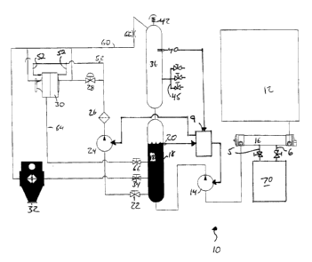
Reference will now be made to Figure 1 for a more detailed description of a
flameless
boiler unit 10. Flameless boiler unit 10 is preferably capable of producing
2.5 million
BTU/hr and captures this heat from one or more of three available sources:
engine
coolant; exhaust gases; and the use of excess engine horsepower to provide
shear heat
in the heat transfer fluid, which in this application will normally be water
boiled to produce
steam.
Heat from engine 70 is transferred to the engine's cooling system in which the
coolant
will be water, glycol or a mixture of the two. The heated coolant flows
through line 5 to
a heat exchanger 16, such as a shell and tube heat exchanger well known in the
art, and
returns to the engine via line 6. Both lines 5 and 6 can be valued to control
the flow of
coolant from the engine through exchanger 16.
Cold water for the present system is stored in a storage tank 12. A pump 14
pumps
water from storage tank 12 through engine coolant heat exchanger 16. Since the
heat
energy rejected to the engine cooling system cannot be used to generate steam
since
the temperatures of the coolant are normally too low for boiling water, heat
exchanger
16 is used primarily to preheat the water from tank 12 that is being pumped
into a
reservoir 18.
Pump 14 is a positive displacement pump and is used to add water to reservoir
18 when
the water level falls below a predetermined level. Signals from a level
indicator sensor
20 are used by a controller 9 to start and stop pump 14 when required.
-4-
CA 02474941 2004-08-06
Water from reservoir 18 is pumped from a location below the water line through
a valve
22 by centrifugal pump 24. The water is then pumped through a filter 26 and,
if valve
28 is open, into a shear heat generator 30. Generator 30 is typically a water
brake or
dynamometer mechanically coupled to engine 70.
Shear heat generator 30 results in heat being added to the water in two ways.
First,
while the tractor's engine is providing power to pump fluids and to operate
the usual
parasitic loads such as the alternator and coolant pumps, this consumes only a
fraction
of its available output, leaving excess capacity. Mechanically coupling the
tractor's
engine to generator 30 loads the engine and draws horsepower, which increases
the
amount of heat rejected to the engine coolant circulated through heat
exchanger 16.
Second, generator 30 itself converts the engine's mechanical energy into
thermal energy
in the water circulated through the generator sourced from reservoir 18. The
water brake
is set up to generate enough heat to boil the water and convert it into steam.
Approximately 2546 BTUIhr is generated in a preferred shear heat generator of
the
present invention for each horsepower of load on the engine.
The mechanical coupling between engine 70 and generator 30 is conventional and
numerous means of coupling them operationally together will occurto those
skilled in the
art. For example, as is known in the art, the truck's gearbox (not shown) will
have one
or more auxiliary power take-ofFs. One of these take-offs can be coupled to
generator
30 such as by means of a shaft, belt or chain. Or the engine's power take-off
can be
drivingly coupled to a gearbox vuhich in turn can be directly coupled to the
water brake.
As will be described below, one of the preferred aspects of the present
invention is that
adaptations to the generator allow it to run empty, which obviates the need
for a
gearbox, which saves considerable weight and expense.
Generally, generator 30 is a water brake which comprises a sealed chamber that
is
normally kept full of heat transfer fluid. A plurality of radially extending,
shaft mounted
blades, impellers or rotorlstators are disposed to rotate within the chamber
against the
-5-
CA 02474941 2004-08-06
shear resistance of the heat transfer fluid. The shaft is rotated by the
engine being
loaded through the mechanical coupling described above. The mechanical energy
from
the spinning rotors is converted to heat energy in the heat transfer fluid
which is
continuously circulated through the chamber to cool the water brake and its
seats and
to produce heated heat transfer fluid. In the present system, wherein the heat
transfer
fluid is water, the intent is to heat the water to the boiling point for the
creation of steam.
Pump 24 further allows water to be pumped through shear heat generator 30 into
exhaust heat exchanger 32. Heat exchanger 32 takes advantage of engine
inefficiencies. Specifically, most engine inefficiencies are from the loss to
the
atmosphere of escaping exhaust gases. In a typical 400 hp engine, the engine
may
reject up to 2.8 million BTUIhr from the exhaust system alone.
Heat exchanger 32 attempts to recover approximately two-thirds of the heat
loss in
escaping exhaust gases. This is accomplished by using an air to liquid heat
exchanger.
Due to the constraints of heat exchangers, however, the remaining one-third of
heat is
lost to the air. Obviously, improvements to exchanger design can be expected
to
recover a grater proportion of exhaust heat.
Steam and boiling water from exhaust heat exchanger 32 are then forced by
pressure
through a valve 34 into reservoir 18.
Reservoir 18 is connected to a steam tank 36 and gravity is used to separate
the steam
from the water. A pressure sensor 40 is used to sense the pressure of steam in
tank 36
and when this pressure falls below a predetermined value, controller 9 starts
or
accelerates centrifugal pump 24 to increase the flow of water to generator 30
to provide
additional steam to reservoir 18 and tank 36.
Tank 36 includes a safety valve 42 in case excessive pressure is achieved to
prevent
rupture.
-6-
CA 02474941 2004-08-06
Pump 24 is also used to provide water to cool seals and bearings in shear heat
generator 30. Reduced diameter (eg. one-quarter inch) supply lines 52 provide
water
from pump 24. These small lines fluidly connect with one-eighth inch orifices
inside
generator 30 as shown in Figure 6 that divert water against the generator's
seals and/or
bearings for times when the generator runs empty as will be described below in
greater
detail. Supply lines 52 bypass valve 28, and thus even if valve 28 is closed,
water is still
supplied to the generator for cooling purposes.
As indicated above, shear heat generator 30 can at times be allowed to run
empty. This
occurs when steam generation is not required. In conventional systems, a gear
box
would be required to disengage the generator from the engine. These gear boxes
are
however are heavy and expensive. To avoid this, the present shear heat
generator has
been adapted to run empty. Normally, this would cause the generator and its
seals to
burn out.
In the present system, the brakes' housing is 4140 HTSR (Heat Treated Stress
Relieved)
steel. Aluminum hardened to 85 rockwell is another alternative. Supply lines
52
continuously deliver a small amount of water to one-eighth inch orifices which
internally
direct water against the seals andlor bearings. When valve 28 is closed to
stop delivery
of water to shear heat generator 30, steam is allowed to flow through line 60,
through
restrictive orifice 62 and into shear heat generator 30 to allow any water
remaining in
generator 30 to drain into line 64, through valve 66 and into reservoir 18.
Without water in it, generator 30 simply spins without loading the engine. The
additional
hardening of the shear heat generator's housing and the continuous flow of
water
against the seals of the generator prevents erosion and pitting of the
generator's walls
and burnout, respectively. These adaptations to generator 30 provide
additional
advantages over conventional system water brakes which cannot be run empty.
_7_
CA 02474941 2004-08-06
The present system therefore derives heat from an engine coolant heat
exchanger, an
exhaust gas heat exchanger, and from one or more shear heat generators 30 to
heat the
water above boiling, which in turn provides steam to steam tank 36.
Tank 36 in a preferred embodiment will be connected to a manifold 45 on the
truck bed
or on the cargo box housing the boiler. This manifold will be used to fix
lines to run
steam to desired locations.
Another advantage of the present invention is that as pressure in tank 36 is
reduced due
to consumption, the boiling temperature of the water in reservoir 18
decreases, causing
the water in the reservoir to boil more aggressively to maintain a full head
of steam in
tank 36. This effect allows the system to kick in shear heat generator 30 and
exhaust
heat exchanger 32 to bring the pressure in the tanks back to a set pressure
which gives
the users of the present boiler unit steam on demand.
Reference is now made to Figures 2 to 4. All of the above described elements
can be
mounted on a truck for transport and mobility. A sample layout of the elements
is shown
in Figures 2 to 4. Water tank 12 is located behind a truck engine 70. The
location of
exhaust heat exchanger 16, steam tank 36, reservoir 18, shear heat generator
30, fuel
tank 72, gear box 74, control panel 9, and centrifugal pump 24 are shown in
these
figures.
Reference is now made to Figure 5 which is a flow diagram for a modified
flameless
boiler in which like numerals have been used to identify like elements.
As in the previous embodiment, heat from engine 70's cooling system is
captured by
heat exchanger 16 to pre-heat water from tank 12. Pump 14 draws water from the
tank
for circulation to exchanger 16, the water being discharged through line 17
where the
flow is split between line 19 which diverts some water directly to reservoir
18, and line
23 which directs the remaining flow to centrifugal pump 24.
_g_
CA 02474941 2004-08-06
From pump 24, the water is delivered through line 27 and the flow is again
split, with a
portion of the water being diverted into line 29 for flow through exhaust gas
heat
exchanger 32 and then into reservoir 18, and the remaining flow continuing
through line
27 to generator 30. As in the previous embodiment, reduced diameter lines 52
connect
with one-eighth inch orifices inside the generator that direct water against
the generator's
seals andlor bearings for times when the generator runs empty.
The main flow of water to generator 30 is controlled by an actuatable valve 31
connected
to a main settable pressure cutout sensor 33 mounted on reservoir 18 as will
be
described in more detail below. Obviously, when valve 31 is closed, all of the
flow from
pump 24 is directed to exhaust heat exchanger 32 with the exception of the
small
amounts that continue to flow into reduced diameter lines 52. This trickle can
drain back
into tank 12 through lines 59 or it can drain to atmosphere. Heated water and
steam
produced in generator 30 return to reservoir 18 either directly through line
37 and/or
through exhaust heat exchanger 32 by intersecting lines 29 and 37 (now shown).
As will be appreciated, this embodiment uses reservoir 18 for both heated
water and
steam collection.
The water level in reservoir 18 is maintained by lower and upper level
switches 57 and
58, respectively, connected hydrostatically to the reservoir. In the event
that the water
level falls below a predetermined lower level, switch 57 actuates an audible
andlor visual
alarm75. Switch 58 actuates pump 14 to keep the water level topped up to a
predetermined level. A one way check valve 15 prevents the reverse flow of
heated
water from reservoir 18 into tank 12. Steam pressure is monitored by settable
pressure
cutout 33. Steam pressure will normally be settable within a range from
approximately
10 psi to 150 psi and a normal operating range might be 80-90 psi. Cut out 33
actuates
generator on/off valve 31 to maintain steam pressure within the selected
range. As a
safety backup in the event that cutout 33 fails, backup pressure cutout 39 is
permanently
_g_
CA 02474941 2004-08-06
set at a maximum pressure and will shut off the flame to generator 30 off if
that pressure
is ever reached and can also be wired to activate alarm 75.
As yet another safety backup, reservoir 18 includes a safety relief valve and
over
pressure switch 42. The bottom of the tank is provided with a blow down valve
43 for
periodic draining to minimize the buildup of mineral deposits on the tank's
inner walls.
It will be appreciated however that unlike conventional boilers in which
kettle cake
undesirably insulates the water in the boiler from the heat source, the cake
will actually
insulate reservoir 18 against heat loss, which can be advantageous, provided
of course
that the build up does not significantly diminish the tank's capacity.
In this embodiment, there is also provided a steam return line 65 for those
applications
in which steam is used in a closed loop system and is therefore recoverable
either as
steam or as condensed water.
One skilled in the art will realize that the present system can also be
mounted in a
building or elsewhere and does not need to be mobile. In that case, the engine
could
be used for other purposes or it could be dedicated to flameless shear boiler
unit 10.
The boiler could be used in any application requiring steam.
The use of an internal combustion engine provides advantages over a flamed
boiler.
Regulatory bodies have set stringent controls for diesel engines for example.
This
includes lower allowable emissions set by the Environmental Protection Agency
in the
U.S.
There is also a fine line of control that is needed to balance the reduction
of nitrogen
oxides and particulate matter. Internal combustion engines are electronically
controlled
and can react fast enough to control emissions within each stroke of the
engine. This
is contrary to open flame systems in which no such controls exist.
-10-
CA 02474941 2004-08-06
The present invention can be r~;trofit using existing engines on rigs to
produce steam
required by the rig. Shear heat generators could be used to load the engines
to make
exhaust systems produce heat for steam production. When the engine is loaded
up with
normal rig operations, the shear heat generator can be unloaded to allow
maximum
power to be available to the rig.
The above described embodiments of the present invention are meant to be
illustrative
of preferred embodiments of the present invention and are not intended to
limit the
scope of the present invention. Various modifications, which would be readily
apparent
to one skilled in the art, are intended to be within the scope of the present
invention.
The only limitations to the scope of the present invention are set out in the
following
claims.
-11-