Note: Descriptions are shown in the official language in which they were submitted.
CA 02474983 2004-07-30
WO 2004/043809 PCT/US2003/029774
SHIRRED ELASTIC SHEET MATERIAL
CROSS-REFERENCE TO RELATED PATENT APPLICATIONS
[0001] This patent application claims the benefit of U.S.
Provisional Patent Application No. 60/351,936, filed January
25, 2002, and entitled "Shirred Elastic Sheet Material,"
which is incorporated in its entirety herein by this
reference.
FIELD OF THE INVENTION
[0002] The present invention is directed in general to a
shirred elastic sheet material and a method for producing the
same, and more particularly to a sheet material in the form
of a bag. The invention has particular utility in the high -
speed continuous production of elasticized plastic liner bag s
for trashcans, for example, wherein the elastic properties
enable the liner bag to be secured in place within a
trashcan.
BACKGROUND OF THE INVENTION
[0003] Plastic trash bags are produced and sold on an
extensive scale in a variety of shapes and sizes. The vast
majority of these bags are made of polyethylene film. The
bags in general include sidewalls that are often joined by
one or more seams, a closed lower bottom end, and an open
upper end. The trash bag can serve as a liner for a
trashcan. Conventionally, an upper edge of the bag, which
defines the open end, is rolled over an upper lip of the
trashcan to position the bag in an open position and to
secure the bag to the trashcan. It can be difficult to
maintain the bag in the open position and in a secured
CA 02474983 2004-07-30
WO 2004/043809 PCT/US2003/029774
-2
relationship with respect to the top of the trashcan when tlZe
bag is loaded with trash.
[0004] The use of elastic means for securing the open end o f
a liner bag to the top edge of a trashcan is generally known.
It is desirable for such an elastic top bag to provide
adequate "grip" to the can to prevent the bag from falling
into the can when loaded with trash. As a competing
consideration, however, because the cost of the elastic
component typically far outweighs the cost of the liner bag
material, it is also desirable to limit the amount of Blast z c
used to only that which is necessary to provide adequate
grip. Furthermore, since most trash bags are packaged in
rolls or in a highly folded condition, it is desirable that
the incorporation of elastic means on a liner bag does not
hinder conventional packaging techniques.
[0005] An attachment method used in the incontinence Indus try
involves the intermittent bonding or "stitch attachment" o f
heat-activated elastic film material onto a substrate such
that between every two bond regions there is a discernable
unattached length of the heat activated elastic film
material. The bonds are created by heat sealing or adhesive.
This type of basic pattern can be reproduced to make space d
intervals or "stitches" of attached and unattached section s .
Once the garment has been processed and activated (i.e.,
subjected to heat), the unattached portions of the elastic
material shrink to provide a shirred and elastic garment.
This attachment method can also be applied to making Blast i c
top trash bags, such as shown in U.S. Patent No. 5,120,138 to
Midgley and Tnternational PCT Patent Application No. WO
00/39005 to Marchal.
CA 02474983 2004-07-30
WO 2004/043809 PCT/US2003/029774
-3
[0006] Garment and diaper manufacturers typically apply pre -
cut strips of the heat-activated elastic film material onto
an article in a direction transverse to the direction of tha
article substrate in a production situation. This
intermittent stitch attachment method has been applied to
making elastic top trash bags. Such an attachment technique,
however, can be impractical in the case of plastic bags
produced by a conventional high-speed continuous bag machine
because it involves the intermittent bonding of individual
strip lengths of the elastic to discrete sections of a
continuously moving web, making consistent alignment of the
individual elastic strips with respect to the leading and
trailing edges of successive bag sections of the moving web
difficult to achieve. This problem is especially evident a s
the speed of the web varies during ramp up and ramp down
operations of the bag production machinery.
(0007] Accordingly, there is a need im the art for an
improved method of continuous production of elasticized liner
bags which is cost effective, enables high speed operation,
and is easily adaptable to existing bag machinery.
BRIEF SUMMARY OF THE INVENTION
[0008) The present invention is directed at solving some of
the problems with the prior art by providing a simple mean s
that will serve to keep a bag open in use, which is
advantageous in terms of cost, packaging and manufacture.
[0009] In one aspect of the invention, a bag is provided
which includes first and second side walls joined by first
and second seams, a closed bottom end, and an open top end.
A retaining element in the form of an elastic strip can be
CA 02474983 2004-07-30
WO 2004/043809 PCT/US2003/029774
-4
applied to one or both of the side walls adjacent the top
end.
(0010] A machine direction oriented film can be provided for
the retaining element which has a heat unstable condition in
which the material is "dead,"~ or set, and a heat stable
condition in which the material is "activated," or elastic.
The elastomeric film can be applied as a retaining element in
the form of a strip to a bag to produce an elastic top whic h
can help to maintain the bag around a trash can and help
prevent the bag from falling into the trash can. The
elastomeric film can be applied to the top of the bag by
being heat sealed or otherwise attached to the side wall of
the bag.
(0011] The heat shrinkable elastic material ~ can be applied to
a polyethylene web assembly in a high-speed production
situation. The elastic material can be attached onto the
polyethylene web in its heat unstable state. The material
can be activated to its heat stable state at a later point in
the process to yield an elastic top and shirred trash bag,
for example.
(0012] Advantageously, the elastic top bag can be easily
processed and activated. The elastic retaining strip can be
applied to a bag in a "dead" form and then "activated" aft a r
manufacture and packaging of the bag is complete. The
elastic retaining strip can be activated by directing heat to
the strip and/or generating heat on the heat-activated
elastomeric strip so that it may shrink. Attaching the
elastic strip in a deadened condition and subsequently
activating the retaining element to provide an elastic top
CA 02474983 2004-07-30
WO 2004/043809 PCT/US2003/029774
-5
can allow for the manufacture of elasticized articles in a
high speed, continuous, automated manner.
[0013) The invention can allow for the ready application of
elastic across the entire width of the bag. A portion of tYie
retaining element can be continuously attached across the
entire width of the bag. This method of attachment allows
for the unattached or,unbonded portion of the elastic strip
to shrink when the strip is activated. As the unattached
portion of the elastic strip shrinks, it displaces the body
of the bag, thereby causing the bunching or gathering of the
bag and producing an elastic bag.
(0014] Articles. formed by the method of the present
inventions can have at least portions thereof which are
shirred or gathered, as in the case of shirred openings in
food bags, dish covers, trash bags, and the like.
(0015] The invention can provide an efficient and economics 1
method of manufacturing an elastic top bag. The elastic
retaining element can be applied to a flap tie bag, a
gusseted bag, a flat top bag, or a draw tape bag which
includes a cinchable drawstring. The present method may al s o
be used in a variety of other fields and on other products.
[0016] As employed in the description and claims of the
present invention, the terminology "sheet material" and
"sheet sections" can comprise thermoplastic materials
suitable for the high-speed production of disposer and food
storage bags including, but not limited to, high density
polyethylene, low density polyethylene, linear low density
polyethylene and/or combinations thereof.
CA 02474983 2004-07-30
WO 2004/043809 PCT/US2003/029774
-6
[0017] Features of the present invention will become apparezzt
to one of ordinary skill in the art upon reading the details d
description, in conjunction with the accompanying drawings,
provided herein,
BRIEF DESCRIPTION OF THE DRAWINGS
[0018] FIG. 1 is a perspective view of a section of plastic
sheet material in the form of.a bag having a shrinkable,
heat-activated retaining element in the form of an elastic
strip mounted thereto in accordance with the present
invention.
(0019] FIG. 2 is a perspective view similar to FIG. 1,
illustrating the bag after the elastic strip has been
activated.
(0020] FIG. 3 is a perspective view of the bag mounted to a
trashcan with an elastic strip of the trash bag being used to
secure the bag to the trashcan.
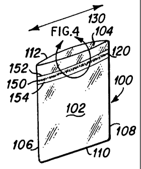
(0021) FIG. 4 is an enlarged, detail view of the elasticized
region encircled by arrows in FIG. 1.
[0022] FIG. 5 is an enlarged, detail view of the elasticized
region encircled by arrows in FIG. 2.
[0023] FIG. 6 is a cross-sectional view taken along line 6 -6
in FIG. 5.
(0024) FIG. 7 is a cross-sectional view taken along the l i ne
7-7 of FIG . 5 .
CA 02474983 2004-07-30
WO 2004/043809 PCT/US2003/029774
-7
(0025] FIG. 8 is an enlarged, exploded view of a heat-
activated elastic tape construction useful in connection with
embodiments of the present invention.
[0026) FIG. 9 is a perspective view illustrating the
fabrication of elastic top plastic bags from a continuous web
of plastic in accordance with the present invention.
[0027] FIG. 10 is a perspective view of another embodiment of
an elastic top bag construction in which an activatable
elastic retaining strip is attached to both ffirst and second
side walls of the bag.
[0028] FIG. 11 is a perspective view similar to FIG. l0,
illustrating the elastic material in an activated condition.
[0029] FIG. I2 is a top view of the elastic top bag of FIG.
1.
[0030] FIG. 13 is a top view of another embodiment of an
elastic top bag according to the present invention.
[0031] FIG. 14 is an elevational view of another embodiment
of an elastic top bag in accordance with the present
invention. having a tie flap portion.
[0032] FIG. 15 is a perspective view of another embodiment of
the present invention in the form of a gusseted bag having an
elastic retaining element attached thereto.
[0033] FIG. 16 is a perspective view of another embodiment of
the present invention in the form of a draw tape bag having
an elastic retaining element attached thereto.
CA 02474983 2004-07-30
WO 2004/043809 PCT/US2003/029774
_8
[0034) FIG. 17 is a cross-sectional view taken along the line
17-17 of FIG. 16.
(0035) FIG. 18 is a cross-sectional view taken along the line
18-18 of FIG. 17 with the elastic strip in a deadened
condition.
[0036) FIG. 19 is a cross-sectional view taken along the line
19-19 of FIG. 17 with the elastic strip in an activated
condition.
DETAILED DESCRIPTION OF EMBODIMENTS OF THE INVENTION
[0037,] Turning now to the drawings, there is shown in FIG. 1
an illustrative section of sheet material in the form of a
bag 100 which includes a first side wall 102 and a second
side wall 104. The first side wall 102 may be joined to the
second side wall 104 at a first seam 106 and a second seam
108. The first and second sidewalls 102, 104 define a close d
bottom end 110 and an open top end 112. The bottom 110 can
be joined by a heat seal or a fold in a U-folded ar J-folded
sheet material.
(003$) At approximately about one-half inch to about five
inches from the open top end 112 on the first side wall 102,
there is attached a retaining element in the form of a strip
120 of elastic material which may extend the entire width of
the bag 100 between the first and second seams 106, 108,
measured along an X-axis 130. In one embodiment, the elastic
strip 120 is a heat-unstable film which can be applied to the
first side wall 102 in a "dead" condition wherein the strip
is set. The strip 120 can then be activated by heating of ter
the manufacture and packaging of the bag is complete, for
CA 02474983 2004-07-30
WO 2004/043809 PCT/US2003/029774
-9
example, to an activated condition wherein the strip is
elasticized such that it is resiliently stretchable.
Providing the heat-unstable elastic strip 120 in a deadened
form can allow for the manufacture of elasticized articles i_n
a high speed, continuous, automated manner.
[0039] Referring to FIG. 2, the elastic strip 120 has been
activated by heating the bag 100. The elastic strip 120 has
been activated such that it is in an elastic condition. The
first side wall 102 can shrink in width in response to the
elastic strip being activated, thereby reducing the size of
the open end 112 of the bag 100 to provide a shirred
appearance to the bag.
(0040] Referring to FIG. 3, the bag 100 is shown secured to a
trashcan 140. The trash bag 100 is shown with the top end
112 wrapped around an upper lip 142 of the trashcan 140 with
the remainder of the bag 100 being inserted within a cavity
144 of the trashcan. With the elastic strip 120 activated t o
an elastic condition, the open top is elasticized such that
it can move from a constricted position, as shown in FIG. 2 ,
to a stretched position, as shown in FIG. 3, for securing t he
open end 112 of the bag 100 to the trashcan 140. The Blast ~,.c
strip 120 can stretch to allow the top end to move to the
stretched position and, in turn, provide a gripping force t o
retain the bag in place with respect to the trashcan 140.
[0041] Referring to FIGS. 4-6, the elastic strip 120 inclu.c3es
an attachment portion in the form of an attached region 150
which can be heat-sealed to the first side wall 102. The
attached region 150 may extend in a continuous seal across
the entire width of the bag 100 along the X-axis 130,
extending between the first and second seams 106, 108, as
CA 02474983 2004-07-30
WO 2004/043809 PCT/US2003/029774
-10
shown in FIG. 1. Referring to FIG. 7, the attached region
150 can be continuously secured to the first side wall 102 o f
the bag 100 by a heat sealing process, for example. There
are a number of different sealing methods which can be
utilized to mount the elastomeric retaining strip to the bag .
The elastic strip 120 can be secured to the first sidewall
using other techniques, as well.
[0042) Referring to FIGS. 4-6, the elastic strip 120 may
include first and second unattached regions 152, 154 with tlz-e
attached region 150 disposed between the first and second
unattached regions 152, 154. The unattached regions 152, 1 5 4
are integral with the attached region 150. The unattached
regions 152, 154 are not attached to the first side wall of
the bag, as shown in FIG. 6. The unattached regions 152, 1 5 4
may extend the full width of the bag 100 along the X-axis
130, extending between the first and second seams 106, 108,
as shown in FIG. 1.
[0043) Referring to FIG. 4, the regions 150, 152, 154 of the
elastic strip 120 are approximately the same height, measured
along a Y-axis 158, as each other. The Y-axis 158 is
perpendicular to the X-axis 130. For example, the elastic
strip 120 is approximately 3~ of an inch high with the
attached region 150 being approximately '~ of an inch high.
The remainder of the elastic strip is comprised of the
unattached regions 152, 154, each being approximately ~ of an
inch high. The first unattached region 152 is disposed
adjacent the top end 112 above the attached region 150. The
second unattached region 154 is disposed below the attache d
region 150.
CA 02474983 2004-07-30
WO 2004/043809 PCT/US2003/029774
-11
[0044] The attached region 150 can have a surface area which
is less than or equal to the combined surface areas of the
first and second unattached regions of the elastic strip 12 O
according to the following expression:
(AS ~ Au) ~ 1.
where AS is the surface area of the attached region 150 and A"
is the combined surface area of the first and second
unattached regions 152, 154. The relationship expressed
above can apply to an elastic strip with a height between
about one-half inch to about one inch, for example. In other
embodiments, with different tape materials, the relationship
between the surface area of the attached region and.the
surface area of the unattached portion of the retaining st rip
can be varied.
[0045] Referring to FIG. 8, the elastic retaining strip 12 0
can be made of three layers 170, 172, 174. The first layer
170 can be a soft sealable copolymer, with ethylene-vinyl
acetate copolymer (EVA) being preferred. The second layer
172 can be a rubber/elastomeric material, with ethylene
propylene dime monomer rubber (EPDM) being preferred. The
third layer 174 can be EVA. The EVA layers 170, 174 can be
used to facilitate attachment of the retaining strip 120 to
the side wall. The retaining strip 120 can comprise the
material marketed by Tredegar Film Products of Richmond,
Virginia under the name COX-702.
(0046] The three-layer construction can be oriented so as to
cause a set of the material that can later be activated by
the application of heat. The EPDM 172 layer is urged to
shrink along its length when heated to temperatures within
CA 02474983 2004-07-30
WO 2004/043809 PCT/US2003/029774
-12
its shrink curve of between about I00 to about 150°F, with
140°F being the preferred temperature, where maximum
shrinking takes place, ("the activation temperature"). Thus,
the EPDM layer 172 has at least two states. The first state
is the "deadened" or unactivated state wherein the EPDM layer
172 has a certain length. The EPDM layer 172 can remain in
the unactivated state until the EPDM layer 172 is heated
above the activation temperature. When the EPDM layer 172 is
heated above the activation temperature, the EPDM layer
achieves a second state, the activated state, wherein the
layer is urged to shrink along its length.
[0047] The manufacture of heat-unstable film for use as an
elastic strip is well known in the art as demonstrated by the
manufacturing methods and heat-unstable films disclosed in
U.S. Patent Nos. 4,820,590; 3,85,769; 5,182,069; and
4,714,735, which are incorporated herein in their entireties
by this reference.
[0048] Other suitable materials for the retaining tape can be
used in other embodiments. Additionally various blends and
grades of the general types of materials indicated above,
such as.EMA, EVA, Index, ULDPE below 0.900g/cc, etc, for
example, can be used with good results. In a further
embodiment, such blends as indicated above may optionally
include the addition of small quantities of a block copolymer
thermoplastic elastomer including, but not limited to,
styrene ethylene butadiene styrene copolymer (SEBS); SBS
copolymer, EPDM, and/or blends thereof, for improved
elasticity.
[0049] Polymeric receptive materials, such as EVOH, Carilon
polyketone (a product from Shell), and thermoplastic
CA 02474983 2004-07-30
WO 2004/043809 PCT/US2003/029774
-13
polyurethanes (TPUs), and/or ethylene carbon monoxide
copolymers such as Elvaloy (a trademark of The Dupont
Company) for example, can also be used to facilitate
activation by microwave heating as discussed subsequently
herein.
(OOSOj Referring to FIG. 9, an embodiment of a method of
manufacturing a bag including a retaining element according
to the present invention is shown. A bag assembly 200 can be
dispensed from a roll 210 of polyethylene plastic material,
for example. The roll 210 of polyethylene can be oriented in
the direction of extrusion indicated by the arrow 222. The
polyethylene plastic can be configured into a sheet which is
folded such that it has a generally U-shaped cross-section_
The folded sheet defines continuous first and second side
walls 102, 104 and the closed bottom end 110. The folded
sheet can be dispensed from the roll 210 to provide the bag
assembly 200. A roll 230 of retaining element ribbon can be
provided. Retaining element ribbon 232 can be dispensed from
the roll 230 and applied to the bag assembly 200. The
retaining element ribbon 232 can be continuously attached to
the bag assembly 200 with a continuous seal to provide the
attached region 150, and thereby define the first and second
unattached regions 152, 154. The retaining element ribbon
232 can be provided in a deadened condition such that the
ribbon is set and not elasticized.
(0051] when the retaining element ribbon 232 is attached to
the first side wall 102 by heat sealing, the heat sealing can
be performed at a rate such that the EPDM layer is not
allowed to shrink as it is being held under tension.
However, the heat-sealing.temperature can be sufficient to
bond one of the EvA layers to the side wall 102 as shown in
CA 02474983 2004-07-30
WO 2004/043809 PCT/US2003/029774
-14
FIG. 6. The heat-sealing temperature can be greater than t he
activation temperature.
j0052) Referring to FIG. 9, the bag assembly 200 can be cut
to define a bag. A sealing device has been used to make a
first cut to define a first seam 106 on a first bag 240 and a
second seam 108 on a second bag 241. The sealing device may
include a seal wire, a sever seal, or even a.bar. seal in
accordance with the known continuous production bag
manufacturing techniques. The bag assembly 200 with the
retainer element ribbon 232 applied thereto can be moved to
register the sealing device at a predetermined location from
the second seam 108 of the second bag 241 by moving with
respect to the sealing device in the assembly direction 222
substantially parallel to the X-axis 130 of the bag. The
sealing device has been used to make a second cut to form t he
first seam 106 of the second bag 241 thereby defining the
second bag. The first bag 240 has been made in a similar
fashion.
[0053) The first bag 240 is shown with the elastic ribbon 232
cut such that it defines a retaining element 120 which is
attached to the first side wall 102 along the entire width of
the bag 240. The retaining element 120 has been activated
such that it is elasticized to provide an elastic open top
end 112 for the first bag 240.
[0054) To activate the retaining strip 120, the bag 240 can
be placed in a 140° F or greater environment to provide
maximum elasticity and shrinkage. The temperature can be
varied with changes in the elastomeric film.
CA 02474983 2004-07-30
WO 2004/043809 PCT/US2003/029774
-15
(0055] Referring to FIGS. 2, 5 and 8, in the unattached are a s
152, 154 where the retaining element 120 is not attached to
the side wall 102, the EPDM layer 172 can shrink and cause
the EVA layers 170, 174 to shrink. Thus, the unattached
areas 152, 154 of the retaining element 120 can become
shorter. In the attached area 150 where the retaining tape
120 is attached to the side wall 102, the resistance provide d
by the side wall 102 prevents the EPDM layer 172 from
shrinking. Instead, the attached area 150 will pucker as
shown in FIGS. 5 and 7 to provide a shirred appearance.
Thus, the attached area 150 becomes shorter along the X axis
130 by.puckering (i.e. forming a serpentine path) as shown i.n
FIGS. 5 and 7. However, the attached area 150 is actually
the same length before and after activation of the elastic
retaining element 120.
(OOSG] Referring to FIG. 9, the activation of the second bag
can occur after the second bag has been packaged in a carton,
for example. After the plastic bags have been manufactured
and packaged, the package can be subjected to the activation
temperature in order to activate the EPDM layer 172 of each
bag loo.
(0057] Referring to FIGS. 10 and 11, another embodiment of an
elastic top bag 300 is shown. The bag 300 includes first and
second side walls 302, 304 which may be joined by first and
second seams 306, 308, a closed bottom end 310, and an open
top end 312 to thereby define a compartment 314. A pair of
activatable elastic strip retaining elements 320, 321 is
attached to the inside of the first and second sidewalls 3 O 2,
304, respectively, within the compartment 314. The retain i ng
strips 320, 321 can be similar to the retaining strip 120 of
the bag 100 shown in FIG. 1.
CA 02474983 2004-07-30
WO 2004/043809 PCT/US2003/029774
-16
[0058] Referring to FIG. 11, the retaining strips 320, 321
have been activated to provide an elastic top for the bag
300. '
[0059) Referring to FIG. 12, the top open end 112 of the bag
100 of FIG. 1 is shown. The first and second side walls 102,
104 are generally planar.
[0060] Referring to FIG. 13, another embodiment of a bag 400
having an elastic top is shown. The bag 400 includes first
and second side walls 402, 404 which may be joined together
at first and second seams 406, 408, a closed bottom end, and
an open top end 412. A retaining element 420 similar to the
retaining element 120 of the bag 100 of FIG. 1 is provided.
The first and second sidewalls 402, 404 of the bag 400 of
FIG. 13 are curved to present a generally convex outer
surface, thereby.defining a generally elliptical open top end
412.
[0061] Referring to FIG. 14, another embodiment of a bag 500
having an elastic top is shown. The bag 500 of FIG. 14 is a
tie flap bag. The bag 500 includes first and second side
walls 502, 504 joined at first and second seams 506, 508, a
closed bottom end 510, and an open top .end 512. Each side
wall 502, 504 includes a flap portion 515 extending from an
upper end 516 of the side wall 502, 504. The flap portion
515 can include a pair of ears 517 separated by a recess 518.
A retaining element 520 similar to the retaining element of
the bag 100 of FIG. 1 can be provided. The retaining element
520 can be attached to the first side wall 502..
[0062] The ears 517 of the flap portions 515 can be knotted
together to provide a closing mechanism to close the open top
CA 02474983 2004-07-30
WO 2004/043809 PCT/US2003/029774
-17
end 512. The tie flap ears 517 can be tied together after
the bag 500 is filled with refuse for convenient closing of
the top end 512 for disposal thereof.
(0063) Referring to FIG. 15, another embodiment of an elastic
top bag 600 is shown. The bag 600 of FIG. 15 is a gusseted
bag. The bag 600 includes first and second sidewalls 602,
604 which are joined together by a pair of gussets 607, 609_
The bag 600 includes a closed bottom end 610 and an open top
end 612. A retaining element 620 similar to the retaining
element 120 of FIG. 1 can be applied to the first side wall
602.
(0064) Referring to FIG. 16, another embodiment of an Blast: iC
top bag 700 is shown. The bag 700 of FIG. 16 is a draw tap o
bag. The bag 700 includes first and second sidewalls 702,
704 which may be joined together by a pair of seams 706, 70 8.
The bag 700 includes a closed bottom end 710 and an open top
end 712. A retaining element 720 similar to the retaining
element 120 of FIG. 1 may be attached to the inside of the
second side wall 704.
(0065) Referring to FIG. 17, the first side wall 702 can
include a hem flap 721. The hem flap 721 is attached to th a
first side wall 702 at a first hem seal 722. A first draw
tape 724 is located in a first hem 726 created by the first
side wall 702, the hem flap 721, and the first hem seal 722 .
[0066) The second side wall 704 can include a hem flap 731 _
The hem flap 731 is attached to the side wall 704 at a sec and
hem seal 733. A second draw tape 735 is located in a secorid
hem 737 created by the second side wall 704, the hem flap
731, and the second hem seal 733. The retaining element 7 2 0
CA 02474983 2004-07-30
WO 2004/043809 PCT/US2003/029774
-18
in the form of an elastic strip may be located below the
second hem seal 733 and may be disposed between the second
side wall 704 and the hem flap 731. The bag 100 also
includes a third hem seal 739.
(0067) The third hem seal 739 can be operable to define an
attached region 750 of the elastic strip 720 which .is heat
sealed to the second side wall 704, extending the full width
of the bag 700. The third hem seal 739 continuously attaches s
approximately one third of the retaining strip 720 to the
second side wall 704 and to the hem flap 731 ,
[0068] The remaining portions of the retaining tape 720 is
not attached to the side wall 704 or to the hem flap 731.
Specifically, a first unattached region 752 is located above
the attached region 750. In addition, a second unattached
region 754 is located below the attached region 750.
[0069) Referring to FIG. 16, each side wall 702, 704 can
include a notch 757 for allowing access to the draw tapes
724, 735, respectively. The draw tapes 724, 735 can be
operated to constrict the open top end 712 to provide a
closing mechanism therefor.
[0070]. In accordance with an alternate embodiment, the
retaining t.ape/elastic strip 720 can be attached to the bag
between the first side wall 702 and the hem flap 721 at the
first hem seal 722. This option reduces production costs b y
obviating the need for the additional length of hem flap
material as seen in hem flap portion 731 and the.third hem
seal 739.
CA 02474983 2004-07-30
WO 2004/043809 PCT/US2003/029774
-19
[0071] Referring to FIG. 18, the bag 700 is shown with the
retaining element 720 being in a deadened condition such tha t
the retaining element is set. The attached region 750 of t he
retaining element 720 is disposed between the second side
wall 704 and the hem flap 731. Referring to FIG. 19, the b~.g
700 is shown with the retaining element 720 being in an
activated condition such that it is elastic.
[0072) In other embodiments, the retaining element of the
present invention can be used in the production of a shower
cap type product which can be used as a convenient
elasticized article for covering food on a plate or in a
bowl.
[0073] The heat shrinkable elastic can be sealed to any
flexible film to create a shirred elastic band to secure the
film around a second object. This could be applied to
products such as diapers, hairnets, shower caps, bags, wrap s,
or a Quick Cover type product (Quick Cover is a trademark o f
S. C. Johnson & Sons). It may also be applied to the
packaging of products and industrial uses wherein
conventionally heated (such as hot air) shrink films are
employed.
[0074] Low crystallinity chain-entangled polyethylene
copolymers, for example, can be used to make the retaining
tape. These elastomers have chain-entanglements and/or
crystalline regions which behave as crosslinks. Suitable
materials include elastomers, such as EMA (ethylene methyl
acrylate), EVA (ethylene vinyl acetate), ESI (Dow Index
ethylene-styrene interpolymers), ionomers, and grades of
ULDPE (ultra low density polyethylene) below 0,90g/cc, mor a
preferably around 0.885g/cc, for example.
CA 02474983 2004-07-30
WO 2004/043809 PCT/US2003/029774
-20
[0075] The retaining tape can comprise an appropriate carbon
black campound with the selected elastomer to allow for
microwave activation of the retaining tape. Microwave
activation can greatly reduce energy costs and simplify
activation of the retaining tape.
[0076) A process for extruding and setting a suitable
elastomer for use in the retaining strip can include
extruding the elastic as a film by a blown film process or a
casting process, for example. The web of film can be cut
into a tape having a predetermined size, for example 1-1.25
inch wide. The tape can be stretched by being sent through
differential nip rollers, set at a ratio of approximately
5:1, for example, to stretch the elastic according to the
differential nip roller ratio, in the illustrative case five
times. In this manner the.polymer chains can be oriented and
stretched out, or set. The stretching process can be
conducted at room temperature.
[0077] After the elastic has been stretched, it experience s
some recovery. The elastic retains a portion of the maximum
stretched length, approximately about 50% to about 800, for
example, to provide the amount of set. The tape can then be
activated by subsequent activation techniques wherein a
substantial portion of the set can be recovered such that t he
elastic shrinks by about 40-50a. In the case of elastic
being stretched five times the original size, the retained
set can be approximately 2.5 to 4 times the original length.
j0078] Methods for activating the elastomeric film of the
retaining element include conduction heating in a batch or
continuous oven, convection heating by convective airflow,
microwave activation, infra red (IR) activation, and
CA 02474983 2004-07-30
WO 2004/043809 PCT/US2003/029774
-21
activation by solvent application, for example. Methods of
heat transfer include conduction, convection, and radiation.
Conduction usually involves the transfer of energy through a
solid. Convection usually involves the use of a gas or
liquid (in general a fluid) and is also influenced by the
laws of fluid mechanics. Lastly, radiation involves heat
transfer through electromagnetic waves or photons.
[0079] As, discussed previously, heating the retaining elemerit
is one suitable activation method. The application of heat
to the elastic can cause the polymer chains to coil which
results in the macroscopic shrinkage of the elastic tape.
Heat can be applied to the elastic to cause shrinkage in a
multitude of ways including use of conduction heating in a
continuous oven or a batch oven for cartons/cases and
convection (forced air) heating of the bags, for example.
[0080.] A continuous oven usually includes an inlet, an
outlet, and a heating zone disposed therebetween. A conveyor
system can be provided for transporting items into the inle t,
through the heating zone, and out the outlet. The oven can
include other zones which cool the item, draw out gas and
smoke, etc. The continuous oven method offers an advantage
from a processing aspect in that, with efficient heat
distribution, there is the ability to manufacture bags unde r
substantially uniform thermal conditions.
[0081] Using a continuous oven, a steady state process can be
provided wherein inactivated bags can be inserted into the
oven where they can be activated. A plurality of bags
disposed in a carton can be placed in a continuous oven at a
predetermined temperature, such as, between about 150° F and
CA 02474983 2004-07-30
WO 2004/043809 PCT/US2003/029774
-22
about 190° F. for example, for a predetermined residence time ,
such as about 3.6 hours per carton at a temperature of about
190° F, for example. The parameters such as the time and
temperature can vary.
[00$2] Convection heating can employ heated forced air to
warm the retaining element. Unlike a continuous oven or a
batch aven, warm air is,blown directly onto the retaining
element through slots or nozzles. Convection heating offers
a short travel path for the heated air or gas which leads to
higher heat transfer rates and hence faster processing rate s .
Convective heating can be combined with conventional ovens,
microwave ovens, and/or infrared (IR) systems with the
movement of~air facilitating the distribution of heat.
[0083] For convection heating, high velocity heated air can
be blown directly over individual bags or stacks of bags.
The heat used to warm the air can be generated by a number o f
different sources such as heating coils, gas, exhausted hot
air drawn from a piece of machinery, etc. The heat can be
directed at the~top of the bag where the heat activated
elastomeric film is situated.
(0084] In one embodiment, a plurality of bags each with an
unactivated elastic retaining element can be disposed in a
carton. The bottom flap of the carton can remain unsealed t o
allow for the blowing of high velocity hot air into the
carton.
(0085] In another method a stack of bags can be pinched such
that all but a top portion of the bag, the upper 2 inches,
for example, are retained. Jets of hot air coming from
different directions can be directed at the top portions of=
CA 02474983 2004-07-30
WO 2004/043809 PCT/US2003/029774
-23
the bags. To provide a more uniform activation of the
respective elastic tapes, the stack of bags can be suspended
by the closed bottom ends such that the open upper portion o f
the bags is disposed below the closed ends.
[0086] In other embodiments, the bags can be disposed in
different orientations for convection heating to improve the
uniformity of the heating, In other embodiments, the
velocity profile of the heated airjgas can vary.
[0087] Another method of activation useful in connection w i th
the present invention is with the use of an IR system. IR
heating is based on absorption of waves in the infrared
range. The IR method uses electromagnetic,waves for heating
an object.
[0088] An IR source can be finely adjusted to emit radiation
in a specific wavelength range where one material will abso rb
the energy but another material will not. In a situation
where two different materials exist, it can be possible to
selectively heat one material while not heating another by
tuning a radiation source to give off a majority of its
wavelengths in a specified range. The emitter can be tune d.
to give off radiation in the range where the material desi red
to be heated can absorb a maximum amount of energy while t he
other material absorbs a minimal amount of, or no, energy.
[0089] This phenomenon is especially advantageous when one
wants to heat one material while keeping the other materia 1
cool. The IR method can provide a very intense and short
blast of heat, which is also useful when one wants to even 1 y
warm one surface while keeping other materials and surface s
CA 02474983 2004-07-30
WO 2004/043809 PCT/US2003/029774
-24
unheated. The IR heating can be combined with convection
heating, for example.
(0090] With this activation method, infrared radiation can be
used to heat up the elastomeric material while not heating
the remainder of the bag. Such heating is possible because
the elastomeric material can absorb radiation in wavelength
ranges which are different from the wavelength ranges of the
other materials) of the bag, for example polyethylene. A
source can be selected to emit radiation in a specified range
of wavelengths where the elastomeric material can absorb the
radiation and the polyethylene will not.
[0091] A microwave oven can be used to drastically improve
processing time and cost of operation. An industrial
microwave oven typically includes three main components: an
oven cavity where .objects can be bombarded with microwaves, a
magnetron which produces the-microwaves, and a wave guide
which transfers microwaves to the oven cavity. A continuous
microwave oven typically includes a vestibule which sari ac t
to trap all non-absorbed microwave energy so that radiation
is prevented from escaping into the surroundings.
(0092] By making the retaining tape receptive to microwave s,
the tape alone can be heated while avoiding heating the
relatively..larger mass of plastic material comprising the
remainder of the bag, typically polyethylene. Microwave
activation allows for relatively shorter residence times
during processing than either conduction or convection
heating and allows for varying production volume with only
slight processing modifications.
CA 02474983 2004-07-30
WO 2004/043809 PCT/US2003/029774
-25
[0093] Microwaves induce heat by being absorbed by the
substrate and causing molecules to vibrate. The positive and
negative elements in the molecules align themselves
respectfully to the negative and positive field of the wave_
Since the wave is constantly varying between the positive and
negative field the particles move back and forth rubbing int o
each other. The friction from the vibrations in turn cause s
heat.
[0094] Electromagnetic radiation in the form of microwaves
can be used to heat the elastic where microwave receptors a re
added to the elastic material. Microwaves can heat materia 1 s
through the dielectric properties of the material.
Dispersing a conducting phase into a non-conducting phase c an
cause other heating phenomena, called interfacial or Maxwel 1-
wagner heating, which can be caused by the build up of
charges at the interfacial regions of the conducting and nori-
conducting phases. Alternatively, since the field is
electromagnetic in nature, materials that exhibit magnetic
permittivity losses can be heated, as well.
[0095] There are materials well known in the art that may be
added to an elastomer to allow for microwave heating.
Conductive carbon black is one such material. Conductive
carbon black masterbatches are available commercially from
many compounders, such as Ampacet, A. Schulman, and Modern
Dispersions Inc, among others. The carbon black
masterbatches can have high loadings of carbon particles,
around about 30o to about 45% by weight, for example.
[0096] A retaining element having a construction wherein t he
carbon black masterbatch is included at 1000 concentration as
a thin core layer of a three layer coextruded film can be
CA 02474983 2004-07-30
WO 2004/043809 PCT/US2003/029774
-26
provided. The two outer skin layers can contain the
elastomeric material detailed previously. The layer ratio o f
this construction can be the first outer elastomer layer
being about 45%, the second outer elastomer layer being about
45's, and the core carbon black layer being about 100. In
other embodiments, the core layer can have a different ratio ,
either higher or lower. Such a tape can be elastomeric, heat
sealable to the bag, and microwave heatable for activation.
The sealability of the elastomer provides a mechanism by
which it can be attached to other articles. In other
embodiments, the retaining element can have other
constructions with the number of layers being different.
[0097]. In one embodiment, the carbon black retaining elemeri t
can be attached to a bag by being sealed thereto to define an
attached region and at least one unattached region. The
retaining element can extend along the entire width of the
bag, extending from the first seam to the second seam of the
bag. Each bag can be about 24 inches wide, for example. The
carbon black retaining element can be attached to the bag ire
an unactivated condition. A plurality of such bags can be
made and grouped into one or more sets of bags. Each set o f
bags can be placed in a carton for storage thereof.
[0098) The cartons can be placed in any FCC compliant
multimode continuous microwave, for example. A combination
of a power setting of about 20kW to about 30 kW and a
residence time of about 60 seconds to about 90 seconds can be
used for activating the retaining element to cause the bags
to shrink from their original width of 24 inches to an
averaged width of about 16 inches. Operating the microwave
at a power setting of about 22kW to about 25kW can help to
eliminate excessive melting of the carbon black elastic
CA 02474983 2004-07-30
WO 2004/043809 PCT/US2003/029774
-27
construction. Carbon black can have an exponential heating
curve such that, it tends to heat more readily under microwave
energy as the temperature of the carbon black is increased.
[0099] Another material that can be included in the retaini ng
element for activation by microwave heating is an iron oxide
such as the ferrite magnetite, Fe304, for example.
[00100) Ferrites are iron oxides that may contain other mete 1
oxides and have ferromagnetic properties, for example
magnetite (Fe304) is a ferrite. Ferrites can interact with
the magnetic component of microwave energy. The magnetic
properties of ferrites arise from the dipole moments of the
unpaired spins of the 3d electrons in metals such as iron.,
manganese, nickel,, cobalt, etc. These magnetic dipoles
arrange themselves in magnetic domains made of many atoms
with their dipoles aligned in the same direction. Thus each
domain has an overall direction or orientation. In a given
small amount of material there can be many domains each
pointing in different directions. Where this random domain
orientation exists, such as with the ferrite material, for
example, the domains tend to cancel each other with no
macroscopic magnetic behavior being observed. However, wha n
a magnetic field is applied, the domains that are more or
less aligned with the magnetic field can tend to grow at t he
expense of unfavorably aligned domains thus increasing the
overall material's alignment with the magnetic field. Thi s
change results in domain wall movement which requires energy,
dissipated as heat. When microwave energy (which is a
rapidly oscillating electromagnetic wave) is incident upon a
ferrite, the domains can tend to grow and shrink with each
oscillation so as to align with the field. This rapid domain
CA 02474983 2004-07-30
WO 2004/043809 PCT/US2003/029774
-28
movement results in energy dissipation, magnetic lossy
behavior, and heat generation.
[00101] At elevated temperatures the domain structure tends to
break down due to the thermal agitation of each dipole. Thus
the material transitions at higher temperatures from an
ordered domain structure to a randomly oriented collection of
magnetic dipoles. The transition is from ferromagnetic
behavior to paramagnetic behavior. After such a transition,
the domain structure no longer exists and the individual
magnetic dipoles can become very compliant to magnetic fields
such that the ferrite no longer exhibits lossy behavior in
the microwave field and it consequently stops heating. The
temperature at which this transition occurs is called the
"Curie temperature." The transition can be gradual or quite
abrupt over a large or short range of temperatures. Thus the
Curie temperature can be a temperature range over which the
ferromagnetic properties decline.
[00102] The Curie temperature can be controlled by the
composition of the ferrite, such as by blending the iron
oxide with other metal oxides such as-nickel, manganese,
zinc, etc. in a predetermined amount, for example.
(00103] In addition.to this ability to "shut off," ferrites
can have a logarithmic heating curve with increases in
temperature (i.e., the ferrites' heating rate decreases as
the temperature increases), as opposed to an exponential
growth, thereby facilitating heating control and allowing for
greater tolerances and operating ranges in a continuous
production setting.
CA 02474983 2004-07-30
WO 2004/043809 PCT/US2003/029774
-29
[00104] Suitable ferrite powdered materials are available from
Ceramic Powders Inc. of Joliet, Illinois.
[00105] The ferrite material can preferably have a Curie
temperature between about 100°C and about 110°C. This
temperature is sufficiently low to prevent melting of the
polyethylene~bag film, but high enough to cause shrinkage of
the elastic.
(00106] The Fe304 iron oxide can be blended into a polymer
resin t o create a masterbatch that can in turn be blended
with the elastomeric materials to render them heatable. The
iron oxide can be compounded with an elastomeric resin at
about 25o by weight loading to allow for microwave heating of
the material. The iron oxide Fe3O4 can exhibit magnetic los s
characterized by its magnetic permittivity which can be
analogous to dielectric loss.
(OOiO'7] Bentonite clays may also be compounded with a polymer
as a masterbatch. Bentonite is also known as montmorillonite
and can have a chemical formula
NazO ~ 2Mg0 ~ SA~zOy 2 4 Si02 ~ ( 6+n ) Hz0 . Bentonite can contain
varying amounts of alkali metal oxides such as Na20 and K20
and alkaline earth oxides such as Ca0 and MgO. The bentonite
crystal structure contains typically 5% bound water by weight
but may also absorb additional water. This water can be
heatable by microwave energy.
(00108] A bentonite masterbatch can be blended into a polymer
at a predetermined percentage, between about 30% and about
40% bentonite material by weight, for example, to render the
material microwave heatable yet not hinder elasticity or
sealability. The carrier resin of the masterbatch can be an
CA 02474983 2004-07-30
WO 2004/043809 PCT/US2003/029774
-30
elastomeric material so as to limit the impact on elastic
properties.
[00109] Yet a further material which can be blended with an
elastomeric material to allow microwave heating is an ECO
(ethylene carbon monoxide copolymer), such as is commercial) y
available from Dow as Covelle films or from DuPont as Elvaloy
resins, for example. The oxygen molecule bound to the carbon
in the polymer backbone can create a dipole moment which is
heatable by microwave energy. Such an ECO is disclosed in
U.S. Patent No. 4,600,614, which is incorporated herein in
its entirety by this reference. The ECO can be blended with
an elastomeric material to provide microwave heatability t~o
the construction without adversely affecting elasticity or
sealability. The ECO-elastomer material can have a single
layer or multi-layer construction.
[00110) In other embodiments, the microwave can have a numbs r
of different modes. The microwave can be cycled. The bags
can be placed directly in the wave guide to subject the
retaining elements to a tremendously intense microwave fief d.
[00111] Alternatively, a solvent can be applied to the elastic
retaining strip to cause chain coiling for activating the
strip. The solvent can have predetermined solubility
parameter such that when the solvent is delivered to the
retaining element, the elastic can shrink. Suitable solven t s
for activating the shape recoverable elastomers described
above include but are not limited to hexane, heptane, xylen e,
toluene, chloroform, etc. These solvents have a solubility
parameter such that they do not dissolve the shape
recoverable polymer.
CA 02474983 2004-07-30
WO 2004/043809 PCT/US2003/029774
-31
[00112] In other embodiments, a combination of convection,
conduction andJor radiation systems can be provided.
[00113] All references, including publications, patent
applications, and patents, cited herein are hereby
incorporated by reference to the same extent as if each
reference were individually and specifically indicated to b ~
incorporated by reference and were set forth in its entiret y
herein.
[00114] The use of the terms "a" and "an" and "the" and
similar referents in the context of describing the invention
(especially in the context of the following claims) are to be
construed to cover both the singular and the plural, unles s
otherwise indicated herein or clearly contradicted by
context. Recitation of ranges of values herein are merely
intended to serve as a shorthand method of referring
individually to each separate value falling within the range,
unless otherwise indicated herein, and each separate value is
incorporated into the specification as if it were
individually recited herein. All methods described herein
can be performed in any suitable order unless otherwise
indicated herein or otherwise clearly contradicted by
context. The use of any and all examples, or exemplary
language (e. g., "such as") provided herein, is intended
merely to better illuminate the invention and does not pos a a
limitation on the scope of the invention unless otherwise
claimed. No language in the specification should be
construed as indicating any non-claimed element as essenti a 1
to the practice of the invention.
[00115] Preferred embodiments of this invention are described
herein, including the best mode known to the inventors for
CA 02474983 2004-07-30
WO 2004/043809 PCT/US2003/029774
-32
carrying out the invention. Of course, variations of those
preferred embodiments would become apparent to those of
ordinary skill in the art upon reading the foregoing
description. The inventors expect skilled artisans to employ
such variations as appropriate, and the.inventors intend for
the invention to be practiced otherwise than as specificall y
described herein. Accordingly, this invention includes all
modifications and equivalents of the subject matter recited
in the claims appended hereto as permitted by applicable law.
Moreover, any combination of the above-described elements i n
all possible variations thereof is encompassed by the
invention unless otherwise indicated herein or otherwise
clearly contradicted by context.