Note: Descriptions are shown in the official language in which they were submitted.
CA 02475008 2004-08-06
WO 03/065939 PCT/AU03/00122
'I~(JI~I'J'LAR FRO.STI~SIS AS~sE~t.Y IN~.~.TJDINCr TAl?EJ~F.~ AL)~'U~~TTS
t~.AC.CrR(~U~Il~
The pt'esent invention relates to improvat.~ents in surgical prostheses and
more
paxkicularly relates to a prosthesis assembly including tz'.~utua,Ily
intexacting tapexed
S adaptat' elements capable of use ~ knee and other skelefial prostheses and
~nrhioh allow
during implantstidn, fyne adjustabiiity o.f at least one caznponent of tlae
prosthesis
assembly through at least eve degrees of freedom namely; zotation about ~, "f'
and
Z axes, vertical adjustmEnt aio~.g the Z axis. Although the assembly will
primt~xily be
descxibed with rei"exence to its application in adjustment of lettee
prostheses ~.t~d
paxticularly ~ti~bi~.1 and femoral com.~ponents, it will be appreciated by
persons sl~led in
the art that the double tapex a~-rax~gements tQ be described may be applied in
otl~ex
prostheses ~.t skeletal sites such as but not litr~xted to shoulders, hips,
ankles, ~n~exs
at~d in dental appizcations.
PI~..T~711~ Al~T
1.5 ~.ee arthroplasty is a well-known. suxgical procedure by which a diseased
andlox
dammed n~.t~,tal knee joint is repla.Ced by a prosthetle knee joint. Typical,
l~r~ee
prostheses incit~de a tibial component, a .femoral component, at~.d a Qatellar
caxnponent. Ivtodern total knee replacement involves the resurfaci;~.~ of the
femoral
condyles with a. metallic component, roughly approximating tl~e shape of the
2Q anatomical fe~nc~ral condyles, and resutv.cin~ the tibial plateau rwlth
usually, but n.at
exclusively, a polyethylene component hawing a metallic tibial base plate,
Optimal
oo.~foz'ity between the polyethylene of the tibial e~r~pcyz~ent and the
meta,l,lie i:'e~tc~~'al
component has .izt the past been a p~rok~len~ area. Tdeally t~.e femoral
component should
be oan~r'ae:ot with the top of the tibial cc~.mponent in order to mir~ittti~ae
wear tsf a
~5 surface liner which is usually polyethylene. The di. ..f~"'.~.c~lty,
however, is that tlxe knee
jofnt does net act as a fixed axis hinge. During normal xrzovements ofi the
ktyee,
rotation of the femr~t' upon the tibia occurs, and roll back of the fez~uaral
candyles upon
the tibia occurs, particularly when the knee is flexed. The pzo~ision of a
bearing in the
form of a cataa mechanism between the femox~.l component and the polyethylene
tibial
30 component :means that vvlth increased ~lexaon of the knee increased
posterior
ixanslation. ~rf the femoral, component upon the tibia ocouxs, the bearin.,g
between the
ti~xal and t'emoral component. is incongruent, and therefore tbeareti.cally
undesirable,
CA 02475008 2004-08-06
WO 03/065939 PCT/AU03/00122
resulting i~n high contact stress, leads to increased wear of the surface
line' which is
usually plastics. I~or example, if the plane of the tibial. plate when fitted.
to the tibia is
misaligned with the resected proximal sa,~rface of the tibia, uneven, wvear
will result
between the articular surfaces. A patient m.ay not notice tlxe misaligr~rtaent
and unetren
S loading at:' the femoral, component o:n. the tibial eotrxpc~ztent but
wvl~exe the laad:c~,g is
cax~cetltratcd tht'ough one ca:atiyle wear is accelerated- Tlt~s znay .lead.
to a reduct~az~
of up to 50 °/a of the norm~,i. life of the prosthesis
The fezr~.axal campaner~i generally includes a ,pair of spaced apart ca~dylar
portions, the st~pexit~r surfaces of which articulate with a portion of the
polyethylene
tibzal oompane~~ A femoral steox assembly, used to prov~~.e lateral
stahi.li.ty tt~ the
replaced lrnee joint, sEats wxtlxiti the mednllaxy cavity of a distal portion
of a. femur,
~.~td is typicahy fixed to the femoral component by specialized ~ixstion, such
as a.
collar and ba.l.t_ Soz~c~e prosthetic knee faints include a taper which
:r..o~.y be a Morse
taper, that cxtes~ds from the baclr surface of the femoral component to mate
with a
1.5 femoral sleeve that is securable to the femoral steztx assembly.
A femoral sleeve, which helps to till spaces at the opea.ir~g of the medullary
canal, coo.
also provide fot' a modular assembly alJ.owitxg a surgeon to select tlxe mast
appropriate
femoral stem. from a selection of stetxxs having dilferet~t le:ogths and
diameters for
attachment to one of a selection of ~'etztoxal components. This tatodulaz-
oonfiguratiao
significantly reduces the number of i~divid,ual cornponet~ts that zoust be
purchased,
stacked, and used. during a surgical procedure. Although the fer.~toxa.l stem,
whatever
its dixoehsions, is usually angled with respect to the inferior surface of the
femoral
component and either of'~ set az~terioriallylpo$terially or ~ a central
location, it is
sameki.~r.~es desirable to ariet~t the femoral stem perpendicularly with
respect to th.e
back surface. For example, depending on particular patient requiremetxts, the
femoral
stem may need to be offset fore or aft with respect to the front of the
femoral
compat~eot. similarly, the femoral stem may need to be angled varying degrees
to the
left ar xiglat with .respect to the frost plane of the femoral component. .A.
Morse type
taper post, is izztegrally cast as part of the fexnaral
compat~.ent.1~'urthermat~e, there is a
requirement for a range of sizes oftlae overall femoral component- Therefore,
in order
to accommodate all of tlxe possible corxtbinations of ovetaIl femoral
component site,
fc~re/neutral/aft positianin~ of the Morse type taper poet, and
lEi~lperpendicularl~ight
2
CA 02475008 2004-08-06
WO 03/065939 PCT/AU03/00122
angling of the Morse type taper post, a doctor or haspits.l is required to
maintain sn
undesirably substantial stock of lance prosthesis components. )despite the
existence off'
knee joint prosth..eses having modular components, there remains ~. need fc~.r
s. :modular
levee joint prosthesis assembly that has gxeater versatiXity of adjustment to
sccommodate differing patient anatomy attd a rnisal.igned components.
An example af. ~ known knee prosthesis a~~xaz~gement is disclosed in US
1?'stent
~,a~~,449 to Ro~ertsoti Jr. Tbst patent discloses a dual taper stetxt
extension fa:~ lee
prosthesis for surgical implantatiazt to a patient's leg bone at the knee
joint area. Tlte
prosthesis includes ~. prothesis body portion. that extends transversely
relative to tkte
patient's intramedtxllat'y canal far caxxyin~ a beaxin,g suxface that
~,~~.cttlates with the
patient's adjacent l.eg bone or virith another pros'tl~.eszs component. A
conical corinectox
e~,tends from tY~e prosthesis pnrtiatx end along an. ~c~is that generally
frocks the
patient's intrametlullsry canal. A, ste:tn nxenyber includes ~'n'st and second
end portions
ar~~. has a central l.oztgitudinal stem axis. The stem membex includes a
soclzet at each
end porCior~ for forming cat~nectxons to the conical connector at the
respective end
portions as selected by the surgeon. (~tte of the socl~ets leas a Central
lon~itud~t~.l axis
that genErally coincides with the ceritrsl. longitudinal axis of the stem. The
otf~et'
socket has a centra,1 longitudinal axis that fot'trrs an acute angle wvilh the
axis of the
stem. The arxa,ngetnent disclosed in tlxis ,patent allows the surgeon to
select from a
clxoice of two 1:ape~r angles the valgu"s angle lox' ~. stem extension that
wlh best ~t the
patients intramedullary canal but once the a;~gle is selected the cotypl.~g
allows only
two degrees r~f~reedoa~r~ i.e. axial and rotations.l nxovetnent.
A,notlxet' lclaown knee prosthesis is disclosed in U~ patent 5.?8~,~~1 to
~al~exan which
teaches a modular knee prc~stl~es~s including a Morse t~.pe~' post that is
rnatahl.e yvith a
first portion, of s femoral sleeve, A,. second portion. of the femoral sleeve
is joined with
a femoral stem that is intraducilaJ.e within the meduilaxy canal of a distal
poz~ion of a
femur. The modular l~zyee .prosthesis includes a femoral catnponent, a bolt,
and a
Morse tape~t post. The femoral oornpo:ne~nt leas s. superior surface, sn
inferior suxface,
and an. aperture. The bolt includes a ~hesd portion engag~.ble with the
superior surface
~b of the fiemoral component to inhibit movement of the bolt through the
femoral
ca~npQner.~.t, and an elo~xgate shaft portion that extends ~rom the head
portion of tlye
halt. The elongt~te shaft paxtion has a length sufficient to protrude through
the
3
CA 02475008 2004-08-06
WO 03/065939 PCT/AU03/00122
aperture beyond the i.tt~exior surface of the femoral component. The Morse
taper post
is enga.gable with the elang~,te shaft portion of the bale to .reta.in the
Morse taper past
in, a fzxed positi.o:n. with respect to the femay'~.1 component attd the
distal. end of the
lV.Iorse tapEr past is intraducibl.e within a femora.I. sleeve. .
S United Mates patent 5,800,552 teaches ~. Mechanicalty linked hinged total
lcitee
prastltesis. A resurfacing type of total knee prosthesis is disclosed wltiah
also
provides a pasteri.or. stabilization .function t~vet~ the entire range of
flexi.an.. ,T. he knee
prosthesis provides primary at' supple~nez~.t~xy posterior stabilization of
the
reconstructed lttaee joint by .rne~ns of a unique mechanical ca.tnlfoIlawer
mechanism,
which is integrated within the tt~edi~l and Iatera.l distal condy~e~ of the
fem.axal
component to pxovide functiat~~I compensation for lost, resected or
incampetez~t
posterior cruciate ~i.g~.ments or to work iri conjunction with surgi.cal.ly
xet~.ined vialSIe
or questionably t~~bie cruciate lig~~ent structures of the reconst~racked knee
joint,
The invention extends to prostheses including a hinge connection t~~.t defines
a
1.5 posterior stabilization eat~str'uctiort separate ,front that defined by
the condyles. One
ettnbadiment off' the invention extends individually to the posterior
sta~6i~i~zin~ hinge
assembly.
A,.nather knee prastbesis disclosed iri. US patent to McMintr. camlarises a
femoxa.I
camponenty a t~'bia.l component ~,nd a rtteniscal component tfterebetween, a
stabilising
~0 peg extending i;'roatt the tibial compattent tlat'ough an elongated slat in
the rne.c~,~
catxtponent and into axt opening in the ~emaxal. component between. a. pair of
condylar
members thereof The part of the peg extending through the slat allov~ts the
meniscal
component to rotate and also to move linearly about the peg along arse path,
whilst tf~.e
part of the peg izt said open.i.ng engages cam surfaces on s, praject~ozt
between said
25 condylar tttetttbers as the knee is flexed, itt vse, ~,nd said Ii~.eax
movement of the
ttte~ziscal component occurs.
'fypicaliy a. knee prosthesis will comprise a femoral caznpanent for secztring
to 'the
femur, an opening devned by the fe~rtaral component, s, tibial component Fox
securement to the t~-bia, an opening through the tibial component, a bearing
3~ ccrnpanent between the f~maxa.I and tibial components, the femoral
component and
the bearing cotxtponent ha.t~itxg respective cmvcd articulatory beaxing
surfaces of
Congruent .form, ate elongated slot in the bearing component, a Ioca,toz'
se~srate fxo~m
4
CA 02475008 2004-08-06
WO 03/065939 PCT/AU03/00122
the tibial compon~~tt, a stem part of the locator e~tetlding from att enlarged
part
thereat'; the stem part extending through the opening in the tibxal component,
thuraugh
the elongated slat in the bearing eompc~nez~t, and into the opening defined by
the
femoral cot~xpanent, the bearing cameon.ent being capable of rotational
movement
about tlae locaxor, and the elongated slot ~ the bearing component h~.~ring a
width,
such. as tar .prevent relative lateral movetrtent between the .locator and the
bearing
component, and a length to allow linear mQVeznez~t of the bearing component
relative
to the locator along one path. Tlae linear moveme:~t occurs, in use, upon
flexion of the
knee, anal the enlarged part of the locator being disposed at an appr~site
side o~f the
l.(~ tibial. cottaponent to that at which the bearir~.g caaraponent engages,
and being ave~rsi~ed
relative to said apeni.ng through the tibial campoxtent so as to prevent
passage of said
enlarged part tt~exethraugh. Bx'anaples of resurfaci.;a,g types of total knee
prosthetic
devices are also disclosed .'tn the following US~ patents incorporated by
reference
herein. U.~.Pat.TTt~.3,774,~44 tc~ Walker; US patent 1'~d.3,7~8,742 to AvexiXl
et ai. U'.~.
1.5 Pat No.4,081.,86G and U.S. P'at, Via. ~4,2t~7,627 to Clorxtxer.
Although the issue of and need for greater versatility of adjustment of
prostheses has
been addressed in a. number of prior ark anratlgements such as those described
above,
there i.s sti.~l. a need to increase the adjustability oi" a;rt~ciai faints
relative to
20 orthogonal ~~' and ~ axes azxd 1'dtationally thr4ugh zz~'ultiple three
dim~ensfat~a.I
degrees a'1~~t'eedarn to mare easily cc~aztpensate for unwanted
rrtisalignments.
n~rv~.rr~rzorz
There is a lorxg felt want in the art to provide a convenient zzteans for fine
adjusttnetlts
of prostheses tavhere an initial ~t i~ not in conformity with. alignment
parameters. 11'ar
25 example, in the case of a tibial coropanent of a .knee prosthesis the
tibial plate gay
xtat align with a patient reference pa~.t~e. The rnisaligmm.ettt ~x~ay be in
one o~' rndre
planes ax in one or mare axes. According to present arrangetrnen~ once the
tibial
component has been inserted as best the surgeon can, unwanted misalignments
are
tolerated due to tyre si;~ni~caut p~-ablems in resetting. Accurate ~~ation ref
the tibial
30 component to ensure proper a.lignTnent is a ~iif~cult surgical objective
particulsr-ly due
to tl~e difficulty in. accuratel~r preparing the medull.ary cavity in the
tibia. In other
bane sites and joinfs of the skeletal. frame it would be an adva~t~.ge if a
surgea~n could
~nal~e fine axigl, rotational, Iatcral and auteriorl posterior adjustme;~ts
through :multiple
s
CA 02475008 2004-08-06
WO 03/065939 PCT/AU03/00122
planes snd axes as this would allow correction of any misaligrazxtents ar non
conformity with iaserExon parameters.
The present invention provides an assembly including an cdaptor which allows a
surgeon to ~oc~ake one adjustments to a. co~mpanEn~t wl~zclt directly or
it~diu~ectly
anchored iu bone_ Tb.e assembly is capable of use with a variety of batxe and
skeletal
joint prast'hesi.s, Far instance the assembly and associated adaptats :tray be
applied ~
effecting fine adjustments to dental fixations, tibial and femora~I
i;t~2plants ( dis'~I oar
prax.irrral), anklesy fingers and a variety of other joints and bone saes,
Tt is tlaerefc~re an object af. the invention to provide a madnlar prosthesis
assezxtbly
1Ø including an ~daptar which. allows increased versst~lxty of adjustment to
accommodate
predetermined insertion par~.~eters, patient anato~any, joint attitude and
conditions
while maintaining a relatively law component cauzzt. It is another object of
the
invention. to provide a modular prosthesis assembly'includin~ carr~pa~tents
that are
physiologically and geometrically canxpatible with di~e~ent anatorrucal
conditions,
Still anot'~ex object of the i.nvet~.tit~zt is to provide a modular prosthesis
that is suitable
for use in bone sites and _jaints such as but not limited to slaaulders and
ar~lcles~ t'i.g:~t
and left knees. l.t is a further abject of tk~e invention to provide an
adaptar far use with
a bane prosthesis and which alla'~vs adjustment of a component attached
thereto
through at least five degrees of freedmn namely ratati.on about X Y and Z
orthagancl
axes, axial extexssirr~a along the Z axis and displacement relstive to and Y
axes,
ttte~-eby enabling a surtgeon to make ~n.e realignment adjustments to the
carnpanent to
mo~'e accurately mate. the component with patient geometry .
A,lthaugh the i.»vention will be pritnsrxly described ~ritl~. :reference to
its
application to fee prostheses it will be recognised by persons skilled in the
art that
tl~e adaptor and associated taper art'angements described herein whiak~ allow
five
de~xees of freedom far fne adjustrJaerlts to the attitude of a component nay
be
applied in other prostheses such as tz~.ay be used to repsir fingers,
t'~tu~nbs, shoulders
and ankles. ',Fhe assembly znay also be wed in dental appli~cstions where a
component
is used to anchor an. axtji~ZCia1 tooth, to a jaw bone. Zt will be appreciated
by persons
sleilled in the art that tapers other than a IVIorse type taper may be used an
the
assembly and adaptors aceorcling to the invet~tiar~.
6
CA 02475008 2004-08-06
WO 03/065939 PCT/AU03/00122
Typieallyy a ~t~wn modular 1~».ee prosthesis includes a femoral cr~mpazt~nt, a
bale, ~~d a Morse iype taper past. The fczx~a~r~.l component bas a. franc
sur:F~.cc, ~. back
5t~.rface, and an spezture extendin.,g t~.ere betwcen_ The bolt includes a
head portion
engagable with thwfxo:at surface of the :l'e:moral campo~.ezzt to inhibit
movement of the
bolt tlutough the ~et~.trx~.l component, atzd are elongate slxa~t portion that
extends from
the head pozfiian of the bolt. The known. tibial component of a knee
prosthesis
comprises a tibial plate which receives a polyethylene lit~.ex which provx~les
an
articular surface ca aperatiaag wit the femoral cotopanent. Lntegxal with the
Tibi.al
plate i.s a stem adapted fox insertion in a medullary cavity of txbx~.l bane.
The stem is
frictio~~ fitted and may be cemented .into a s~~itably resmed trae~.rxllarry
cavity. Hr~we~rer
if the re~t>L~etl cavity is i»aeeuxately farmed, the tibxal plate ~ ar
carrespa:ading fEmaral.
camponet~t) may sit at an angle relative to a bane section cut by the surgeon
as a
refere:~ce prior to insertion ref the tibial component. Untie the knowxz tt-
bial component
is inserted, the preferred way a correcting alig~ax~e~t adjustment may be made
is to
remove the tibial compoxzent and. try to re set it. This is an undesirable
solution to
misalignta'tent as a refit will possibly result in a pata;trti,al,ly weaker
bane l cotrapottent
band..
According to one embadirnent of the invention, there is provided a. modular
prosthesis
assembly t'ox use in but n.at limited to such joints as knees and shoulders
wherein the
assembly includes an anchoring member insertable in bone, at least one adaptar
and a
component set according to a pt~edetet~rxzined reference and which simulates
an~.tomical geametcy; wherein the adaptor engages the anchoring member arld
the
companeni to al.l.ow adjustment of said co~tnpt~nent in the evet~.t the
component is
misaligzred with a predeterzrrined anatomical. reference.
According to another embodiment, the prosthesis assembly comprises ~.n
anchoring
raetnber insertab~e in a bane cavity, a tibial campor~e~t which is capable e~
mating
with. the anchorio.g zx~ember; an, adaptor capable of co operating with s~.xd
anchoring
membex and the tibial component to allow fzne adjnstmet~t of the tibial.
component.
Accardit~g to a preferred embodiments the tine adju~.sttr~ents of the tibial
component
zxa~.y be axial, rotational about ~,'~ and ~ axes or offset .relative to a
l.an.gitudinal
a.~,zs.
CA 02475008 2004-08-06
WO 03/065939 PCT/AU03/00122
In one broad :~c~~rm the present invention. comprises:
a prosthesis assembly far implantation. irr a sl~eletal site; the a~sscx~.t~Iy
comprising;
a l:wrst compt~nerit for fxaaion in a bone c~.viiy, a second component capable
of direct
ar i:~di~ect engagement with the first eamponerxt;
at Xeast one adaptr~r ~r>~ich engages said first ~,nd second components
~khexek~y all~owi~g
adj~rstxne~t ref the second catz~p~:~ent from a first dispasi~it~n of the
second cornporaent
relative to a predaternained reference.
~referabVy, the first component provides an anchorage irr said bane for the
assembly
and receives the at least titre adspte~t; wherein the at least tree adaptor
joins the first
1a component to the second component.
P.re~erably, the,jainin.,g s.daptox includes a body having an external tapered
region and
a tapered inter' recess, whcrEin the extems.l tapered region releasably
engages the
fast component and the inner tapered recess receives therein the second
eornpcrraent.
Th.e seGOnd coznpcrnent is preferably adjustable tlrraugh at least four
degrees of
15 freedQt~ relative to said rcference~ namely Ister'~Ily, angularly~ axially
or rotatiorxally
relative to ~, 'Y' end Z axes. The external tapered. region is preferably
sym:rtretx~G
relatt~re to a l~rtr,gitudinal axis afraid adapter.
.A,ccording to one embodxtr~.ent, tl~e izkner taper of the adaptor is err
axial with the
external taper. .r4.ccordirxg to another embodiment, a loragitudnnai axis of
the inner
~0 taper is disposed at an angle tc~ a longitudinal axis of said. ad~.ptt~r.
The inner taper. znay be offset relative to but parallel to a
lottgi.t~xdi~na.I axis of said
aclaptar or the inner taper znay be offset from a.~n.~. at an angle relative
to a Iangitudinal
axis of the adaptar. Ti he first carnpc~nettt, includes a tapered recess which
engages
said external taper ol:' said adaptor and the sect~nd component pre~'ex~ably
comprises a
2S tibial piste connected to a. tapered stem. In another' embodiment the
.ftrst component is
a femoral implant.
Its another broad farm, the presetxt invention cc~tz~.prises;
s
CA 02475008 2004-08-06
WO 03/065939 PCT/AU03/00122
a rnoduiax prosthesis assembly comprisinga an. ~.zxchorage component
inserta~bl~ in
bony anal a coupling compa~.~z~t which cQ apexates with said anch~rxa.g~
component to
asso:rne a first predetcx~.z~ine~ orientation. relative to said an~hox~ge
component; the
assembly further eompxxsix~~ an adapter inscr~.ble between said anck~.oz'age
componexxt
and said Go~upling camps»ect to allow a scct~t~d~ry adjustment of said
coupling
component relative to said ~xst predeterr:m~ncd orientation of said coupling
campanent.
Preferably, the anchara~e member and the coupling member are capable of
engagement with each other r~i.a gale /female ar femaie/ male tapers,
fre'i~ex~tY~ly, the
IQ adaptor is enga,gable with the anchorage miember and the ca~.pling member
via male/
female or fen~aiel male tapers.
:in another broad fox:tn the present invention comprises:
An adaptor Pot' use with a ,prosthesis asse~~?aly for implantation in, a
skeletal site, th.e
adaptor including a body having an external t~.pered region and an inner
tapered
1.5 recess, and whexezn. said external tapexer~ xegit~n engages a
carrespan.~li~tg tapered
recess of a first implantable compancnt ol:'said assembly and the inner
tapered recess
receives thexeixx a second component of said assert~bly.
The adaptor which is preferably cyiit~drical, aliaws adju~strnerit of said
second
coxxlponent relative to a first engaged position of said second component. In
vne
~0 eix~bud~inaent, the inner taper is cc~ axial with the cuter taper. In
another embodiments
the inner taper is disposed at a.n. angle to a longitudinal axis of said.
adapter. The inner
taper may be r~ffset from but parallel to a langitudi.:oal a~cis of said
adaptor.
Alternatively, the inner taper is c~t'f,'sct .from and at an angi.e relative
to a longitudinal
axis of the adaptax.
2~ tn another form the present invention ca~mpxises:
a lszaee prasthests comprising a .fe~.aral campanent for attachment to a
femur, an
opet~:ing defined by the femoral ac~~ponent, a tibias ca~ponent far attachment
to a
tibia, ari opening through the tibias component, a bearir~,g component between
the
femoral and ta.'bial campanen, tiae femoral component and the 'bearing
coit~,ponent
9
CA 02475008 2004-08-06
WO 03/065939 PCT/AU03/00122
having xespectivc currratl. articulatary bearxn.,g suxfaces; the knee
pxosthesis furthex
comprising; an adaptor ~~pabla of use with s~.id tibial or femoral component;
wherein
s~.xd adaptor enables secondary ar~hagas~~,l., rotational lateral ar~.d ~,~aal
a~ijustm~n~k of
said tibial and femoral components.
In another broad. form the present invention comprises:
a prosthesis ~.ssambly far implas~t~tion in a skeletal situ; the assembly
compxising;
a first anchorage component faz fixation in a 'bane ~~.vity, a second
campa~ant
capable of direct of indirect engagement with the first camponettt;
wherein, tho anchorage component comprises a tapered recess which receives a
i 0 cor.'responding tapexed zt~~mber of said second component; wherein sazcl
tapered recess
has a longitudinal axis which. is laterally offset from and !or disposed at an
angle to a
longitudinal axis of said, anchorage campartent thereby allowing
adjustzn.~.t~t of the
second component from a. first disposition of the secr~nd component r~elati~ve
to a
predetermined reference
Tn a further bt'aad form the present invention. ca:tnpxises:
a rrxodular prosthesis for ixnplatttataon in a joint of a skaletai :Frame,
wherein the
pxasthesis includes a proxxt~nal component having a part for ~~cat7ian to bane
and a
formation for receiving a joi.rting member, ~,nd a distal companet~t; wherein,
the
joinit~,g zx~.eznber enga~,,gcs a dis~l mezxxber; said distal mcm:ber
ix~cludang a recess
which rccei.'~es therewithin at least one insextable clement, whexein s~.id at
least one
element includes means to receive and a~' retain said joining membex; wherein
said at
least a:ae element enable axthogor~al, rotational ~.~td axial adjustment a;f
said joining
member.
Its az~othGr broad farm according to a zr~ethod aspect the present inventia»,
comprises:
a method rrf insertion of, a modular prosthesis assembly in a hone site of a
sl~eletal
frame, wherein the modular prosthesis assembly ootxxprises; an anclxorage
campoz~ent
to
CA 02475008 2004-08-06
WO 03/065939 PCT/AU03/00122
inserk~6Xc inn bone anal a coupling cenaponent which ce o~cx~.te~ with said
a.txcherage
campenettt tc assume a ~t predetermined orientation reI$tive to said ancboxage
carr~panet~t; the assembly ~~urther comprising an adapter insextable betwec~
said
anchorage ceix~.pvnent and said ct~upling camponei~t to allow a secendary
adjustment
of said ca~.plir~g component xelative to said ~~xst predetermined
c~rientatian; the
traetlxod comprising the steps of
a) tal~ir~g a;a anchorage cenxponent and insexting said compa~;ent itt bon.E;
b) taking a coupling corr~panent and placing said coupling component in
erxgagement witi~ said anchorage eetrtponent so that the coupling compo:~e~t
assumes
a first orientation;
c) checking the 1-lxst arientatian ef t~xe ct~upling compr~zte~nt tt~
determine xf tlxat
arienta~.~ion is a desired oxzex~tation relative to s. pxedetermined
anatettxical reference;
d) in the event that the first arientatien is incot'rect relative to said
anatomical
refer~~ce, removing said ceupling member 1''rotya etzgagement with said
anchorage
r~ex~aber;
e) eztga,ging said aclaptc~~r with said anchora~.ge member and en.~aging said
cauplin,g :ct~e;mber with said adapto~';
f) adjusting said adapter and ler said coupling metr~ber so that said
oouplit~g
member assuar~es a secondary dispesxtic~~ which is a prel"erred e~ientatic~n
relative to a
predetermined anatotttical reference.
Prel:'er~.bly the adapters i:nclu~le a taper, such as but not limited to a.
Morse which
engages components having a. corresponding tapex.
~5
11
CA 02475008 2004-08-06
WO 03/065939 PCT/AU03/00122
BRI>;F' 1~ESCT~Ip~fJI~T ~1~' THE DRAWI~1'~S
'fife present
invetrtion
will be
now descz~bed
according
tt~ a.
preferred
but non
lzrszitzng
embc~di.ment
snd with
refexence
to the
accotnp~aying
illustrations
vvhexein
lw figure shows an. 'underside perspective view of a typical
1 tibial cam~onent.
Figure shows a tQp side view of the ti'bi.ai cortxponent
2 of Ii.gure :l.
Figure shows a frQt~t elev~,tian view c:~t~he tibi~i
3 component of ~~ure 1.
Figure shows a side elev~.txon view Qf the tibial component
4 o:f ~~ure 1.
1~'i~ure shows a lc~n.g sectional elevation o ~. down tibial
5 component inserted
in a. tibial stem
1.0 Figure 5 shows a long sectional elevation of a lrr~own tii~i~l componeztt
irtsetted
izt a tibial stem having ~.z~ angular o~'set.
Figure ? shows an exploded schematic view ~i:'~. series of prosthesis
~ss~alies
in ~.ccQrdance witlx the pxesent inv~ntion_
Figure $ shc~vvs a perspective view of ~.n artchora,~e member
3.5 Figure 9 sbr~ws a top view of the ~.,~chora~;e member of tire $
Figure '.t~ shows a long sectiat~~.~ view of the anchorage member of figure 8
taicett at line l~-D of Iigt~re I 1..
Figm~ I. I. shows an elcvati,~n view c~f the anchorage member of f gore 8
Figu;e 12 shaves ~. perspective view of an anohot~.ge rnerr~ber with offset
angular
20 recess.
>'i.guxe 1~ shows a top view of the anchorage t'raember of
figure 1~
Figure 1.4 shows a long sectional v~e~ of the ~nchora~e membet'
c~f i2gure 1~
taken at line EmE bf figure 15.
Figure 15 shows an el.ev$ti~ari view of the anchorage nnerx~ber
of figure 1 ~.
25 Figure I~ shows a perspective view of ~ neutral revision
anct~ot'~,ge member'
( ttbi~.l stem) .
Fi.gu~'~ 1? shows a top view of the anchorage member' of figure
l6
Figure IS shows an. elevation view a the anchorage member
offigure lb
Figure 19 shows a long sectional el,ev~.tiazt view of the
~.ohorage membet~ of
30 ~gurc 18 taketl. ~t G-Cr,
Figure ZO shows a perspective view of a .revision anchorage
member
( tibial stem) with lateral offset.
Figttxe 21 slxows a top view of the arac:hor~,ge member of
figure 20
12
CA 02475008 2004-08-06
WO 03/065939 PCT/AU03/00122
Figure ~2 shows an elei=icon view of the ~,~clnor~.ge member of figure 20
FigurE 23 shows a long se~tio~al elevation view c~f the anchorage t~o.~~nber
of
~guxe ~0 taken at F-F,
Fi.,gure ~4 shows ~. top view of an a~laptor according to one ~x~abodimcnt
witlx ~.
laterally offset inte~-n~.l tspered cavity.
Figure 25 slows a long sectional view t~f the adaptor Qf ;~gur~ Z4 takers at
~in~
A-A.
k'igttt'e 26 show's ~ tap view of an adaptor according to o~n~ ~t~bodiment
with ~.
laterally offset internal tapered cavity.
Figure 27 shows a long sectional view of tlye adaptox of figure 24 trak~~ at
line fi-
Fi.guxe ~8 shows a tap view of an adaptc~x ~.r~oxding to one embadirrietlt
with a
laterally offset internal tapered eavaity.
Figure 29 shows a leng sectional view of the adaptor, of figure ~4 taken at
line C-
C.
Figure 3Q shows an elewstiozt view of a rcviSiott $sse~bly including a late.~-
~1
adjustment seeor'ding to one em~bodime~.t c~.~the invention.
Figure 31. shows a long section of the assembly of figure ~() ta.ken ~.t line
I -~ I.
Figure 32 shows an el.evatzo~ view of a revi.s~o~ assembly with vertie~.i
~0 adjustment according to ozle embodiment of the i.~~rez~binz~.
Figure 3~ sllt~ws ~, top view of. the ~sseznbly of f gore 32.
Fitxuxe 34 aborws a long section. of tlxe assembly of figure 32 tae at line ~T-
~.
'The invention will be pz'itnarily descri'l~ed vrrith reference to its
application in knee
2S prostheses. It will lae appreciated however, th~.t tl~e assembly described
herein
including the use t~f an angolsr a.~d/t~r lateral offset for re adjustment of
a component
rnsy be applied in a variety of skelefial sites itxeluding but not li:tnited
to shoul.d~',
ankle, finger, thu~t~.tb joints. Also the assembly a~sy be empl.oyetl in
dental.
appli.cati.ons. In kno~vtt total knee Irrt~stlaeses the articular surface of'
the distal I'emt~t~
30 and proxit~a~.l tibia are 'usually but not exclusively replaced with
respeo~ve metal and.
plastic contlylar-type axtxcular bearittg components. The knee prostheses
prow~itie
adecxuate rotatioz~ai and tra:~slstional freedt~xn and requi.~;e minimal
l~o:~.e resection tc~
accommodate the compo~.ents withuct the bounda~'xes of the available joint
space. 'tee
patella..femoral joint zxaay also be resurfaced by a third ~rzosthetic
cozzlponent, as well.
13
CA 02475008 2004-08-06
WO 03/065939 PCT/AU03/00122
The fes~noral, tibial and patella prosthetic resurfacing ctr~xrpt~~.o:nts
a.~ra af~~te~. to
respective, surgically prepared adjacent bone structure by caxno~ti.~tg ar by
bia~agacal
bone ingr0wth. The femoral Component is us'aaby but nc~t exclusively a
metallic allay
coz~structxt~n such as orrbalt ohxome ~llc~y arid provides medial and lateral
candylar
bearing surfaces of similar shape and geometry as the nat<uo~l~ distal
fan~u,~'. 'fhe tx'bial
co:rnp~nent aax~ be made entirely of ultra higlx ~o~aau~lax ~vai,ght
pal~~bylor~e ar can
be cornprisyd. of, a metall.ia base at~d. stem. aonapat~~nt dista..lay and are
interl.ao.~xn.g
plastic (LTHIVIVVI'>) component, proximally. The plastic tibial plateau
bearing
surfaces are of concave multi-radius geometry to mare ar less match the
a~icu~~,r
geonzetxy of the mating femoral condyles, depending upon the desired desi.,gn
nxeohanics of primary femoro-tibial oration, E.g. the ~lexia~n-exta~si.oz~,
~nol~ding
poster~ox rollbaok and rotational and i~anslational articular orations.
The fe.~tnoral and tibial components are positioned on the respective side of
thy knyy
1.5 joint and are not orecbanicaUy canoected or linked together ( unlike the
case of
consfrained or hinged type of knee pxostheses).
Additionally, i.~t rysurfa.cing types of fatal kt~.oo prostheses the tibial
plataau~ bearing
surface geometry can assume a variety ol" cani'i,gurations, depending upon the
desired
e~ctont of articular cootaot az~d associated translatiol (medial-lateral anal
at~to~iar-
pastanit~r) and ratatiana~ (axial and varus-valgus) secondary femorQ-tibial
:~xtc~i~ons.
'these various seoondary tt~atiaos allow the resurfaced lc't~ao to function in
a :~atu~'al-
like 'biomeohanical manrryr in conjunction with the surrounding ligatt~entous
and
muscle structural about the knee joint. The viable salt tissue structures
Fu~totiox~lly
2f maintain the femoral and tibial bearing surfaces in con..ta.ot, provide the
necessary
levcl;~ of constraining ~'ot'co to achieve k;~oe joint sinbility, at~~3
decelerate the principal
motion in. flexion-extension and secattdary motions, stroll as axial rotation,
etc, in a
Got~trollEd rrrartner. Additiat~a.lly, this functional intcractia~t bet4veen
the s~,ort~unding
tissue structures aid the implanted kiaee prastriysis minimizes abrupt motion
stoppagE
3a ofi impact ~oadin~ of properly designed prosthytic a.rtieular s~.i-F',acos,
and this prevents
overstryssing at the coznpanEnt ~tion interface.
The objective in knee ~repla~.ceznents is to ;ai~ulate vuitl~. a dynamic
impia~xt,
natural knew functiat~ as closely as possibly a.~,d. any i~mpr~vem~nt v~rh~ich
allaWS a.
surgeon greater flexibility in. achieving this objective is dcsir~,ba,o. The
attioulatioz~ of
14
CA 02475008 2004-08-06
WO 03/065939 PCT/AU03/00122
the femoxa~I eondyles r%~~ith the tibial plateau 'bearing surfaces is complex.
bioznechan.ics allowing pritx~~.xy femoro-tibial. flexion and extension, and
secondary
m.oti.~rz~s of axial ~.z~d varus-valgus rotations and anterior-posterior and
medial.-lateral
translations, all afwhieh occur itt the normal kt~~e joint. ~'ha knee joint
reaction farces
du~~i~.g primary o:r secondary matic~n are pri~.~ips.lly supporked by the
tll~xal 'bearing
surfaces, and to sot~e extent by 'the Camlfollawex surfaces, and are
transferred to the
underlying fixatiota interfaces at~d adjacent suppoztive bane structures. 1n ~
.t~c~~al
knee, pbysioiogical fet~ortr-tibial ra~~bacl~ starts at the onset of knee
flexion and i.s
generally mostly completed by ~0 degx'ees of flexion.. This rollback is
accompanied. by
x0 a transitional motion. of rolling and sliding. In the normal hneea tlxese
comple~c
interactions arE acoaznpartied by ~o~plex active interaction of the anterior
and
posterior o~xtciate ligaxr~ents and othEr sz~rro'~oding adjacen:k soft tissue
structures.
Tile above is a description of known l~i~ot~~~hsnics afa knee joint
prosthesis.
~'he present i~v~ntion d~s~~'ib~d herein with refetencE to alt~~ative
embodit~~:~ts,
1~ provides ~. prosthesis asse~xlbly includi~xg adaptt~rs which eoabl~ a.
surgeon. to m~a~o
fine adjustments to tl'~~ disposition or attitude of a cc~rr~.po~x~nt to
enable that
component to he disposed such that it will allow more accurate simulation of
anatomical geometry or dyn~,mio action at an i~nplat~t site in a patient.
Figure 1 shows an underside perspective view of ~. typical tibial compo~ex~t
1. Tibial
20 eomponen~t 1 comprises a tx~bial plate 2 and a tibial. stern 3. An
underside sux'faoe of
plate 2 :rosy be adapted witlx a porous coating 4 ~t~t or without the use ot'
a bone
growth pramt~te~' klydroxyapatite. Alternatively, as shown with reference to
surface 5
the underside surface of plate 2 may be roughened by grit blasting. Figure 2
slao~vs a
top side view of the tibial component I off' ~.gu~re :~. 1~'late 2 includes ~.
fornnation
25 which z'eceives and retains a polyethylene layer which provides a bearing
surface frat'
an opposing fe~naral cQmp~oz~ent, Figure 3 shows ~, front eleva~tion~ view of
the tibial
oompQnent 1 t~f fgure 1. Figure ~ shor~rs a side elevation view of the tibial
ooznponent of figure 1.
Figure 5 shows a lotlg sectional elevation of a known tibias campot~.e~t '~
inserted co
30 axially in. a tibial anchorage member 8 inserted itz zxaedullary cavity 9
of tibia 1Ø
item 11 t~.f plate I4 engages recess 12 such that a longitudinal axis of stem.
l :l is o0
axial with a longitudinal axis of recess 12. 'Tibia includes a resected
plateau 13 twh~ich
provides a reference for tibial plate l~ upon inset~tion~ in medullary cavity
9. As shown
in figure 5 tibial plate 14 may be out of alignment with a,~ anatamic~,l
reference such
is
CA 02475008 2004-08-06
WO 03/065939 PCT/AU03/00122
as plateau. 13. 1n that case, where the surgeon anticipates the possibility of
an out of
alignment of. piste 14, an anclxorage with an; angular affect :arasy be used
to adjust the
attitude of plato 14. l~cferrin~g to figure 6 thexe is shown a long sectional
elo~abit~r~ of
tibial component 7 insErtcd its. a ti$ial stEm hav~itxg an angular of~'sct.
Tibial cor~pt~nent
~ 7 is inserted co sxis.lly zn a t~bial anchorage morrlber 15 insortod in
medul.lary cavity ~J
of tibia 10. Morn 11 of Plato 14 engages recess 16 such that a longitudins.l
axis of
stem 11 i.s offset relative to a lt~z~gitudinal antis of recess I6. Tibia IO
irrclndes a
resccted. plateau I3 r~rhich pravi.des a xoference for tibial plate 14 ttpo~n
insertion. ira
medullary cavity 9. As shown ~.tt ~tgure 6 tibial. plate 14 is novv .in
alignment with
platoau. 1~ so tho optimal pasitio~ of tibiai. piste 14 which is co planar
with its
referotzce plateau :l3 will facilitate annotate simulation of joint
georxtetry.
Thus, according to coo embodiment of the invention, a suxgeon is able to
effect an
adj~usttx~ont to a cr~~npo~aent by means of az~ offset in provi.dotl with or
in an ~.t~.ohorage
set in a br~x~e site
1~
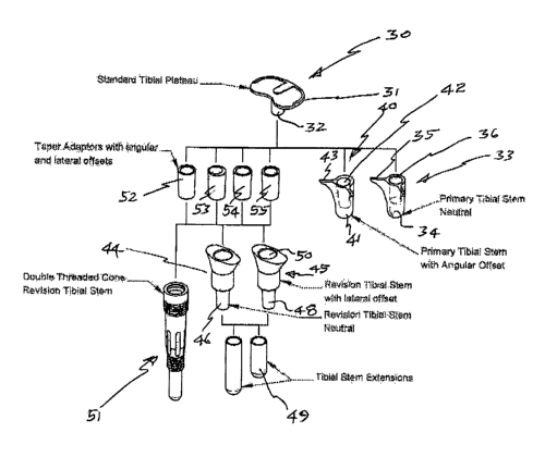
Re:~e~'xzt~g to figure 7 there is shown, a schematic exploded Iayout of
vari.o't~
ootn~ponents capable of use in the pxosthersis asscmlaly aoooxding to various
crn~r~odi.~.ez~ts. In the e~campio of figure 7 there is Shawn a tibial
component 3(1
comprising a tibial plate 31 and stem ~2. Tibial. stem 32 is adapted for
itzsertion in an
ancl~oxage member 3~. Az~cho:rage member 33 oompxisos a body 34 inol~di~g
locating
wings 35. Locating wags ~5 allow anchorage yx~otnbex 33 to lock into a bone to
prevent unwaztted movement- body 34 also includes ~. tapoxed. recess 36 which
is
either co axial with or afF set relatiwo to a longitudinal ass of body 34.
At~cl.~.oxago
merrtbox 40 is similar to at~ahorag~ mem~bex ~3 except that vu~.e~'eas ixt the
latter, rocess
36 is oo axzal with a longitudinal axis a~ body ~4, in the fo~'ax>.ex, a
langitudins.l axis of
body 4I is off set relative to a. longitudinal a~zs of recess 4~. When tapered
recess 3~
xeceivas and. retains thexel;~ tibial stem 3~, this will dictate tho
or'l~ntatiota, itt situ of
tibial plate 3I relative to anclto,rage member 33 a~zdlor to a predetermined
anatomica,I
refct~nce. ideally. when in sitrx, tibial .plate 3:1 will be para~Iol with a
hono plateau
prepared by the surgoon prior to :~t~ation of anohox~ge member ~3. ~awever,
a,s
shown in ;figure 5 this is not ~,Ivvays the case and at present the surgoo~l
has no
oxpedient moans to make adjustments to the orientation of the tibial plate
onGC it has
been inserted ( see fi,guro ~). Accurate insertion of. the anchorage member.
33 may bo
inhibited by a patients bone condition or the manner of reaming of the
raedullary
16
CA 02475008 2004-08-06
WO 03/065939 PCT/AU03/00122
cavity prior to inserti.ot~. Errors in. reaming may be t~~.:~slated. into an
error in the
disposition. of tibial plate 31. In m~.zty eases the orientation ~f tibial
pla't~ 31 will be
outside an optimum disp4sft~t~t~.1~Qx tzltfzte simulation lay the ~.~rti~ei~.l
joint of natur~.l.
joint ~eomett~ sr~d function. Rather than re set anchorage ~ttetxxbex 33. ~"he
preser~:~
invention ~lXr~r?vs a surgeon to matte ~:~e adjustrrfents to improve the
orientation of the
tibial plate so it is set in a disposition required relative to a
predetermined anatomical
or other reference. According to one embediznent, the surgeon m~.y eho~se an
off set
ane~.t~~~~e member 4Q to t'eeeive stem 3~. (~~'f.'stt recess 42 which ~.~.s~
x~elud.es
loa~ti~g wins 43 will ~.Ilew the surgeon to erient the tibial plate 31 to
slign with a
pxedetermincd bone pl~.teau so ultimately tlae et~z~pletcd _joint vtril,l.
simulate patient
ari~.ttrmical movement. According to art altex'.ta~tive embodiment, tie
sur'ge~n may
chot~se Qfze ore more adaptors which are inserted between tibial component 30
aid
eitt~e~r primary tibial stems 33 or 44. In figure 7 here is shown a series of
a~apta~~s S~,
53, 54 ~~.d 55 which are ~~~ilable for insertion between stem 32 and either
anc;~o;rage
1 ~ member 33 ar 4U. Althoffgb. a~.ly four adaptors are sbo'w~ it will be
appreciated tk~at a
typic~.l inventory of adaptors xn~.y be in the order of 8 ~r moxe. An adaptor
may be
selected to s.Ilow a sur~eo:e. to adjust the orientation of tibi.al plate 31
in the event that
when inserted ita one or other of the pet'r..nently fixed anchorages 33 opt
~4D the
oriet~.tatic~:~ t~f .plate 31. i.s undesirable. Using a preselected adaptt~.r,
the surgeon may
adjust tk~e oxient~tion and for attitude of tlbisl plate 31 rotationally abort
X, ~,ndlor Y"
and lr~r ~ ~.xes or axially along a Z ~.xis. ~'he s.da.ptors also allow
later.~.~ displacement
relative to X oar Y axes. tan adaptor may be used. to adjust the length ot'
an. implaztt,
the gradient of tibial ~l~te 31 the rotation about ate. ~tis th~'c~ugh stem 32
and to off' set
tibi~.l component 3U as requh'ed. should tibial plate 31 be it~ztxally
implanted with a~
unwanted gradient or orie:nt~.tzs~tt, the surgeon now has the eption of
adjusting t'fae st~.te
of repose oftibial plate 31 so that it will interact with condyles of a
femoral impXa~at to
more acc~frately simulate joint dyt~atxaics. T'he adaptors allow e. surgeon to
eompea~sate
fog' orientation errc~xs in the tihial plate 31 az~d to eliminate the
potertti~.1 for uneven
wesr in the implanted prosthesis.
In another ezt~bodimen~, ~lte~xa~tive anchorage rr~e:mbers are used to extend
tlfe depth
of penetratibn inside a toedullary cavity. Zn. the case oi'' a revision where
l~vne l~~s
deg~r~ded an ail.ogxaft may be required . This will. aaerrnally necessitate a
deeper
attehorage in tlxe medullary cavity . For this pt~'pc~se revisipxf ttbxs.l
stems 44 ox ~5
may lie used. Itevisic~n sterxz ~4 imclu~des a male. tapered end 4~6 capable
of
1~
CA 02475008 2004-08-06
WO 03/065939 PCT/AU03/00122
eng~.gement with stem extension 47. Ez~gagex~.ex~t between tapered end~4~-
.a~d~t~iri
ex~i~sio~ 4'7 is preferably via a Maxse taper ~.ttd ex~~tds the prostheses
deep into°~, __: _
bc~rie medullary cavity to secure adequate ~ix~tit~tt ta'lCiuxg izxto account
tie, con~i~ic~n of -_
the bane. Likewise, revision stem 45 includes a male tapered end ~l$
i.capa'b'~~ ~o~' ~~ ~ , .'
engagement with stem extension 49. lngagement between t~pe~'ed ~~~r~48--aid
step - _
extension 49 is p~'ef~xably via. a Morse taper and extends the prastltesis
deep itlto a
bone medullary ca'~ity to secure adequate ~xatian taking into aceournk the
condition of
the bone. ~'ibial stem 45 includes a lateral offset which places recess 5Q out
of
alignment with stetx~. 48. The offset may be rewired where a directional
,adj~astmertt is
required. proximally.
In an alternative embadimes~t, i~ o~'de~' to achieve anchorage extension a
Bauble
thxea~,ed code 51 may be employed. ~anc 51 ~t~.cl.udes recess S2 which.
receives
therein one of adapters 5~, 53, 54 at~d 55.
Figutxe 8 shows a perspective view of an ancbaxstge ;tn.eznbet' 6tJ capable of
inset~io;n. zn a znedu.llary cavity of a bone. Figure 5~ shows a top view of
anchorage
member 60. Mezxxbex C>0 includes a tapered recess 61 and locating wings ~6~
anal ~63
which. resist unwanted rotation. in a. cavity in which member b0 is inserted.
Figure 10 shows a. long sectional view of the anchorage member 80 taken. at
line
D-D of figure l I
~0
7~ figure 12 shows a perspecttwe view t~f an anch.oxage me~;ber 64 including
locating wings 65 and 66 and offset angular recess b7. Figure 13 shows a tt~p
view
of the anchorage member of ~.gtzxe l~ attd Fxguxe 14 shows a long sectional
view of
attcX~.orage rx~eznber 64 taken at line l;-E of ~.gure 15, O'set .recess 67 as
shown in
figure 1,4 is dfspc~sed at a predEtermined angle relative to IangitntLitta.l.
a~,is G$. htecess
67 receives and retains therein a ribial component such as that shown at~d
described in
figures 1-4. (~.ff.'set recess 67 allows the surgeon to set a t~iaxsl. plate
closer to a
predetermined reference. elect use of an offset adjust the attitude of a
tibial. plate.
Figure 16 shows a pe~'spective view of a neutral revision anchorage zneraber
7d
3t? ( tibistl stem) according to a:ne etsibodiznent. Member 7(7 is preferred
for revision
operations .requiring allograft bane and cot'npxises an elongated body
camprisin.g a
flared collar 71, waist 72 and tapered stem 73. Figure 17 shoves a top view of
the
anchorage metroex of f gore 16. Flared co1,1a1' 71 includes a recess 74 wktach
receives
and retai~as therein stern 73. Figure 18 shows .an elevation vzew of the
anc)torage
is
CA 02475008 2004-08-06
WO 03/065939 PCT/AU03/00122
membez of figure 1~ and 1~igure 1~ shows a long sectional elevation view of
the
anchoxage moax~be~' 70 of figure 18 taken at ~'r-G. Stem. 73 locates in recess
74 . An
adaptox ( see ~~u~res 24 - 29) may be secured wvltt~lx~. recess '~4 by means
of a screw
which penetrates xecess 7~. Anchorage member 70 is characterised in that a
longitudinal axis of recess 7~ is eo axis.l with a longitudinal axis ot'ste'cn
7.~. Figure
~~ shows a perspective viarw of a xevision anchorage member $0 ( tibial. stem)
with
lateral offset. Member 80 is pxefexxed for insertion in a medullary cavity i~x
xevision
opexstions zequiring all.ograft bone wbexe deepen penetration is required.
Anchoxstge
nxeznber and comprises an elc~n~gated body oompzising a flared collar 81,
waist 8~ a.t~d
tapexed stezrt 83. Figure ~1 shows a top view ref the anchtfrage member ofi
ff~ure ~0.
Flaxed collar $1 includes a recess $4 wri.ioh. reGezves acrd retains therein
stem $3_
Figure 22 shows az~ elevation view of the anchorage tx.~e~xtber of figztre ~l7
and Figure
2~ shows a long sectional elevstiot~ wievv of the anchorage member $il c~f
figttxe 22
taken at a,i~ne F-F. Stern 33 locates in recess 84 . A.~ sdaptr~r ( see
figures ~4 ~- ~9)
may be secured rw:ithitt zecess $4 by means of a screw vuhiopx penetrates
recess $~.
Anchorage rne:rnbex $(~ is characterised in that a longitudinal ~.xis of
~teoess $4 is.
iateral.ly of~'set relative to a longitudinal axis of stem 83. F.especti~e
recesses 74 and
$4 of (tibi.al stem) anchoxs.ge members 70 and $Cl may seceivc an. adsptox of
the type
described in figures ~~ - 29. These adaptors may also be used i.n conjuxlotion
with
anchorage members G~ and 6~ pre'viously desczibed.
1~igure 24 shows a top view of an adaptor '~0 according to one embodi~tt~.eot
comprising a body 91 with a latex~.lly offset internal tapered cavity 9~.
Figure 25
shows a long sectiot~.al view of atlaptor 90 t~f figure 24 taken at line A-
,A,. Adaptox 90
includes a passage 93 which allows insexti.on of e. screw for fixation of
adaptor 90 to
an. at~ohxrrage such as those described in. figures 8, 1~, 16, 2l? .
)Longitudinal axis 94 is
laterally displaced from but parallel to longitudinal axis 95 such tlxat when
adaptor ~0
is inserted in an. at~ohor~.ge member , a coupling raettxbex ( ~t~t shown)
inserted ire
1'eGe55 92 will be laterally displaced from an otherwise neutral position. A
fine lateral
adjustzxxent may be an ~d~.ntage for an implant whloh is ~tc~t iryitially
disposed in a~z
~0 optimal alignment
Fi,gtxre 2~ shows a top view of an. adaptor 9~ according to one
ett~.bodiment with a latezally offset internal, tapered cavity. Figure 27
shows a long
sectional view of the adaptor of flguze Z~ takEn at lin~.e BrtB. AdaQtar 96
includes a
passage 99 which al.l~rws i~nsertian of a screw for. atiau c~f adaptor 96 to
sn,
19
CA 02475008 2004-08-06
WO 03/065939 PCT/AU03/00122
anchorage st~c~ as those described in ~guxcs $, 12, 16, 20 . Lon~itudiz~al
axis 100 is
at an angle to lc~rigitud,inal axis 101 sucks ~klaat when adsptor 96 is
inserted xn. ~
anchorage member , a coupling member ( ;~c~t shown.) inserted in .recess 9~8
will. be
disposed at an angle ht~rtn an otherwise neutral positfon. .~, one lateral
adjustment
may be an advantage for an implant which is net in~ti~.U.y disposed, in an
optimal
alignment
Figure 28 shows a tc~p view of an adaptor 1.02 according to one embodiment
with a body 103 having internal tapered cavity 104. Cavity 1.04 is i:n ~.~xial
alignment
with a longitudinal ~.xxs 105 c~f sdaptor 102. Figure 29 shows a long
sectional view
of the addaptor 102 of figure ~~ t~.~en at line ~-~.
Figures 30 -- 34 sho~r e~,a~xxples of adjustments which naay be made using a
re~isioz~ prosthesis assembly. Shown by way of example are lateral,
hori~c~;~tal
angular and vertical. ~.r~gula~' adjusttltents Which a surgeon may make i:a a
xevisto~
assembly. '
i5
Figure 30 shows an elevation view of a revision assembly 110 according tQ one
ett'~bodizz~ent of the invention. Assembly 1.10 compt'ises a tibial component
111
comprising a tibial plate 112 and a ti'bial stein 113. Tibial stem 113 locates
in internal
tapered recess 114 of adaptor 115. Adaptor 115 acoc~mmod.stes stem 113 via
means of
inter~ttir~g tapers. The assembly 110, includes tibial revision. stem 1.1.5
which engages
aria tapered end 11'~ an extension member i.'t8 . Fi.gtxre 3I sb,tsws s. lotag
section of the
assetr.~bly of figure 30 tslcen at lire I -- I. As may be seezz '6~.'o~tx~
~gu~re 31 a
lc~ngztt~dit~s,a axis 11.9' of adaptar 115 is latc;rally atlset from
longittXdinal axis 120 ~rf
extension tibial. revision stem ( anchorage) 116 and extension 11.8. As s~,own
ilt
figure 31, laterally o ('set ~'~ecess 121 may be combined with another t~ffset
ce.~.ity ilx
adapter 1.15 srr that within that assembly there is a range of adjustment.
'fhz~s t~xere
may typics.lly be anywhere between 1.~6mm of lateral adjustment depending upon
how
adaptor 115 is located in offset tapered. recess 121. 'this range may vary
( decrease ar increase) according to the si.~e of the components.
Figut'e 32 shows au elevation view of a re'v~sion assembly similar to tl~.t
shown
in figure 3 l., ~.ccording to one enabc~d.iment of the ir~vezttion. li figure
33 shows a. top
view of the assembly c~f figure 32 indicatit~.g relative to axes 122 and. 123
available
horizontal angular adjustment of tibial plate 1 i.2. Figure 34 straws a.
lc~~tg section of
CA 02475008 2004-08-06
WO 03/065939 PCT/AU03/00122
the assembly of figure 32 taken at lira bt"H. F~eference axes 12~ and 12~
indicate
available angul~x ~.djustment enabled by ~~guiar offset adapter 1. X 5. The
revision
assembly m~.y ba sdjusted by seleatioxt of ~.dsptors such as thane s~.c~wrx in
fgures ~4
- 29. Tapers enabling fitting of adaptors to ate. anchorage member are
px~f~z'~bly
Morse tapers. The srrangaments described abawe with referencE to a tibial
ao~npanent
are sd~,ptable also to ~. cat~responding femoral aaxrcpanant of a knee
prostlaesf s.
Typioa.lly a femoral cattxpat~er~t includes. a proximal shaft z~x~naber far
insertia:~ in ~.
m.edullary cavity of a ~et~.u~r . According to any ettx'bodit~e~t, the shaft
ntsy b~ a
kr~at~'n ~laubl~ threaded cons ( Mat'gran TIVI) for compressive ~~stio~. The
proximal.
sb~ft includes a tapered xe~~ss which recEives a jai.~tittg element. The
t'emoral
catr,~pt~n~~.t fixxther comprises a dists.l element having a recess which
receives and
retains ~n adaptor hereinb~:~a~'e d~scrib~d. This effectively pxavides ~.
t~.~er within ~,
taper end s.llows the ability to ~t ~. ~xtute tin the taper thereby
alla'tw~irig ~djust~ent by
f S rotati.axa, crff~et, vertical height s.rad horizontal adjustment in three
dax'taez~sions ( i,e.
relative to X~'axes.
Far ~,~.y joint prosthesis replacernant x~~luding the knee to tunetiat~
c~pti~s.lly 4
vectors read to be considered in the c~esiga. tc~ return the joint position
ire sp~.ae tc~ ss
normal a5 passibla ~. ~stt~,r~l position. The four vectors ~.t'a;
1 madial* l~.te~r~l
anterxo:r - postexior
3 rotational.
4 vertical height
The faun ~.xis double taper ax-rat~gaz~xent allows for earreatiott ix~ alI 4
degrees of
freedom. to accomplish that objective. Tha jtrinting arrangezt~.a~t d~sat'ibad
above usi.r~.g
~.~a offset taper within a taper will assist a surgeon in ~ttdix~,g
appropriate jait~t
referettoes accurately such ss the horizontal line.
The inserts deso~tibed herein may b~ zltanufactured ~c~m. ~.hrome cobalt ar
~'it~niutn.
21
CA 02475008 2004-08-06
WO 03/065939 PCT/AU03/00122
~t will be recognised by pexs~ns s'~zlled. in the art that numero~ variations
aid
modi~~atic~~s zrlay be made t~ the iz~ve~tinn broadly described hexei.~.
w3it?~t~ut
dapat-~ng fx~.~. the overall spirit and sct~p~ of t'~e imvention.
I ff
IS
.~0
30
40
22