Note: Descriptions are shown in the official language in which they were submitted.
CA 02475157 2004-07-19
SPECIFICATION
SWIMMING GOGGLES
BACKGROUND OF THE INVENTION
1. FIELD OF THE INVENTION
[0001 ] The present invention relates to swimnung goggles, and
particularly to swimming goggles which have easily-adjustable straps and
are conveniently used without taking off the swimming goggles
2. RELATED ART
[0002] Conventional swimming goggles usually consist of a left frame, a
right frame, a nose support, straps and adjusting fastener for positioning and
adjusting the straps. In use, the conventional swimming goggles have to be
taken down for adjusting the straps manually It is often uneasy to adjust the
straps appropriately only by a wearer's feeling. Thus, the swimming goggles
have to be taken up and down more than one times to suit for the wearer,
that is tedious and inconvenient.
SUMMARY OF THE INVENTION
[0003] Accordingly, an object of the present invention is to provide
swimming goggles allowing the wearer to conveniently adjust the length of
a head strap thereof one time only without taking off the swimming goggles,
so that the actual requirement of the wearer may be met in use.
[0004] The swimming goggles comprise a left frame and a right frame
connected together. Engaging blocks are respectively formed on outward
CA 02475157 2004-07-19
sides of the left frame and the right frame. Adjusting apparatuses are
assembled to the engaging blocks for adjusting snaps. Each adjusting
apparatus includes a base and a cover assembled together, and a fixing axis.
An axis hole is defined in the base for pivotably receiving the fixing axis. A
biasing arm is transversely extended from the fixing axis for abutting against
stop grooves of the strap. A button is transversely extended from the fixing
axis and is assembled with the biasing arm for manual operation. An arcuate
spring extends outwardly from a side edge of each engaging block.
Normally the strap can move only in a single direction. When the button is
pressed downwardly, the biasing arm moves upwardly to disengage from the
stop grooves, and the strap can move in two directions. When pressure to the
button is removed, the arcuate spring drives the button to return.
BRIEF DESCRIPTION OF THE DRAWINGS
[0005] Fig. 1 is an perspective view of swimming goggles of the present
invention, wherein an adjusting apparatus of the swimming goggles is
separated from the swimming goggles and is exploded.
[0006] Fig. 2 is a perspective view of the swimming goggles of Fig. 1,
wherein a cover of the adjusting apparatus is separated from the swimming
goggles.
[0007] Fig. 3 is an assembled view of the swimming goggles of Fig. 1.
[0008] Fig. 4 is a cross-sectional and partial view taken along the line 4-4
in Fig. 3.
[0009] Fig. S is similar to Fig. 4 except that a button of the adjusting
apparatus is pressed.
DESCRIPTION OF THE PREFERRED EMBODIMENTS
2
CA 02475157 2004-07-19
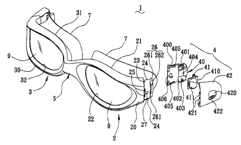
[0010] With reference to Fig. 1, swimming goggles 1 in accordance with
the present invention comprise a left frame 2, a right frame 3, a connecting
apparatus 5, pads 7, adjusting apparatuses 4 and straps 8 (shown in Figs. 4
and 5). In one embodiment, the connecting apparatus 5 is a nose support.
The left frame 2, the right frame 3, the connecting apparatus 5 and the pads
7 are integrally formed of soft material. The left frame 2 and the right frame
3 respectively have outer surfaces 20, 30 and inner surfaces 21, 31.
Receiving passageways 22, 32 are respectively defined between the outer
surfaces 20, 30 and the inner surfaces 21, 31 for accommodating lens 9. The
lens 9 are unitarily embedded between the outer surfaces 20, 30 and the
inner surfaces 21, 31 during manufacturing of the left frame 2 and the right
frame 3. The pads 7 are integrally formed on the inner surfaces 21, 31 of the
left frame 2 and the right frame 3. Engaging blocks 23 are respectively
formed on outward sides of the left frame 2 and the right frame 3. Each
engaging block 23 has a first engaging portion (not labeled) and a second
engaging portion (not labeled). In one embodiment, the first engaging
portion includes L-shaped jags 24 respectively in upward and downward
edges of the engaging block 23. The second engaging portion includes
positioning grooves 25 respectively adjacent to the left frame 2.and the right
frame 3. An arcuate spring 26 respectively extends outwardly from a side
edge of each engaging block 23. The arcuate spring 26 comprises two short
sides 261 connecting with the engaging block 23, and a long side 262. The
long side 262 transversely connects with ends of the short sides 261 and is
arcuate for providing resiliency. An engaging hole 27 is defined in the
engaging block 23.
[0011] Each adjusting apparatus 4 comprises a base 40, a fixing axis 41
and a cover 42. The base 40 has a first base wall 401, and a second base wall
402 opposing to each other. An axis hole 403 is defined respectively through
the first base wall 401 and the second base wall 402 for pivotably receiving
3
CA 02475157 2004-07-19
the fixing axis 41. A strap hole 404 is defined between the first base wall
401 and the second base wall 402 and adjacent the axis hole 403 for
movably receiving the strap 8. The adjusting apparatus 4 further comprises
an embedding portion for engaging with the engaging block 23. In one
embodiment the embedding portion has L-shaped projections 405 on the
base 40 for engaging the L-shaped jags 24 of the engaging block 23. The
base 40 forms a reinforce post 406 between the L-shaped projections 405 for
cooperating with the engaging hole 27 of the engaging block 23. The base
40 further defines locking holes 400 in sides thereof.
[0012) The fixing axis 41 is pivotably received in the axis hole 403. A
biasing arrn 410 is transversely extended from the fixing axis 41 for biasing
stop grooves 80 (shown in Figs. 4 and 5) of the strap 8. A button 411 is
transversely extended from the fixing axis 41 and is assembled with the
biasing arm 410. The button forms an inclined surface at a side thereof for
facilitating manual operation. Notably, further referring to Fig. S, the
distance T2 between the fixing axis 41 and the tip of the inclined surface of
the button 411 and is larger than the distance T1 between the fixing axis 41
and an extreme end of the biasing arm 410. Thus, the fixing axis 41 acting
as fulcrum, the button 411 is easily pressed to drive the biasing arm 410 to
move complying with leverage principle.
[0013] The cover 42 is fixed on the base 40 in assembly The cover 42
defines a through hole 420 for receiving the button 411, and forms a
plurality of barbs 421 at an edge thereof for locking the positioning grooves
25 of the engaging block 23. The cover 42 further forms locking posts 422
at sides thereof for cooperating with the locking holes 400 of the base 40.
[0014] In combination with Figs. 1-3, during manufacturing, the lens 9
are integrally embedded into the left frame 2 and the right frame 3, and
unitarily formed with the connecting apparatus 5 and the pads 7. Preferably,
4
CA 02475157 2004-07-19
height of the engaging blocks 23 are smaller than height of the left frame 2
and the right frame 3, and the adjusting apparatus 4 have tops and bottoms
respectively aligning with tops and bottoms of the left frame 2 and the right
frame 3 when the adjusting apparatus 4 are assembled to the swimming
goggles 1. In Figs. 1-3, only an adjusting apparatus 4 is an example for clear
description of assembly. The fixing axis 41 is assembled onto the axis hole
403. The button 411 is oriented beyond the long side 262 of the arcuate
spring 26. The L-shaped projections 405 latch with the L-shaped jags 24.
The reinforce post 406 is extended into the engaging hole 27. The engaging
posts 422 lock with the locking holes 400, whereby the cover 42 is
assembled onto the base 40.
[0015] As shown in Fig. 4, the strap 8 are extended through the strap hole
404. The biasing arm 410 abuts against a stop groove 80 of the strap 8,
wherein the strap 8 can move only in a single direction (as arrow shown in
Fig. 4). In other words, a user only can pull the strap 8 tighter at this
state.
Referring to Fig. 5, the button 411 is pressed downwardly Correspondingly,
the biasing arm 410 moves upwardly to disengage from the stop groove 80.
Meanwhile the long side 262 of the arcuate spring 26 is deformed and
reserves energy. At this state, the strap 8 can move in two directions (as
arrow shown in Fig. 5), in other words, a user only can freely pull the strap
8
tighter or looser. When pressure to the button 411 is removed, the arcuate
spring 26 drives the button 411 to return, and then the biasing arm 410 abuts
against a stop groove 80 of the strap 8 again.
[0016] The user makes the straps 8 looser before wearing the swimming
goggles, and then pulls the straps 8 directly and easily for proper
positioning
when wearing. On the other hand, when wearing, the user can press the
button 411 to make the straps 8 move a certain of length, and then pulls the
straps 8 to a proper position.
s
CA 02475157 2004-07-19
[0017] It is understood that the invention may be embodied in other
forms without departing from the spirit thereof. Thus, the present examples
and embodiments are to be considered in all respects as illustrative and not
restrictive, and the invention is not to be limited to the details given
herein.
6