Language selection

Search

Patent 2475483 Summary

Third-party information liability

Some of the information on this Web page has been provided by external sources. The Government of Canada is not responsible for the accuracy, reliability or currency of the information supplied by external sources. Users wishing to rely upon this information should consult directly with the source of the information. Content provided by external sources is not subject to official languages, privacy and accessibility requirements.

Claims and Abstract availability

Any discrepancies in the text and image of the Claims and Abstract are due to differing posting times. Text of the Claims and Abstract are posted:

  • At the time the application is open to public inspection;
  • At the time of issue of the patent (grant).
(12) Patent: (11) CA 2475483
(54) English Title: GAS FEED PIPE CONNECTING SCREW FOR CONTINUOUS CASTING NOZZLE
(54) French Title: VIS D'ASSEMBLAGE DE TUBE D'ALIMENTATION DE GAZ POUR BUSE DE COULEE EN CONTINU
Status: Deemed expired
Bibliographic Data
(51) International Patent Classification (IPC):
  • B22D 11/12 (2006.01)
  • B22D 11/117 (2006.01)
  • B22D 41/58 (2006.01)
(72) Inventors :
  • NAITO, SYOJIRO (Japan)
  • UCHIDA, KAZUHIDE (Japan)
(73) Owners :
  • AKECHI CERAMICS KABUSHIKI KAISHA (Japan)
(71) Applicants :
  • AKECHI CERAMICS KABUSHIKI KAISHA (Japan)
(74) Agent: OSLER, HOSKIN & HARCOURT LLP
(74) Associate agent:
(45) Issued: 2010-02-02
(22) Filed Date: 2004-07-22
(41) Open to Public Inspection: 2005-02-05
Examination requested: 2006-07-10
Availability of licence: N/A
(25) Language of filing: English

Patent Cooperation Treaty (PCT): No

(30) Application Priority Data:
Application No. Country/Territory Date
2003-286348 Japan 2003-08-05

Abstracts

English Abstract

A gas feed pipe connecting screw for a continuous casting nozzle is disclosed. The screw is mounted to the continuous casting nozzle formed with an axially extending ring-shaped slit substantially concentric with a nozzle bore. The screw connects to the nozzle a gas feed pipe blowing a gas into the slit. The screw includes a screw body having a gas feed hole formed through substantially its central portion, a flange fitted into a mounting hole formed in a side wall of the continuous casting nozzle, a male thread engaging a first female thread formed in the mounting hole, and a second female thread formed in the gas feed hole for connection of the gas feed pipe. The flange has a detent corner engaging mortar filling the mounting hole after having been fitted into the mounting hole.


French Abstract

L'invention concerne une vis d'assemblage de tube d'alimentation de gaz pour buse de coulée en continu. La vis est montée sur la buse de coulée continue formée avec une fente en forme d'anneau s'étendant axialement et sensiblement concentrique avec un alésage de buse. La vis relie à la buse un tuyau d'alimentation en gaz qui souffle un gaz dans la fente. La vis comprend un corps de vis ayant un orifice d'alimentation en gaz formé sensiblement à travers sa partie centrale, une bride fixée à un trou de montage formé dans une paroi latérale de la buse de coulée continue, un filetage mâle à mettre en prise avec un premier filetage femelle formé dans le trou de montage, et un deuxième filetage femelle formé dans l'orifice d'alimentation en gaz pour assurer la connexion du tuyau d'alimentation en gaz. La bride comporte un coin de cran qui entre en prise avec le mortier qui remplit le trou de montage après avoir été inséré dans le trou de montage.

Claims

Note: Claims are shown in the official language in which they were submitted.


CLAIMS

1. A gas feed pipe connecting screw for a continuous
casting nozzle, the screw being mounted to the continuous
casting nozzle formed with an axially extending ring-shaped
slit substantially concentric with a nozzle bore, the screw
connecting to the nozzle, a gas feed pipe blowing a gas into
the slit, the screw comprising:
a screw body having a gas feed hole formed through
substantially a central portion thereof;
a flange fitted into a mounting hole formed in a side
wall of the continuous casting nozzle;
a male thread engaging a first female thread formed in
the mounting hole; and

a second female thread formed in the gas feed hole for
connection of the gas feed pipe,
wherein the flange has a detent corner engaging mortar
filling the mounting hole after having been fitted into the
mounting hole, and the detent corner is inscribed in the
mounting hole.

2. A gas feed pipe connecting screw according to claim
1, wherein the flange has a polygonal planar shape with
apexes and the apexes serve as the detent corners.


7

Description

Note: Descriptions are shown in the official language in which they were submitted.


CA 02475483 2004-07-22

GAS FEED PIPE CONNECTING SCREW FOR CONTINUOUS CASTING NOZZLE
BACKGROUND OF THE INVENTION

1. Field of the invention

This invention relates to a gas feed pipe connecting screw
(hereinafter referred to as "connecting screw") mounted to a
continuous casting nozzle (hereinafter_referred to as "nozzle")
formed with an axially extending ring-shaped slit substantially
concentric with a nozzle bore for connecting to the nozzle a gas
feed pipe blowing a gas into the slit.

2. Description of the related art

A nozzle used in continuous casting is formed with an axially
extending ring-shaped slit substantially concentric with a
nozzle bore in order that inclusion adherent to an inner wall

of the nozzle during continuous casting may be eliminated. An
inert gas such as argon gas is blown into the slit. A gas feed
pipe feeding the inert gas is connected to a connecting screw
mounted on aside wali of the nozzle. JP-2001-219252-A discloses
such a connecting screw. A female thread is formed so as to be

continuous to a mounting hole of the nozzle side wall. A male
thread adapted to be into mesh engagement with the female thread
has three or more spot-welded portions w proj ecting from an outer
circumference thereof. The mounting hole is filled with mortar
y. The spot-welded portions are caused to engage the mortar y,
whereby detent is provided as shown in FIG. 4.

However, each spot-welded portion has a lower detent
strength than an integrally formed product. Moreover, a
constant detent strength is difficult to obtain by achieving a
1


CA 02475483 2004-07-22

uniform welding strength of each spot-welded portion, whereupon
the detent strength differs from one product to another. As a
result, the spot-welded portions would be broken due to high
temperature, vibration or the like, so that the connecting screw

would fall off from the nozzle. Additionally, a nut having a
detent structure is proposed. However, the nut cannot be
manufactured readily and the cost of the rlut is increased since
the nut has a complicated shape.

SUMMARY OF THE INVENTION

Therefore, an object of the present invention is to provide
a connecting screw which can be manufactured readily and has a
desirable detent effect.

To achieve the object, the present invention provides a gas
feed pipe connecting screw for a continuous casting nozzle. The
screw is mounted to the continuous casting nozzle formed with
an axially extending ring-shaped slit substantially concentric
with a nozzle bore. The screw connects to the nozzle a gas feed
pipe blowing a gas into the slit. The screw comprises a screw

body having a gas feed hole formed through substantially a central
portion thereof, a flange fitted into a mounting hole formed in
a side wall of the continuous casting nozzle, a male thread
engaging a first female thread formed in the mounting hole, and
a second female thread formed in the gas feed hole for connection

of the gas feed pipe. The flange has a detent corner engaging
mortar filling the mounting hole after having been fitted into
the mounting hole.

In the above-described connecting screw, the flange adapted
2


CA 02475483 2004-07-22

to be fitted into the mounting hole is formed with the detent
corner which engages the mortar filling the mounting hole after
the flange is fitted into the mounting hole, thereby providing
detent. The connecting screw can be manufactured readily since.

the flange is formed integrally with the screw body by forging
or the like. Furthermore, the connecting screw with high detent
performance can be provided at low costs.

In a preferred form, the flange has a polygonal plane with
apexes and the apexes serve as the detent corners. Consequently,
the detent performance can further be improved since the
engagement with the mortar is intensified.

In another preferred form, the detent corner is inscribed
in the mounting hole. Consequently, the detent performance can
further be improved by friction between the detent corners and
the inner circumferenti.al face of the mounting hole.

BRIEF DESCRIPTION OF THE DRAWINGS

Other objects, features and advantages of the present
invention will become clear upon reviewing the f.ollowing
description of an embodiment with reference to the accompanying
drawings, in which:

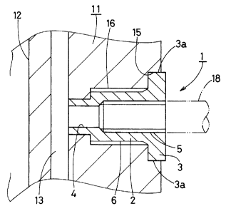
FIG. 1 is a schematic sectional view of the nozzle to which
the connecting screw in accordance with one embodiment of the
present invention is applied;

FIG. 2 is a partial sectional view of the nozzle to which
the connecting screw is mounted;

FIG. 3 is a front view of the nozzle to which the connecting
screw is mounted; and

3


CA 02475483 2004-07-22

FIG. 4 is a front view of a nozzle to which a conventional
connecting screw is mounted.

DETAILED DESCRIPTION OF THE INVENTION

One embodiment of the present invention will now be described
with reference to FIGS. 1 to 3. Referring to FIG. 1, a nozzle
11 to which a connecting screw 1 of the embodiment is mounted
is shown. The nozzle 11 has a nozzle bore 12 and an axially
extending ring-shaped slit 13 substantially concentric with the

nozzle bore 12. The nozzle 11 further has a mounting hole 14
formed in a side wall thereof. The mounting hole 14 communicates
with the slit 13. The mounting hole 14 includes a fitting hole
into which a flange 3 of the connecting screw 1 is fitted and
a female thread 16 formed so as to be continuous to the fitting

15 hole 15. The connecting screw 1 includes a male thread 6 engaging
the female thread 16.

A flange 3 having a hexagonal planar shape is formed
integrally with a screw body 2 by forgirig or the like. The screw
body 2 has a centrally located gas feed hole 4 formed therethrough.

The gas feed hole 4 is formed with a female thread 5 for connecting
a gas feed pipe. The screw body 2 further has a male thread 6
formed on an outer circumferential face thereof. The hexagonal
flange 3 has six apexes serving as detent corners 3a respectively.
The detent corners 3a are inscribed on the fitting hole 15 of
the mounting hole 14 as shown in FIG. 3.

The connecting screw 1 is mounted. to the mounting hole 14.
Gaps are defined between the flange 3 and the inner
circumferential face of the fitting hole 15. The gaps are filled
4


CA 02475483 2008-09-25

with refractory mortar 17. Aigas feed pipe 18 is connected to
the female thread 5 so that an inert gas such as argon gas is
fed to the slit 13 of the nozzle 11 during the continuous casting.

TABLE 1 shows comparison between the strength (torque value
( kg/cm2) of the connecting screw 1 thus constructed and the
strength of a conventional connecting screw s as shown in FIG.
4. In the conventional connecting screw s, an average strength
is 500 kg/cmZ at room temperature and 327 kg/cm2 at 1, 000 C. On
the other hand, the above-described connecting screw 1 has an

average strength of 1,220 kg/cm'` at a room temperature and 737
kg/cm2 at 1, 000 C. The values in the connecting screw 1 are twice
as large as those in the conventional connecting screw s or more.
TABLE 1
Strength Connecting screw 1 Connecting screw s
(torque in kg/cm2)
Room temperature 1,220 500
1, 000 C 737 327
Furthermore, differences in the strength are larger in the

conventional connecting screw s than in the connecting screw 1
as shown in TABLE 2.

TABLE 2

DIFFERENCES IN STRENGTH (TORQUE IN kg/cm2)
Connecting screw 1 Connecting screw s
Room temperature 1,140, 1,260, 1,260 530, 440, 550
1,00000 730, 740, 740 380, 260, 340

As described above, the connecting screw 1 of the embodiment
includes the flange 3 fitted into the fitting hole 15 of the
mounting hole 14. The flange 3 has the hexagonal planar shape.
The flange 3 engages the refractory mortar 17 filling the fitting
hole 15 after the flange 3 has been fitted into the fitting hole
5


CA 02475483 2004-07-22

15, thereby providing detent. Since the flange 3 is formed
integrally with the screw body 2 by the forging or the like, the
connecting screw 1 can be manufactured readily. Furthermore,
the connecting screw 1 with high detent performance can be

provided at low costs. The plane of the flange 3 should not be
limited to the hexagonal shape. The plane of the flange 3 may
be triangular, square or otherwise polygonal in shape, instead.
Each apex of the polygonal flange 3 serves as the detent corner
3a. Additionally, since the detent corners 3a are inscribed on

the fitting hole 15 of the mounting hole 14, the detent
performance can further be improved by friction between detent
corners 3a and the inner circumferential face of the fitting hole
15.

The foregoing description and drawings are merely
illustrative of the principles of the present invention and are
not to be construed in a limiting sense. Various changes and
modifications will become apparent to those of ordinary skill
in the art. All such changes and modifications are seen to fall
within the scope of the invention as defined by the appended
claims.

6

Representative Drawing
A single figure which represents the drawing illustrating the invention.
Administrative Status

For a clearer understanding of the status of the application/patent presented on this page, the site Disclaimer , as well as the definitions for Patent , Administrative Status , Maintenance Fee  and Payment History  should be consulted.

Administrative Status

Title Date
Forecasted Issue Date 2010-02-02
(22) Filed 2004-07-22
(41) Open to Public Inspection 2005-02-05
Examination Requested 2006-07-10
(45) Issued 2010-02-02
Deemed Expired 2016-07-22

Abandonment History

There is no abandonment history.

Payment History

Fee Type Anniversary Year Due Date Amount Paid Paid Date
Application Fee $400.00 2004-07-22
Registration of a document - section 124 $100.00 2004-11-12
Request for Examination $800.00 2006-07-10
Maintenance Fee - Application - New Act 2 2006-07-24 $100.00 2006-07-10
Maintenance Fee - Application - New Act 3 2007-07-23 $100.00 2007-07-18
Maintenance Fee - Application - New Act 4 2008-07-22 $100.00 2008-07-17
Maintenance Fee - Application - New Act 5 2009-07-22 $200.00 2009-06-09
Final Fee $300.00 2009-11-06
Maintenance Fee - Patent - New Act 6 2010-07-22 $200.00 2010-07-21
Maintenance Fee - Patent - New Act 7 2011-07-22 $200.00 2011-05-16
Maintenance Fee - Patent - New Act 8 2012-07-23 $200.00 2012-06-14
Maintenance Fee - Patent - New Act 9 2013-07-22 $200.00 2013-04-25
Maintenance Fee - Patent - New Act 10 2014-07-22 $250.00 2014-07-16
Owners on Record

Note: Records showing the ownership history in alphabetical order.

Current Owners on Record
AKECHI CERAMICS KABUSHIKI KAISHA
Past Owners on Record
NAITO, SYOJIRO
UCHIDA, KAZUHIDE
Past Owners that do not appear in the "Owners on Record" listing will appear in other documentation within the application.
Documents

To view selected files, please enter reCAPTCHA code :


To view images, click a link in the Document Description column. To download the documents, select one or more checkboxes in the first column and then click the "Download Selected in PDF format (Zip Archive)" or the "Download Selected as Single PDF" button.

List of published and non-published patent-specific documents on the CPD .

If you have any difficulty accessing content, you can call the Client Service Centre at 1-866-997-1936 or send them an e-mail at CIPO Client Service Centre.


Document
Description 
Date
(yyyy-mm-dd) 
Number of pages   Size of Image (KB) 
Abstract 2004-07-22 1 27
Description 2004-07-22 6 264
Claims 2004-07-22 2 41
Drawings 2004-07-22 3 46
Representative Drawing 2009-09-22 1 10
Representative Drawing 2005-01-10 1 6
Cover Page 2005-01-24 1 38
Drawings 2008-09-25 3 44
Description 2008-09-25 6 259
Claims 2009-07-15 1 26
Cover Page 2010-01-12 2 47
Correspondence 2004-09-03 1 27
Assignment 2004-07-22 2 119
Fees 2007-07-18 1 50
Assignment 2004-11-12 2 66
Prosecution-Amendment 2006-07-10 1 40
Fees 2006-07-10 1 42
Prosecution-Amendment 2008-04-02 2 58
Fees 2008-07-17 1 46
Prosecution-Amendment 2008-09-25 8 358
Prosecution-Amendment 2009-01-22 2 58
Prosecution-Amendment 2009-07-15 3 82
Fees 2009-06-09 1 54
Correspondence 2009-11-06 1 56
Fees 2010-07-21 1 47
Fees 2011-05-16 1 47
Correspondence 2014-11-13 1 24
Fees 2012-06-14 1 54
Fees 2013-04-25 1 54
Correspondence 2014-09-25 1 29
Fees 2014-07-16 1 44
Correspondence 2014-07-18 1 38