Language selection

Search

Patent 2475843 Summary

Third-party information liability

Some of the information on this Web page has been provided by external sources. The Government of Canada is not responsible for the accuracy, reliability or currency of the information supplied by external sources. Users wishing to rely upon this information should consult directly with the source of the information. Content provided by external sources is not subject to official languages, privacy and accessibility requirements.

Claims and Abstract availability

Any discrepancies in the text and image of the Claims and Abstract are due to differing posting times. Text of the Claims and Abstract are posted:

  • At the time the application is open to public inspection;
  • At the time of issue of the patent (grant).
(12) Patent: (11) CA 2475843
(54) English Title: TELESCOPING PLUNGER
(54) French Title: DEBOUCHOIR TELESCOPIQUE
Status: Deemed expired
Bibliographic Data
(51) International Patent Classification (IPC):
  • E03C 1/308 (2006.01)
  • A47K 11/10 (2006.01)
  • A47K 17/00 (2006.01)
  • B25G 1/04 (2006.01)
  • E03D 9/00 (2006.01)
(72) Inventors :
  • JIANG, WEI-XIN (China)
(73) Owners :
  • WAXMAN CONSUMER PRODUCTS GROUP INC. (United States of America)
(71) Applicants :
  • WAXMAN CONSUMER PRODUCTS GROUP INC. (United States of America)
(74) Agent: SMART & BIGGAR LP
(74) Associate agent:
(45) Issued: 2008-07-15
(22) Filed Date: 2004-07-27
(41) Open to Public Inspection: 2005-08-10
Examination requested: 2004-07-27
Availability of licence: N/A
(25) Language of filing: English

Patent Cooperation Treaty (PCT): No

(30) Application Priority Data:
Application No. Country/Territory Date
10/775,303 United States of America 2004-02-10

Abstracts

English Abstract

A toilet plunger assembly having telescopic features is disclosed. The plunger assembly includes a cup assembly, a tubular member and an elongated rod. The tubular member has a first end portion and a second end portion. The second end portion is fixed to the cup assembly. The elongated rod has a first end portion, a second end portion, and an outer diameter. The rod is slideably engaged within the tubular member such that the rod is moveable between a collapsed position and an extended position. In the collapsed position, the rod second end portion is removably joined to the cup assembly, while in the extended position, the rod second end portion is removably joined to the tubular member first end portion.


French Abstract

Un débouchoir pour toilettes ayant des caractéristiques télescopiques est décrit. Le débouchoir comprend une ventouse, un élément tubulaire et une tige allongée. L'élément tubulaire a une première partie d'extrémité et une seconde partie d'extrémité. La seconde partie d'extrémité est fixée à la ventouse. La tige allongée a une première partie d'extrémité, une seconde partie d'extrémité et un diamètre extérieur. La tige est engagée de manière coulissante dans l'élément tubulaire de telle sorte que la tige est mobile entre une position rentrée et une position sortie. Dans la position rentrée, la seconde partie d'extrémité de la tige est reliée de manière amovible à la ventouse, tandis que dans la position sortie, la seconde partie d'extrémité de tige est reliée de manière amovible à la première partie d'extrémité de l'élément tubulaire.

Claims

Note: Claims are shown in the official language in which they were submitted.


Claims


1. A toilet plunger assembly comprising

a) a cup assembly;

b) a tubular member having a first end portion and a second end portion,
wherein said second end portion engages said cup assembly, the first end
portion
including a threaded section, and

c) an elongated rod having a first end portion, a second end portion, said
rod being slideable within said tubular member such that said rod is moveable
between a collapsed position and an extended position, the second end portion
of
the rod including a first threaded section,

d) wherein said rod second end portion engages said cup assembly when
said rod is in said collapsed position and said rod second end portion engages
said
tubular member first end portion when said rod is in said extended position,
wherein
the first threaded section of the rod threadedly engages the threaded section
of the
first end portion of the tubular member in the extended position.


2. The plunger assembly of claim 1 wherein said tubular member second
portion comprises a threaded section.


6


3. The plunger assembly of claim 2 wherein said cup assembly comprises
an inverted suction cup, the plunger assembly having threads adapted to engage
the
threaded section of the tubular member second portion.


4. The plunger assembly of claim 1 wherein the threaded section of the
rod second end portion said tubular member first portion comprises a threaded
section disposed on an internal surface of said tubular member.


5. The plunger assembly of claim 1 wherein the first threaded section of
the rod second portion is disposed on an external surface of the rod.


6. The plunger assembly of claim 1 wherein said rod second portion
comprises a second threaded section adapted to engage a threaded opening of
the
cup assembly when the rod is in the collapsed position.


7. The plunger assembly of claim 6 wherein the second threaded section
of the rod second portion is disposed on the external surface of the rod
distal to the
first threaded section of the rod second portion.


8. The plunger assembly of claim 7 wherein said rod second end portion
comprises a stem extending axially from said rod and having an outer diameter
less
than an outer diameter of the rod, wherein said stem comprises the second
threaded
section disposed on an exterior surface of said stem.


7


9. The plunger assembly of claim 1 wherein said cup assembly comprises
an inverted suction cup and a connector, said connector adapted to engage said
rod
second end portion.


10. A toilet plunger assembly comprising:
a) a plunger cup; and

b) a handle assembly fixed to said cup, said handle assembly comprising:
(i) a tubular member having a first end portion, a second end portion, and an
axial
length, wherein said second end portion engages said cup, the first end
portion
including a threaded section; and (ii) an elongated rod comprising a first end
portion,
a second end portion, and an axial length, the second end portion of the rod
including
a first threaded section;

c) wherein said rod is slideable within said tubular member such that said
rod is moveable between a first position in which said rod second end portion
engages said cup and a second position in which said rod second end portion
engages said tubular member first end portion, such that an axial length of
the
plunger assembly is longer in said second position than in said first
position, wherein
the first threaded section of the rod threadedly engages the threaded section
of the
first end portion of the tubular member in the second position.


8


11. The plunger assembly of claim 10 wherein an axial rotation of said rod
with respect to said cup disengages said rod from the cup when in said first
position.


12. The plunger assembly of claim 10 wherein an axial rotation of said rod
with respect to said cup disengages said rod from the tubular member when in
said
second position.


13. The plunger assembly of claim 10 wherein said axial length of said rod
is longer than said axial length of said tubular member.


14. The plunger assembly of claim 10 wherein said cup comprises an
inverted suction cup and a connector, said connector adapted to engage said
rod
second end portion when in the first position.


9


15. A toilet plunger assembly comprising:
a) an inverted suction cup,

b) a connector having a first end and a second end, said second end
having an inner opening with first and second threaded sections disposed on an

interior surface thereof;

c) a tubular member comprising a first end, a second end, an interior
surface and an exterior surface, said first end having a threaded section
disposed on
said interior surface thereof and said second end having threaded section
disposed
on said exterior surface thereof, said second end threaded section adapted to
engage the first threaded section of said connector second end, and

d) an elongated rod comprising a first end, a second end, an outer
diameter, and an exterior surface, said second end having distal and proximal
threaded sections disposed on an exterior surface thereof, said distal
threaded
section adapted to engage the second threaded section of said connector second

end, and said proximal threaded section adapted to engage the threads of said
tubular member first end;

e) wherein said rod is slideably engaged within said tubular member from
a collapsed position to an extended position


10


16. The plunger assembly of claim 15 wherein the first threaded section of
the connector second end is of a greater diameter than the second threaded
section
of said connector second end.


17. The plunger assembly of claim 15 wherein said rod second end
comprises a stem portion extending axially from said rod having an outer
diameter
less then said rod outer diameter, the distal threaded section being disposed
on the
stem portion.


18. The plunger assembly of claim 15 wherein an axial rotation of said rod
with respect to said cup disengages said rod from the cup when in said
collapsed
position.


19. The plunger assembly of claim 15 wherein an axial rotation of said rod
with respect to said cup disengages said rod from the tubular member when in
said
extended position.


11


20. A toilet plunger assembly comprising:
a) a base assembly comprising:

i) an inverted suction cup; and

ii) a tubular member having a first end portion and a second
end portion, wherein said second end portion engages a top surface of said
cup,
the first end portion including a threaded section; and

b) a handle assembly comprising:

i) an elongated rod having a first end portion and a second end
portion, said rod being slideable within said tubular member such that said
rod is
moveable between a collapsed position and an extended position, the second
end portion. of the rod including a first threaded section; and

ii) a grippable handle fixed to said rod first end portion;

c) wherein said rod second end portion engages said base assembly when
said rod is in said collapsed position and said rod second end portion engages

said tubular member first end portion when said rod is in said extended
position,
wherein the first threaded section of the rod threadedly engages the threaded
section of the first end portion of the tubular member in the extended
position,


12


21. A toilet plunger assembly comprising:

a) a cup assembly including an opening defining a threaded section;
b) a tubular member having a first end portion and a second end
portion, wherein the second end portion engages the cup assembly; and

c) an elongated rod having a first end portion, a second end portion,
the rod being slideable within the tubular member such that the rod is
moveable
between a collapsed position and an extended position, the second end portion
of the rod including a threaded section;

d) wherein the rod second end portion engages the cup assembly
when the rod is in the collapsed position, wherein the threaded section of the
rod
threadedly engages the threaded section of the cup assembly in the collapsed
position; and

e) the rod second end portion engages the tubular member first end
portion when the rod is in the extended position.


13

Description

Note: Descriptions are shown in the official language in which they were submitted.


CA 02475843 2004-07-27
16-584 .
TELESCOPING PLUNGER
s Field of the Invention
The present invention relates to a toilet plunger and more particularly to a
toilet
plunger having telescopic features allowing for storage in confined areas.
Background of the Invention
to Toilet plungers are well known and widely used in bathrooms of residences,
office
buildings, retail establishments and restaurants. Most conventional plungers
include a plunger
cup mounted to a fixed length handle. It is further known and appreciated that
the
conventional use of a plunger is to unclog the exit piping leading from a
toilet to a sewer
system or other types of collection system. This use inherently creates both
sanitary and
15 aesthetic issues for any party responsible for bathroom maintenance.
It is common to store a plunger on the floor adjacent to a toilet in a
conveniently
locatable site. However, a plunger is unsightly and may contrast to the
decorum of certain
bathrooms. As a result, some plungers are stored in closets or in other
enclosed areas.
However, the length of a typical plunger handle prohibits storage of a plunger
in many areas.
2o Further, the conventional size of a plunger makes its presence in most
bathrooms quite
apparent, i.e., it is difficult to hide in a corner, for example.
In light of the prior art problems discussed, it would be desirable to have a
toilet
plunger that features a telescopic handle. Further, it would be advantageous
to have a
telescopic plunger that is operational without a user having to touch the
toilet plunger cup.
25 The present invention provides a new and improved toilet plunger having a
telescopic
handle. The present invention uses a two part handle design wherein the device
is
transferable between an extended position and a collapsed position by
manipulation of the
handle.


CA 02475843 2004-07-27
Summaxy of the Invention
In an illustrated embodiment of the invention, a toilet plunger featuring a
telescopic
handle is disclosed. It should be understood that the illustration of a
plunger in the
accompanying drawings includes a conventional cup for exemplary purposes only
and the
invention may be practiced with the use of toilet plungers having new,
improved or otherwise
alternative cup designs.
A toilet plunger assembly of the present invention includes a cup assembly, a
tubular
member, and a elongated rod. The tubular member has a first end portion and a
second end
portion, wherein the second end portion is fixed to the cup assembly. The
elongated rod has a
1o first end portion, a second end portion, and an outer diameter. The rod is
slideably engaged
within the tubular member such that the rod is moveable between a collapsed
position and an
extended position. Further, the rod second end portion is removably joined to
the cup
assembly when the rod is in the collapsed position. Alternatively, the rod
second end portion
is rernovably joined to the tubular member first end portion when the rod is
in the extended
position.
The tubular member second portion may include a threaded section disposed on
an
exterior surface of the tubular member. As such, the cup assembly may include
an inverted
suction cup having threads adapted to engage the threads of the tubular member
second
portion.
The tubular member first portion may include a threaded section disposed on an
interior surface of the tubular member. As such, the rod second portion may
include a
threaded section adapted to engage the threads of the tubular member first
portion.
The rod second end portion may include a stem extending axially from the rod
and
having a outer diameter less than the rod outer diameter, wherein the stem
includes a threaded
section disposed on an exterior surface of the stem. As such, the cup assembly
may include
an,inverted suction cup and a connector adapted to engage the rod second end
portion.
Further features and advantages of the invention will become apparent from the
following detailed description made with reference to the accompanying
drawings.


CA 02475843 2004-07-27
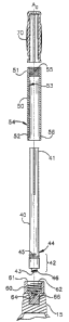
Brief Description of the Drawings
Figure 1 is a perspective view of a telescoping plunger assembly constructed
in
accordance with one embodiment of the present invention;
Figure 2 is an exploded cross sectional view of several parts of the plunger
shown in
Figure 1;
Figure 3 is a cross-sectional view of the plunger shown in Figure 1 as seen
approximately from a plane taken along the lines 3-3 of Figure I, showing the
plunger handle
in an extended position; and
Figure 4 is a cross-sectional view of the plunger of Figure I, showing the
plunger
l0 handle in a collapsed position.
Detailed Description of the Invention
Referring now to the drawings, a plunger assembly 10 constructed in accordance
with
one embodiment of the present invention is illustrated. The phznger assembly
10 has
telescopic features allowing for storage in confined areas. The plunger
assembly as shown
includes a conventional inverted suction cup 15. It should be understood that
the illustration
of an inverted suction cup is for exemplary purposes only and the invention
may be practiced
with the use of various suction apparatus.
Referring now to Figure l, a telescoping plunger assetrtbly 10 is illustrated.
The
2o plunger assembly includes a handle assembly 30 mounted to the inverted
suction cup 15. As
shown in Figure 2, the handle assembly 30 includes an elongated solid rod 40,
a hollow
tubular member 50, and a grippable handle 70. The components of the plunger 10
are
cooperatively mounted along a center axis A~ as best shown in. Figures 2-4.
As shown in Figure 1, the suction cup 15 includes a top surface 20. The top
surface
includes mating means allowing for engagement to a plunger connector 60. The
mating of the
plunger connector 60 to the plunger 20 is best shown in Figure 2. It should be
understood by
those with ordinary skill in the ark, that the present invention can be
practiced-without the use
of a separate plunger connector 60, i.e., the plunger cup 15 itsE;lf may
include mating means.
It should also be understood by those with ordinary skill in the art that the
tubular member 50,
3o the plunger connector 60, and the inverted plunger cup 15 may be uniformly
made as one
piece in the practice of the present invention.
3
..,. .. .... _. _ .._. .. . ~...~,~. ~,~.,,.v~:y~ .~.~ M-...~_ _..._ w.~.afi"
~xa.~~,~....__.___..___ _ .


CA 02475843 2004-07-27
Referring now to Figure 2, an exploded cross sectional View of several parts
of the
plunger assembly 10 are shown. As discussed, the plunger assembly 10 includes
an elongated
solid rod 40 having a first end portion 41 and a second end portion 42. As
shown in Figure 2,
an extended stem 43 protrudes axially from the second end portion 42. The
second end
portion 42 further includes several threaded connections on an external
surface 44 of the
second end portion 42. With respect to the first end portion 41, a proximal
threaded section
45 and a distal threaded section 46, or stem threaded section, are disposed on
the exterior
surface 44. As can be appreciated by viewing Figures 3-4, the elongated rod 40
has a limited
outer diameter allowing for insertion through the hollow tubular member 50.
As shown in the Figures, the handle 70 is fixedly mounted to the first end
portion 41
of the rod 40 by adhesive or other suitable method. It should also be
understood by those with
ordinary skill in the art that the rod 40 and the handle 70 may be uniformly
made as one piece
in the practice of the present invention.
The tubular member 50 also includes a first end portion 51 and a second end
portion
52. An internal surface 53 defines an inner diameter and as external surface
54 defines an
outer diameter. The tubular member includes a female thzeaded connection 55 at
the first end
portion and a male threaded connection 56 at the second end portion.
Still referring to Figure 2, the plunger connector 60 is shown in detail. An
inner
circular-shaped opening 61 is disposed distal to the elongated .rod 40 with
respect to the
2o suction cup 15. Disposed in the inner opening 61 is a first inner threaded
section 62 and a
second inner threaded section 64. An external threaded connection 64 mates
with threads
disposed in the inverted plunger suction cup 15 as shown.
Referring now to Figures 3 and 4, rivo cross sectional views of the plunger
shown in
Figure 1 as seen approximately along a plane taken along the lines 3-3 are
shown. In Figure
3, the plunger is shown in an extended position and in Figure 4 the plunger is
shown in a
collapsed position. In between these two positions, the elongated rod 40 is
engaged and
slideable within the tubular member 50. In operation of the plunger assembly,
rotation of the
grippable handle 70 is used to first, lock the assembly in either the extended
or collapsed
position, and second, unlock the assembly from either the collapsible or
extendable position.
3o It should be understood by others with ordinary skill in the art that
modifications that
incorporate either clockwise or counterclockwise rotation for locking or
unlocking means may
4
.~..."...,.,.... . ~.eu,. .;u.,. v..,z'.vmx "a,v-.;~~.,~y,~,,. y~..~,y.~r
4~'., ,",C,v~gpeW a...~rn+.,».-.....~--...."..,
.,a.,.u~mnew,;,..nrt~w.*a_qseq.p,,~,~.",w,. .~»w......~..--......~_._._......,
~....-.,_~ e~
E


CA 02475843 2004-07-27
be used in the practice of the present invention.
Referring specifically now to Figure-3, the handle assembly 30 is shown locked
in an
extended position. As such, the proximal threaded section 45 of the elongated
rod 40 is
shown engaged with the female threaded section 5S of the first end portion 51
of the tubular
s member 50. The present invention allows for the connection made to be of
sufficient strength
and stability to allow for conventional use of the plunger to unclog a toilet.
In other words,
axial pressure caused by a user's manipulation of the grippable handle 70 will
not cause the
connection made between the second end portion of the elongated rod 40 and the
first end
portion of the tubular member 50 to become disengaged.
io Referring now specifically to Figure 4, the handle assembly 30 is shown in
a collapsed
position. As such, the distal or stem threads 46 of the second end portion 42
of the elongated
rod 40 are shown engaged with th.e second inner threaded section 64 of the
plunger connector
60. While in a collapsed position, a user may transport the plunger assembly
10 by gripping
on the handle 70. The connection made between the elongated. rod 40 and the
plunger
15 connector 50 is sufficient to allow for transportation without the rod
becoming disengaged.
Referring again to Figure 3, an abutment face 58 of the tubular member and a
handle
abutment face 72 of the handle 70 are shown. These two faces 58, 72 are shown
engaged in
Figure 3 in a collapsible position. This feature provides guidance to a user
to determine when
sufficient locking has occurred to achieve the collapsed position.
2o While a single embodiment of the invention has been illustrated and
described in
considerable detail, the present invention is not to be considered limited to
the precise
construction disclosed. Various adaptations, modifications ar.~d uses of the
invention may
occur to those with ordinary skill of the art to which the invention relates.
It is the intention
of the applicant to cover all such adaptations, modifications aid uses falling
within the scope
25 and spirit of the claims filed herewith.
5
..~.~"~~~

Representative Drawing
A single figure which represents the drawing illustrating the invention.
Administrative Status

For a clearer understanding of the status of the application/patent presented on this page, the site Disclaimer , as well as the definitions for Patent , Administrative Status , Maintenance Fee  and Payment History  should be consulted.

Administrative Status

Title Date
Forecasted Issue Date 2008-07-15
(22) Filed 2004-07-27
Examination Requested 2004-07-27
(41) Open to Public Inspection 2005-08-10
(45) Issued 2008-07-15
Deemed Expired 2022-07-27

Abandonment History

There is no abandonment history.

Payment History

Fee Type Anniversary Year Due Date Amount Paid Paid Date
Request for Examination $800.00 2004-07-27
Registration of a document - section 124 $100.00 2004-07-27
Application Fee $400.00 2004-07-27
Maintenance Fee - Application - New Act 2 2006-07-27 $100.00 2006-06-12
Maintenance Fee - Application - New Act 3 2007-07-27 $100.00 2007-04-20
Final Fee $300.00 2008-04-18
Maintenance Fee - Patent - New Act 4 2008-07-28 $100.00 2008-07-17
Maintenance Fee - Patent - New Act 5 2009-07-27 $200.00 2009-06-30
Maintenance Fee - Patent - New Act 6 2010-07-27 $200.00 2010-06-30
Maintenance Fee - Patent - New Act 7 2011-07-27 $200.00 2011-06-30
Maintenance Fee - Patent - New Act 8 2012-07-27 $200.00 2012-07-02
Maintenance Fee - Patent - New Act 9 2013-07-29 $200.00 2013-07-01
Maintenance Fee - Patent - New Act 10 2014-07-28 $250.00 2014-07-21
Maintenance Fee - Patent - New Act 11 2015-07-27 $250.00 2015-07-20
Maintenance Fee - Patent - New Act 12 2016-07-27 $250.00 2016-07-25
Maintenance Fee - Patent - New Act 13 2017-07-27 $250.00 2017-07-24
Maintenance Fee - Patent - New Act 14 2018-07-27 $250.00 2018-07-23
Maintenance Fee - Patent - New Act 15 2019-07-29 $450.00 2019-07-19
Maintenance Fee - Patent - New Act 16 2020-07-27 $450.00 2020-07-17
Maintenance Fee - Patent - New Act 17 2021-07-27 $459.00 2021-07-23
Owners on Record

Note: Records showing the ownership history in alphabetical order.

Current Owners on Record
WAXMAN CONSUMER PRODUCTS GROUP INC.
Past Owners on Record
JIANG, WEI-XIN
Past Owners that do not appear in the "Owners on Record" listing will appear in other documentation within the application.
Documents

To view selected files, please enter reCAPTCHA code :


To view images, click a link in the Document Description column. To download the documents, select one or more checkboxes in the first column and then click the "Download Selected in PDF format (Zip Archive)" or the "Download Selected as Single PDF" button.

List of published and non-published patent-specific documents on the CPD .

If you have any difficulty accessing content, you can call the Client Service Centre at 1-866-997-1936 or send them an e-mail at CIPO Client Service Centre.


Document
Description 
Date
(yyyy-mm-dd) 
Number of pages   Size of Image (KB) 
Abstract 2004-07-27 1 23
Description 2004-07-27 5 313
Claims 2004-07-27 4 187
Drawings 2004-07-27 3 62
Representative Drawing 2005-07-13 1 6
Cover Page 2005-08-19 2 38
Claims 2007-08-08 8 197
Cover Page 2008-06-17 2 39
Assignment 2004-07-27 4 192
Fees 2006-06-12 1 29
Prosecution-Amendment 2007-03-21 2 90
Fees 2007-04-20 1 28
Prosecution-Amendment 2007-08-08 24 738
Correspondence 2008-04-18 1 34