Language selection

Search

Patent 2475858 Summary

Third-party information liability

Some of the information on this Web page has been provided by external sources. The Government of Canada is not responsible for the accuracy, reliability or currency of the information supplied by external sources. Users wishing to rely upon this information should consult directly with the source of the information. Content provided by external sources is not subject to official languages, privacy and accessibility requirements.

Claims and Abstract availability

Any discrepancies in the text and image of the Claims and Abstract are due to differing posting times. Text of the Claims and Abstract are posted:

  • At the time the application is open to public inspection;
  • At the time of issue of the patent (grant).
(12) Patent Application: (11) CA 2475858
(54) English Title: ADD/DROP NODE FOR AN OPTICAL COMMUNICATIONS NETWORK
(54) French Title: NOEUD D'ADJONCTION/ABANDON POUR RESEAU DE COMMUNICATIONS OPTIQUES
Status: Dead
Bibliographic Data
(51) International Patent Classification (IPC):
  • H04J 14/02 (2006.01)
(72) Inventors :
  • CLARINGBURN, HARRY RICHARD (United Kingdom)
(73) Owners :
  • ERICSSON AB (Sweden)
(71) Applicants :
  • MARCONI UK INTELLECTUAL PROPERTY LTD. (United Kingdom)
(74) Agent: KIRBY EADES GALE BAKER
(74) Associate agent:
(45) Issued:
(86) PCT Filing Date: 2003-03-14
(87) Open to Public Inspection: 2003-09-25
Examination requested: 2004-10-29
Availability of licence: N/A
(25) Language of filing: English

Patent Cooperation Treaty (PCT): Yes
(86) PCT Filing Number: PCT/GB2003/001082
(87) International Publication Number: WO2003/079597
(85) National Entry: 2004-08-11

(30) Application Priority Data:
Application No. Country/Territory Date
0206049.9 United Kingdom 2002-03-14

Abstracts

English Abstract


A 1550nm DWDM optical communications network has a 1300nm remote node added to
which a small number of channels can be added or dropped. The additional node
includes dual wavelength couplers to enable 1300nm wavelength signals to be
added or dropped. The 1300nm signals are demultiplexed using a WDM filter and
connected into the transponders of the 1550nm nodes for transportation around
the node. Signals for the remote network are converted to 1300nm signals at
the 1550nm node transponders and multiplexed onto the network to be dropped to
the network node transponder.


French Abstract

Selon cette invention, un réseau de communications optiques à multiplexage en longueur d'onde dense de 1550 nm possède un noeud additionnel hors site 1300 nm à partir duquel il est possible d'ajouter ou d'abandonner un petit nombre de canaux. Le noeud additionnel comprend des coupleurs bifréquence permettant d'ajouter ou d'abandonner des signaux de 1300 nm. Une fois que les signaux de 1300 nm sont démultiplexés au moyen d'un filtre de multiplexage en longueur d'onde, ils sont raccrochés dans les transpondeurs des noeuds 1550 nm en vue d'un transport contournant le noeud. Les signaux du réseau hors site sont abaissés à la fréquence de 1300 nm au niveau des transpondeurs du noeud 1550 nm et raccrochés par multiplexage sur le réseau de façon à être abandonnés au transpondeur du noeud du réseau.

Claims

Note: Claims are shown in the official language in which they were submitted.


7


CLAIMS


1. A DWDM optical communications network having a plurality of network nodes
each for adding and dropping signals to the network at a first set of
wavelengths, and a
further node for adding and dropping signals at a second set of wavelengths
not included in
the first set of wavelengths, the further node being arranged between adjacent
nodes of the
plurality of nodes, the further node comprising a first dual wavelength
coupler for dropping
signals at the second set of wavelengths from the network and a second dual
wavelength
coupler for adding a second set of wavelengths onto the network, and wherein
the adjacent
nodes of the plurality of nodes include transponders for transmitting signals
received at the
second set of wavelengths onto the network at the first set of wavelengths,
and receiving
from the network, signals at the first set of wavelengths to be passed to the
further node at
the second set of wavelengths.

2. A DWDM optical communications network according to claim 1, wherein the
network between the dual wavelength couplers carries signals at the first and
second set of
wavelengths.

3. A DWDM optical communications network according to claim 1, wherein the
further node comprises means for splitting a signal multiplex received from
the network in
a plurality of separate channels each at one of the second set of wavelengths.

4. A DWDM optical communications network according to claim 3, wherein the
means for splitting comprises an optical demultiplexer.


8


5. A DWDM optical communications network according to any of claims 1 to 4,
wherein the further node comprises means for combining signal channels at
individual
wavelengths of the second set of wavelengths for addition onto the network.

6. A DWDM optical communications network according to claim 5, wherein the
combining means comprises a multiplexer.

7. A DWDM optical communications network according to any preceding claim,
wherein the transponders at the adjacent nodes of the plurality of network
nodes comprises
means for converting traffic received at the second set of wavelengths into an
electrical
signal, and means for converting the electrical signal to an optical signal at
one of the first
set of wavelengths.

8. A DWDM optical communications network according to any preceding claims,
wherein the transponders at the adjacent nodes of the plurality of network
nodes comprises
means for band pass filtering traffic received from the network to select a
single channel,
means for converting the selected channel into an electrical signal and means
for
converting the electrical signal to a grey optical signal at the second set of
wavelengths.

9. A DWDM optical communications network according to any preceding claim,
wherein the further node comprises a transponder comprising means for
converting traffic
for addition to the network at the second set of wavelengths into an
electrical signal, and
means for converting the electrical signal as a WDM signal at the second set
of
wavelengths.


9


10. A DWDM optical communications network according to any preceding claims,
wherein the first set of wavelengths is based on 1550nm and the second set of
wavelengths
is based on 1300nm.

11. A 1300nm wavelength WDWM node for use with a 1550nm wavelength DWDM
optical communications network, the WDWM node comprising a pair of 1300/1550nm
couplers for adding and dropping 1300nm signals to and from a path of the
network, a
1300nm multiplexer for multiplexing channels of the WDM signal for addition to
the
network and a demultiplexer for demultiplexing 1300nm signals from the network
to
provide a plurality of WDM channels.


Description

Note: Descriptions are shown in the official language in which they were submitted.


CA 02475858 2004-08-11
WO 03/079597 PCT/GB03/01082
1
ADD/DROP NODE FOR AN
OPTICAL COMMUNICATIONS NETWORK
This invention relates to optical communications networks, and in particular
to add/drop
nodes for adding signals to, and dropping signals from, the network.
Modern optical communications networks modulate traffic using C band
wavelengths based on 1550nm. A typical network operates at lOGbit with network
nodes
spaced many kilometres apart. Photonic add/drop equipment for these networks
is very
expensive. Moreover the optical signal to noise ratio (OSNR) degrades as
additional nodes
are added. Deploying a large number of nodes in a ring network will lead to
very poor
performance. Because of these dual constraints, if only a small number of
channels are
to required to be added or dropped at a node it may not be economical or even
desirable from
the point of view of the OSNR to include the node on the network.
There is, therefore, a problem in adding nodes requiring small number of
channels,
both from the point of view of OSNR and expense.
The present invention aims to overcome that problem. Broadly, the invention
provides a remote node operating with a different set of wavelength signals in
conjunction
with the major add/drop nodes of the network. The major nodes are used to
transport
add/drop traffic from the remote node around the network.
More specifically, there is provided a DWDM optical communications network
having a plurality of network nodes each for adding and dropping signals to
the network at


CA 02475858 2004-08-11
WO 03/079597 PCT/GB03/01082
2
a first set of wavelengths, and a further node for adding and dropping signals
at a second
set of wavelengths, the further node being arranged between adjacent nodes of
the plurality
of nodes, the further node comprising a first dual wavelength coupler for
dropping signals
at the second set of wavelengths from the network and a second dual wavelength
coupler
for adding a second set of wavelengths onto the network, and wherein the
adjacent nodes
of the plurality of nodes include transponders for transmitting signals
received at the
second set of wavelengths onto the network at the first set of wavelengths,
and receiving
from the network, signals at the first set of wavelengths to be passed to the
further node at
the second set of wavelengths.
Embodiments of the invention have the advantage that a low cost remote node
can
be constructed using components for a 1300nm network which are much cheaper
than
1550nm DWDM network components. The remote node is only needed to drop/add a
few
channels. As the wavelengths of the 1300nm signals are so far from the 1550nm
signals,
any noise from the remote node signal does not affect the 1550nm OSNR.
Preferably, the transponders of adjacent network nodes include means for
converting signals at the second set of wavelengths used by the remote node,
preferably
1300nm, to the first set of wavelengths used by the network nodes, preferably
1550nm, and
2o vice versa. Lower quality non-wavelength locked lasers may be used to
convert to the
second set of wavelengths further reducing cost.
An embodiment of the invention will now be described, by way of example only,
and with reference to the accompanying drawings, in which:


CA 02475858 2004-08-11
WO 03/079597 PCT/GB03/01082
3
Figure 1 is a schematic view of a ring network including a remote add/drop
node
embodying the invention;
Figure 2 shows the remote node an adjacent network nodes in more detail; and
Figure 3 shows the remote node transponder.
Figure 1 illustrates a ring network 10 such as a Marconi PMA 32 optical
network
which carries lOGbids traffic using a 32 channel multiplex based on a carrier
wavelength
of 1550nm. A number of add/drop nodes 12 to 18 are spaced at intervals of
several
kilometres, say about 100 km around the network. A remote node 20 is arranged
between
two of the add/drop nodes 16, 18. The remote node can be seen as a cut down
version of
the add/drop nodes 12 to 18 which operates at a different carrier wavelength,
for example
1300nm and which is invisible to the 1550nm DWDM (dense wave division
multiplex)
network. The components required to build a 1300nm node are very much cheaper
than
those required for a 1550nm node and noise on the 1300nm node will not affect
the OSNR
of the 1550nm network.
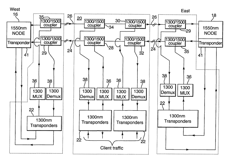
Figure 2 shows the remote node in more detail. The node is arranged between
two
main photonic add/drop nodes 16, 18 of the 1550nm network. That network is a
two fibre
network with one fibre 26 carrying traffic in a WestlEast direction (W/E) and
the other
fibre 24 carrying traffic in the East/West (E/W) direction. East and West are
used
conventionally and do not correspond to geographical east and west.


CA 02475858 2004-08-11
WO 03/079597 PCT/GB03/01082
4
The remote node 20 comprises low cost 1300nm transponders 22 whose
wavelengths are such that they can be used with a coarse WDM filter system.
The outputs
from the transponders are combined and coupled onto the main 1550nm network
fibres 24,
26 using low loss 1300/1550nm couplers 28, 30. For protection purposes the
1300nm
signals are transported to the main network nodes 16, 18 where the signal is
demultiplexed
using a further 1300/1550nm coupler 29. Using another coarse WDM filter, shown
as
demultiplexer 38 the 1300nm composite signal is demultiplexed back into its
individual
channels which are connected into the transponders 41 of the main network node
via
1300nm transponders 22 for transportation around the ring. Signals dropped by
the main
to network node undergo the reverse procedure with signals from the 1500nm
transponders
being passed to 1300nm transponders 22, multiplexed by a 1300nm signal
multiplexer 36
and coupled onto the fibres 24, 26 using a further coupler 35.
Thus, in Figure 2, client traffic at the remote node is received at or
transmitted from
one of a pair of W/E, E/W transponders 22. Traffic to be added to the network
is
multiplexed by a 1300nm signal multiplexer 36 and the 1300nm signal multiplex
is added
to the network by 1300/1550nm add coupler 28 for traffic to be added to the
E/W fibre 24
and by 1300/1550nm add coupler 30 for traffic to be added to the W/E fibre 26.
Traffic to
be dropped from the network to the transponders 22 is dropped by a 1300/1550
splitter
coupler 32, 34 on each of the two fibres on the network and then demultiplexed
by
demultiplexers 38 to restore the individual channels which are received by the
transponders
22.


CA 02475858 2004-08-11
WO 03/079597 PCT/GB03/01082
Thus, each of the fibres has a pair 1300/1550nm couplers arranged between
adjacent 1550nm nodes. Traffic on the fibre between the couplers will be mixed
1550nm
and 1300nm traffic. However, the noise generated by the 1300nm components will
not
affect the 1550nm network and so the noise budget of the network will not be
affected by
5 the remote node.
Traffic which has been placed on the network from the remote node cannot be
transported around the network as a 1300nm signal due to fibre loss and
amplifier
limitations. Thus, considering the W/E path 26, traffic is coupled onto the
fibre 26 by add
coupler 30. The 1300nm traffic is dropped by sputter coupler 34, demultiplexed
by the
multiplexer 38 into the individual channels. These channels are passed to the
main 1550nm
network node transponders where they are transported around the ring network
as 1550nm
signals.
Figure 3 shows the transponder at the 1550nm nodes required to add and drop
the
1300nm signal to and from the network. On the add side, a grey, non wavelength
specific
signal is received and is converted to an electrical signal by photo diode 50
and amplified
by amplifier 52.
At 54, after retiming, the signal may be further processed to add error
detection and
system management information before being re-transmitted at the required
wavelength by
laser 56.


CA 02475858 2004-08-11
WO 03/079597 PCT/GB03/01082
6
On the drop side, a received signal is converted to an electrical signal by a
photodiode 59 and an amplifier 60. After retiming at 62, the signal may be
further
processed to detect errors and management information. The signal is converted
back to an
optical signal by laser 64. This is a grey laser which is inexpensive and
which outputs a
grey signal to the client.
At the remote node, the lasers used in the transponders can be non-wavelength
locked and directly modulated. As these nodes only use a small number of
channels, which
is why a full 1550nm node is not needed, they may be WDM transponders instead
of the
dense WDM required on the main network. As the channels are spaced further
apart on a
WDM network than on a DWDM network, controlling drift of the laser with
temperature
may not be required, further simplifying the construction.
Thus, the embodiment described further provides a low cost remote node for an
optical network that is suitable for use where the channel requirement is not
large enough
to warrant a full node. The node functions at a different wavelength to the
main network so
that any noise at that wavelength introduced onto the network does not affect
the OSNR of
the main network.
Various modifications to the embodiment described are possible and will occur
to
those skilled in the art without departing from the invention which is defined
by the
following claims.

Representative Drawing
A single figure which represents the drawing illustrating the invention.
Administrative Status

For a clearer understanding of the status of the application/patent presented on this page, the site Disclaimer , as well as the definitions for Patent , Administrative Status , Maintenance Fee  and Payment History  should be consulted.

Administrative Status

Title Date
Forecasted Issue Date Unavailable
(86) PCT Filing Date 2003-03-14
(87) PCT Publication Date 2003-09-25
(85) National Entry 2004-08-11
Examination Requested 2004-10-29
Dead Application 2010-03-15

Abandonment History

Abandonment Date Reason Reinstatement Date
2009-03-16 FAILURE TO PAY APPLICATION MAINTENANCE FEE

Payment History

Fee Type Anniversary Year Due Date Amount Paid Paid Date
Registration of a document - section 124 $100.00 2004-08-11
Application Fee $400.00 2004-08-11
Request for Examination $800.00 2004-10-29
Registration of a document - section 124 $100.00 2004-11-03
Maintenance Fee - Application - New Act 2 2005-03-14 $100.00 2005-03-11
Maintenance Fee - Application - New Act 3 2006-03-14 $100.00 2006-03-13
Registration of a document - section 124 $100.00 2006-11-08
Maintenance Fee - Application - New Act 4 2007-03-14 $100.00 2007-03-13
Maintenance Fee - Application - New Act 5 2008-03-14 $200.00 2008-02-19
Owners on Record

Note: Records showing the ownership history in alphabetical order.

Current Owners on Record
ERICSSON AB
Past Owners on Record
CLARINGBURN, HARRY RICHARD
M (DGP1) LTD
MARCONI COMMUNICATIONS LIMITED
MARCONI UK INTELLECTUAL PROPERTY LTD.
Past Owners that do not appear in the "Owners on Record" listing will appear in other documentation within the application.
Documents

To view selected files, please enter reCAPTCHA code :


To view images, click a link in the Document Description column. To download the documents, select one or more checkboxes in the first column and then click the "Download Selected in PDF format (Zip Archive)" or the "Download Selected as Single PDF" button.

List of published and non-published patent-specific documents on the CPD .

If you have any difficulty accessing content, you can call the Client Service Centre at 1-866-997-1936 or send them an e-mail at CIPO Client Service Centre.


Document
Description 
Date
(yyyy-mm-dd) 
Number of pages   Size of Image (KB) 
Description 2004-08-11 6 209
Drawings 2004-08-11 3 51
Representative Drawing 2004-08-11 1 38
Abstract 2004-08-11 1 69
Claims 2004-08-11 3 85
Cover Page 2004-10-18 1 53
Claims 2007-05-07 3 87
Claims 2008-04-30 3 84
PCT 2004-08-11 9 345
Assignment 2004-08-11 4 109
Correspondence 2004-10-08 1 26
Prosecution-Amendment 2004-10-29 1 27
Assignment 2004-11-03 3 104
Prosecution-Amendment 2006-11-08 3 87
Assignment 2006-11-08 14 519
Prosecution-Amendment 2007-05-07 7 228
Prosecution-Amendment 2007-11-01 3 90
Prosecution-Amendment 2008-04-30 7 232