Note: Descriptions are shown in the official language in which they were submitted.
CA 02475872 2004-08-16
WO 03/070031 PCT/US03/04235
ELECTRICAL SMOKING SYSTEM AND METHOD
Field Of Invention
The present invention relates to electrical smoking systems and methods of
reducing gaseous components during smoking.
Background Of Invention
Traditional cigarettes are consumed by lighting an end of a wrapped tobacco
rod and drawing air predominately through the lit end by suction at a
mouthpiece
end of the cigarette. Traditional cigarettes deliver smoke as a result of
combustion,
during which a mass of tobacco is combusted at temperatures which often
exceeds
800 C during a puff. The heat of combustion releases various gaseous
combustion
products and distillates from the tobacco. As these gaseous products are drawn
through the cigarette, they cool and condense to form a smoke containing the
tastes
and aromas associated with smoking. Traditional cigarettes produce sidestream
smoke during smoldering between puffs. Once lit, they must be fully consumed
or
be discarded. Relighting a traditional cigarette is possible but is usually an
unattractive proposition to a discerning smoker for subjective reasons
(flavor, taste,
odor).
In an electrical smoking system, it is desirable to deliver smoke in a manner
that meets the smokers experiences with more traditional cigarettes, such as
an
immediacy response (smoke delivery occurring instant upon draw), a desired
level
of delivery (which correlates with FTC tar level), together with a desired
resistance
to draw (RTD) and consistency from puff to puff and from cigarette to
cigarette.
Commonly assigned U.S. Patent Nos. 5,060,671; 5,144,962; 5,372,148;
5,388,594; 5,498,855; 5,499,636; 5,505,214; 5,530,225; 5,591,368; 5,665,262;
CA 02475872 2010-09-28
WO 03/070031 PCT/US03/04235
-2-
5,666,976; 5,666,978; 5,692,291; 5,692,525; 5,708,258; 5,750,964; 5,902,501;
5,915,387; 5,934,289; 5,954,979; 5,967,148; 5,988,176; 6,026,820 and 6,040,560
disclose electrical smoking systems and methods of manufacturing-a cigarette.
Summary Of Invention
The invention provides an electrical smoking system which includes a
cigarette and a lighter. The cigarette comprises a tubular tobacco mat
partially filled
with tobacco material so as to define a.: filled tobacco rod portion, the
filled tobacco
rod portion being adjacent a free end of cigarette. The cigarette includes a
wrapper
surrounding the filled tobacco rod portion, the wrapper comprising a
cellulosic web
material and at least one filler therein, the filler comprising. an ammonium
containing compound in an amount effective to reduce the content of gaseous
components in tobacco smoke produced upon combustion/pyrolysis of the tobacco
rod portion. The lighter includes at least one heating blade and a controller
adapted
to control heating of the heater blade, the lighter arranged to at least
partially receive
the cigarette such that the heater blade heats a heating zone of the
cigarette, the
controller being operable to limit heating. of the heating zone to no greater
than
500 C so as to produce tobacco smoke while reducing the content of at least
one
gaseous component in the tobacco smoke,. the'at least one gaseous component
including carbon monoxide, 1,3-butadiene, isoprene, acrolein, acrylonitrile,
hydrogen cyanide, o-toluidine, 2-naphtylamine, nitrogen oxide, benzene, NNN,
phenol, catechol, benz(a)anthracene, and benzo(a)pyrene.
Brief Description Of The Drawings
Various features of the present invention are shown in the drawings in which
like numerals indicate similar elements.
FIG. 1 is a perspective view of a smoking system in accordance with a
preferred embodiment of the present invention with a cigarette of the system
CA 02475872 2004-08-16
WO 03/070031 PCT/US03/04235
-3-
inserted into the electrically operated lighter.
FIG. 2 is a perspective view of the smoking system of FIG. 1, but with the
cigarette withdrawn from the lighter upon conclusion of a smoking.
FIG. 3A is a partial perspective detail view of portions of the heater fixture
of FIG. 1, including wavy hairpin heater elements and portions of a preferred
air
admission system;
FIG. 3B is a sectional side view of a preferred heater fixture which includes
the wavy hairpin heater elements of FIG. 3A.
FIG. 3C is a side view of the cigarette shown in FIG. 4 inserted into the
heater fixture of FIG. 6, with the latter being shown in cross-section.
FIG. 4 is a detail perspective view of a preferred embodiment of the cigarette
shown in FIG. 1, with certain components of the cigarette being partially
unraveled.
FIG. 5 is a schematic, block-diagram of a preferred control circuit for the
lighter shown in FIGS. 1 and 2.
FIG. 6 is a side cross sectional view of the cigarette shown in FIG. 4 wherein
a free end of the cigarette is in contact with a stop piece in the lighter.
FIGS. 7 and 8 are graphs showing reduction of various gaseous components
of tobacco smoke generated with the smoking system according to the invention.
Detailed Description of the Preferred Embodiments
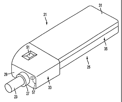
Referring to FIGS. 1 and 2, a preferred embodiment of the present invention
provides a smoking system 21 which preferably includes a partially-filled,
filter
cigarette 23 and a reusable lighter 25. The cigarette 23 is adapted to be
inserted into
and removed from a cigarette receiver 27 which is open at a front end portion
29 of
the lighter 25. Once the cigarette 23 is inserted, the smoking system 21 is
used in
much the same fashion as a more traditional cigarette, but without lighting or
smoldering of the cigarette 23. The cigarette 23 is discarded after one or
more puff
cycles.
Preferably, each cigarette 23 provides a total of eight puffs (puff cycles) or
CA 02475872 2004-08-16
WO 03/070031 PCT/US03/04235
-4-
more per smoke; however it is a matter of design expedient to adjust to a
lesser or
greater total number of available puffs. In the preferred embodiment, the
cigarette
23 includes at least one peripheral ring of perforations 12 located adjacent
the free
end 15 of the cigarette 23 and optionally a second ring or rings of
perforations 14
and optionally a plurality of holes 16 underneath the outer wrapper of the
cigarette
23.
The lighter 25 includes a housing 31 having front and rear housing portions
33 and 35. One or more batteries 35a are removably located within the rear
housing
portion 35 and supply energy to a heater fixture 39 which includes a plurality
of
electrically resistive, heating elements 37 (shown in FIGS. 3A-C). The heating
elements 37 are arranged within the front housing portion 33 to slidingly
receive the
cigarette 23 along an intermediate portion of the cigarette receiver 27. A
stop 183
located at the base 300 of the heater fixture 39 defines a terminus of the
cigarette
receiver 27.
A controller includes a control circuit 41 in the front housing portion 33
which selectively establishes electrical communication between the batteries
35a and
one or more the heater elements 37 during execution of each puff cycle. The
preferred embodiment of the present invention includes details concerning an
air
management system for effecting the admission and routing of air within the
lighter,
including aspects which are discussed in greater detail beginning with
reference to
FIG. 3C.
Still referring to FIGS. 1 and 2, preferably the rear portion 35 of the
lighter
housing 31 is adapted to be readily opened and closed, such as with screws or
snap-
fit components, so as to facilitate replacement of the batteries. If desired,
an
electrical socket or contacts may be provided for recharging the batteries in
a charger
supplied with house current or the like. Preferably, the front housing portion
33 is
removably joined to the rear housing portion 35, such as with a dovetail joint
or a
socket fit.
The batteries 35a are sized to provide sufficient power for the heaters 37 to
CA 02475872 2010-09-28
WO 03/070031 PCTIUS03104235
-5-
function as intended and preferably comprise a replaceable and rechargeable
type.
Alternate sources of power are suitable, such as capacitors. in the preferred
embodiment, the power source comprises four nickel-cadmium battery cells
connected in series with a total, non-loaded voltage in the range of
approximately
4.8 to 5.6 volts. The characteristics of the power source are, however,
selected in
view of the characteristics of other components in the smoking system 21,
particularly the characteristics of the heating elements 37. Commonly assigned
U.S.
Patent No. 5,144,962 describes several types of
power sources useful in connection with the smoking system of the present
invention, such as rechargeable battery sources and power arrangements which
comprise a battery and a capacitor which is recharged by the battery.
Referring specifically to FIG.: 2, preferably, the circuitry 41 is activated
by a
puff-actuated sensor 45 that is sensitive to either changes in pressure or
changes in
rate of air flow that occur upon initiation of a draw on the cigarette 23 by a
smoker.
The puff-actuated sensor 45 is preferably located within the front housing
portion 33
of the lighter 25 and is communicated with a space inside the heater fixture
39
adjacent the cigarette 23 via a port 45a extending through a side wall portion
182 of
the heater fixture 39. A puff-actuated sensor 45 suitable for use in the
smoking
system 21 is described in commonly assigned U.S. Patent No. 5,060,671 and U.S.
Patent No. 5,388,594.
The puff sensor 45 preferably comprises Fujikura Ltd. Model FSS-02 PG. Another
suitable sensor is a Model163PCO1D35 silicon sensor, manufactured by the
MicroSwitch division of Honeywell, Inc., Freeport, .Illinois. Flow sensing
devices,
such as those using hot-wire anemometry principles, have also been
successfully
demonstrated to be useful for actuating an appropriate one of the heater
elements 37
upon detection of a change in air flow. Once actuated by the sensor 45, the
control
circuitry 41 directs electric current to an appropriate one of the heater
elements 37.
An indicator 51 is provided at a location along the exterior of the lighter
25,
preferably on the front housing portion 33, to indicate the number of puffs
remaining
CA 02475872 2010-09-28
WO 03/070031 PCT/US03/04235
-6-
in a smoke of a cigarette 23. -The indicator 51 preferably includes a seven-
segment
liquid crystal display. In the preferred embodiment, the indicator 51 displays
a
segmented image which correlates with the digit "8" when a cigarette detector
57
detects the.ptesence of a.cigarette in-the heater fixture 39. The detector 57
preferably comprises an inductive coil 1102 adjacent-.the cigarette receiver
27 of the
heater fixture 39 and electric leads 1104 that communicate the coil 1.102 with
an
oscillator circuit within the control circuitry 41. The cigarette 23
internallybears a
foil ring or the like which can affect inductance of the coil winding 1102
such that
whenever a cigarette 23 is inserted into the receiver 27, the detector 57
generates a
signal to the circuitry 41 -indicative of the cigarette being present. The
control
circuitry 41 in turn provides a signal to the'indicator 51. The display of the
digit "8"
on the indicator 51 reflects that the eight puffs provided on each cigarette
23 are
available, i.e., no puff cycle has been undertaken and none of the heater
elements 37
have been activated to heat the cigarette 23. After the cigarette 23 is fully
smoked,
the indicator displays the digit "0". When the cigarette 23 is removed from
the
lighter 25, the cigarette detector 57 no longer detects a presence of a
cigarette 23 and
the indicator 51 is turned off.
The operation and details of the inductive cigarette detector 57 is provided
in
commonly assigned U.S. Patent No. 5,902,501. Other detectors may be employed
instead of the above-described one for the detector 57, such as a Type OPR5005
Light Sensor, manufactured by OPTEX Technology, Inc., 1215 West Crosby Road,
Carrollton, Texas 75006.
In the alternative to displaying the remainder of the puff count, the detector
display may instead be arranged to indicate whether the system is active or
inactive
("on" or "off").
As one of several possible alternatives to using the above-noted cigarette
detector 57, a mechanical switch'(not shown) may be provided to detect the
presence
or absence of a cigarette 23 and a reset button (not shown) may be provided
for
CA 02475872 2010-09-28
WO 03/070031 PCT/US03/04235
-7-
resetting the circuitry. 41 when a new cigarette is inserted into the lighter
25, e.g., to
cause the indicator 51 to display the-digit "8", etc. Power sources;
circuitry, puff-
actuated sensors, and indicators useful with the smoking system 21 of the
present
invention are described in commonly assigned, U.S. Patent Nos. 5,060,671;
5,388,594 and 5,591,368.
Referring now to FIGS. 3A and 3B, the front housing portion 33 of the
lighter 25 encloses a substantially cylindrical heater fixture 39 whose heater
elements 37 slidingly receive,the cigarette 23. The heater fixture 39 is
adapted to
support an inserted cigarette 23 in a fixed relation, to the heater elements
37 such that
the heater elements 37 are positioned alongside the cigarette 23 at
approximately the
same location along each newly inserted cigarette 23. In the preferred
embodiment,
the heater fixture 39 includes eight mutually parallel heater elements 37
which are
disposed concentrically about the axis of symmetry of the cigarette receiver
27. The
locations where each heater element 37 bears against (or is in thermal
communication with) a fully inserted cigarette 23 is referred to herein as the
heater
footprint or char zone 42. In the preferred embodiment, the char zone may
extend
approximately 14 mm in length, beginning approximately 9 mm from the free-end
15 of the cigarette 23. Of course, these relations may be varied amongst
different
lighter and cigarette designs. In another model for example, the char zone 42
extends from 12 mm to 23 mm from the free-end of the cigarette 23.
Referring also to FIG. 3C, to assure consistent placement of the heating
elements 37 relative to each cigarette 23 from cigarette to cigarette, the
heater fixture
39 is provided with a base portion 300 having a cupped stop-piece 183 against
which the free end 15 of the cigarette 23 is urged during its insertion into
the
cigarette receiver 27 of the lighter 25. The cupped shape of the stop-piece
183 is
configured to close-off (occlude) the free end 15 of the cigarette 23 upon
full
insertion of the cigarette 23 so that air cannot be drawn through the free end
15, but
instead only from along the side walls of the cigarette 23.
Still referring to FIGS. 3A and 3B, most preferably the heater elements 37
CA 02475872 2010-09-28
WO 03/070031 PCT/US03/04235
-8-
are of a design referred to herein as a wavy hairpin heater element 37,
wherein each
heater element 37 includes at least first and second serpentine, elongate
members
53a and 53b which are adjoined at an end portion (tip) 54. The tips 54 are
adjacent
the opening 55 of the cigarette receiver-27. The opposite-ends 56a and 56b of
each
heater element 37 are electrically connected to the'oppo'site poles of the
power
source 35a as selectively established by the controller 41. More specifically,
an
electrical pathway through each heater fixture 37 is established,
respectively,
through a terminal pin 104, a connection 121 between the pin 104 and a free
end
portion 56a ofone of the serpentine members 53a, through at least W portion of
the
tip 54 to the other serpentine member 53b and its end portion 56b: Preferably,
an
integrally formed, common connection ring 110 provides a common electrical
connection amongst all the end portions 56b' of the elongate member 53b. In
the
preferred embodiment, the ring 110 is connected to the positive terminal of
the
power source 35a (or common) through a connection 123 between the ring 110 and
a
pin 105. Further details of the construction and establishment of electrical
connections in the heater fixture 39 are illustrated and described in the
commonly
assigned U.S. Patent Nos. 5,060,671; 5,388,594 and 5,591,368. The heater
portions
53a, 53b and 54 establish what is here referred to as a heater blade 120.
Other preferred designs of the heater fixture 39 include heater elements in
the
form of a straight hairpin heater 'elements 37, which are set forth in the
commonly
assigned U.S. Patent No. 5,591,368 and "singular serpentine" heater elements
each
which are set forth in commonly assigned U.S. Patent No. 5,388,594.
Additional heater fixtures 37 that are operable as part of the lighter 25
include those disclosed in commonly assigned, U. S. Patent No. 5,665,262; and
commonly assigned, U.S. Patent go. 5.,498,855.
Preferably, the heaters 37 are individually energized by the power source 35a
CA 02475872 2010-09-28
WO 03/070031 PCT/US03/04235
-9-
under the control of the circuitry 41 to heat the cigarette 23 preferably
eight times at
spaced locations about the periphery of the cigarette 23. The heating renders
eight
puffs from the cigarette 23, as is commonly achieved with the smoking of a
more
traditional cigarette. It may be preferred to activate more than one heater
simultaneously for one. or more or all of the puffs.
Referring now to FIG. 4, the cigarette 23 is preferably constructed in
accordance with the preferred embodiment set forth in commonly assigned, U.S.
Patent No. 5,499,636.
Referring particularly to FIG. 3A, 3B, and 3C, preferably the puff sensor 45
is communicated to the interior of the heater fixture 39 through a port 45a. .
Preferably, the port 45a is located adjacent the base portion 300 of the
heater fixture
39. Such location minimizes the risk that-the port 45a and adjacent
passageways
leading thereto through the body of the.heater fixture 39 would become clogged
by
the debris or smoke condensates.
The heater fixture 39 includes an air inlet port 1200, which communicates
with a manifold 1202 that is at least partially defined by a perforated
annulus 1204
and the body of the receiver 27. The annulus 1204 includes preferably four
holes
1206 of approximately 0.029 inch diameter for effecting a minimal pressure
drop as
air is drawn into the lighter through the air inlet port 1200 and the manifold
1202.
The size and number of the holes 1206 may be varied, but such are configured
to
provide sufficient pressure drop that upon drawing action upon an inserted
cigarette
23, a pressure drop is induced upon the air entering the lighter such that the
puff
sensor 45 is operative to recognize initiation of a puff. In the preferred.
embodiment,
the holes 1206 of the annulus 1204 induce an RTD of approximately 25 mm water
plus or minus 5 mm. The range of pressure drop induced at the_ annulus 1204
should
be selected such that it is within the range of pressure drop detectable by
the
pressure sensor 45, but minimized to that need so that the remainder of
desired RTD
(Resistance To Draw) is effected predominantly by the cigarette 23. In the
preferred
embodiment, a grand total RTI) of 4 to 5 inches water (100 to 130 mm water) is
CA 02475872 2004-08-16
WO 03/070031 PCT/US03/04235
-10-
desired and approximately 25 mm of that is produced at the annulus 1204.
Accordingly, the RTD of the cigarette 23 is preferably in the range of
approximately
75 to 105 mm water RTD, when inserted in lighter 25 and the induced pressure
drop
of the lighter 25 is approximately 25 mm water. Adjustment of cigarette RTD in
accordance with the present invention includes provision of and adjustment of
the
number and extent of perforations 12 (and optionally 14) in the filled portion
88 of
the cigarette 23.
Advantageously, the holes 1206 of the annulus 1204, being located adjacent
the receiver 27, is positioned away from sources of debris and condensates
which
might otherwise tend to clog the holes 1206.
Air that has been drawn into the lighter upon initiation of a puff enters
alongside the cigarette with a substantial longitudinal (axial) velocity
component
toward the base portion 300 of the heater fixture 300. It has been discovered
that a
flow deflector or annular air-swoop 1210 adjacent the base portion 300
enhanced
smoke output (delivery) of the system 21 by directing at least a portion of
the
entering airflow back toward the inserted cigarette 23. Not wishing to be
bound by
theory, it is believed that the air-swoop 1210 tends to direct airflow toward
regions
of the cigarette 23 bearing perforations 12. Preferably, the annular air-swoop
1210
is located relative to a fully inserted cigarette 23 such that the air-swoop
1210
circumscribes the general location along the cigarette 23 of the perforations
12.
It has been discovered that the functioning of the air-swoop 1210 is
improved if it is constructed from metal, or alternatively, all body portions
of the
heater fixture 39 are constructed from a metal such as a stainless steel, or
at least
those portions of the heater fixture 39 that are disposed adjacent an inserted
cigarette
23. Such provision can provide an increase of delivery of 1 mg TPM (FTC).
The cigarette 23 comprises a tobacco rod 60 and a filter tipping 62, which are
joined together with tipping paper 64. The tobacco rod 60 of the cigarette 23
preferably includes a tobacco web or "mat" 66 which has been folded into a
tubular
(cylindrical) form about a free-flow filter 74 at one of its ends and a
tobacco plug 80
CA 02475872 2004-08-16
WO 03/070031 PCT/US03/04235
-11-
at the other. In the alternative, a plug of cellulose acetate might be used in
place of
the tobacco plug 80. The longitudinal (axial) extent of the tobacco plug 80
defines a
tobacco filled portion 88 of the partially-filled cigarette 23.
An overwrap 71 is intimately enwrapped about the tobacco web 66 and is
held together along a longitudinal seam as is common in construction of more
traditional cigarettes. The overwrap 71 retains the tobacco web 66 in a
wrapped
condition about a free-flow filter 74 and a tobacco plug 80.
The tobacco web 66 itself preferably comprises a base web 68 and a layer of
tobacco material 70 located along the inside surface of the base web 68. At
the
tipped end of the tobacco rod 60, the tobacco web 66 together with the
overwrap 71
are wrapped about the tubular free-flow filter plug 74. Preferably, the
tobacco plug
80 is constructed separately from the tobacco web 66 and comprises a
relatively
short column of cut filler tobacco that preferably has been wrapped within and
retained by a plug wrap 84.
As a general matter, the length of the tobacco plug 80 is preferably set
relative to the total length of the tobacco rod 60 such that a void 90 is
established
along the tobacco rod 60 between the free-flow filter 74 and the tobacco plug
80.
The void 90 corresponds to an unfilled portion of the tobacco rod 60 and is in
immediate fluid communication with the tipping 62 through the free flow filter
74 of
the tobacco rod 60.
The tipping 62 preferably comprises a free-flow filter 92 located adjacent the
tobacco rod 60 and a mouthpiece filter plug 94 at the distal end of the
tipping 62
from the tobacco rod 60. Preferably, the free-flow filter 92 is tubular and
transmits
air with very little pressure drop. Other low efficiency filters of standard
configuration could be used instead, however. The inside diameter for the free
flow
filter 92 is preferably at or between 2 to 6 mm and is preferably greater than
that of
the free flow filter 74 of the tobacco rod 60.
The mouthpiece filter plug 94 closes off the free end of the tipping 62 for
purposes of appearance and, if desired, to effect some filtration, although it
is
CA 02475872 2004-08-16
WO 03/070031 PCT/US03/04235
-12-
preferred that the mouthpiece filter plug 94 comprise a low efficiency filter
of
preferably about 15 to 25 percent efficiency.
Still referring to FIG. 4, preferably, the partially-filled cigarette 23
includes
at least one row of perforations 12 at a location adjacent the free end 15 of
the
tobacco rod portion of the cigarette 23. Preferably, the row of perforations
12 are
twelve holes in count and may be formed as slits 17 (perf-holes) at a 400
microsecond pulse width setting of a Hauni Model 500-1 on-line laser
perforator
system. Each perf-hole 17 of the row of perforations 12 preferably extends
through
the outer wrapper 71, through the tobacco mat 66 and the plug wrap 84.
Referring now also FIG. 2, preferably, the row of perforations 12 is located
at or adjacent to end portion 42a of the char zone 42. Such placement is
believed to
promote entrance of heated air into the tobacco plug 80 and create other
additional
favorable effects upon pyrolysis during a puff cycle such that delivery (TPM-
FTC)
is enhanced.
To further improve delivery, additional row or rows of perforations 14
comprising perf holes 17 as previously described may be provided at a location
along the filled portion 88 of the tobacco rod 60 preferably, at a location
superposed,
or at least partially superposed, by the heater char zone or footprint 42
and/or
alternatively, adjacent the free end 15 of the cigarette 23. In the latter
alternate
embodiment, the second row of perforations 14 is established at approximately
4
mm from the free end 15 of the cigarette 23. Either or both of the perforation
rows
12 or 14 may comprise a single row or a dual row of perf-holes 17.
The number and extent of perf-holes 17 are resolved in accordance with two
countervailing considerations. The addition of rows of perforation 12, 14 as
described above contributes to enhanced delivery of the cigarette 23. However,
each
additional row of perforations 12, 14 reduces RTD along the side walls of the
cigarettes 23. Preferably, the grand total RTD of the electrical smoking
system 21
should provide the smoker a resistance to draw approximately the same as that
experience with traditional cigarettes of approximately 4 to 5 inches water
CA 02475872 2010-09-28
WO 03/070031 PCT/US03/04235
-13-
(approximately 100-130 nun water) or thereabouts, 80-130 mm water.
It has been found that at a total energy input of 23.8 Joules to a heater
element 37, a cigarette 23 bearing a dual row of perforations 12 at a location
12 mm
from the free end 15 of the cigarette (dual rows of 12 holes each) can produce
deliveries substantially greater than 3 milligrams TPM (FTC). Further
deliveries
may be obtained by addition of a second row or rows of perforations 14.
However, each additional row of perf-holes 17 lowers RTD, which
preferably is to remain at or above 100 nun water for the whole system 21.
Should
one find that for a given cigarette 23, additional delivery is desired yet the
RTD
level is nearing its lower limit, additional delivery can be obtained by
provision of a
plurality of circumferentially spaced-apart holes 16 placed in the mat 6.6
itself.
Preferably, the mat holes 16 are each approximately one mm in diameter and
preferably 6 in number so that the requisite tensile strength of the mat
material 66 is
maintained and may withstand machine manufacturing. The mat holes can be
formed with apparatus as is described in commonly assigned U.S. Patent No.
5,666,976.
Preferably, the holes 16 in the mat 66 are covered by the outer wrapper 71.
Preferably, any row of perforations 12, 14 is displaced away from the location
of the
row of mat holes 16 so that they do not overlap. In a preferred embodiment,
the mat
holes 16 are located approximately 7 mm- from the free-end 15 of the cigarette
23,
and a dual row of perforations 12 is established approximately 12 mm from the
end
15 of the cigarette 23. So arranged, the cigarette achieves a 6 mg TPM (FTC)
or
more. Advantageously, the mat holes 16 can contribute an additional delivery
to the
cigarette 23 without the same extent of reduction in RTD as is experienced
with
each addition of row of perf-holes 17. Accordingly, one may utilize the rows
of
perforations 12, 14 to approximate desired delivery levels for the cigarette
23, with
the mat holes 16 being used to adjust or increase delivery with a lesser
effect on
RTD.
More traditional cigarettes exhibit a resistance to draw (RTD) of
CA 02475872 2010-09-28
WO 03/070031 PCT/US03/04235
-14-
approximately 80 mm to 130 mm water. The lighter of the electrical smoking
system according to the present invention when tested without a cigarette
exhibits an
RTD of approximately 20-30 mm water. The cigarettes according to the present
invention having the laser perforations-and mat'holes as taught herein exhibit
an
RTD of approximately 20-30 mm water when drawn upon by themselves (outside of
the lighter of the electrical smoking system), but when inserted, the-
electrical
smoking system (the lighter and the fully inserted cigarette) generate..an RTD
of
approximately 50-75 mm water.
Referring now to FIGS. 2 and 5, the electrical control circuitry 41 of the
lighter 25 includes a logic circuit 195, which preferably comprises a micro- .
controller or an application specific, integrated circuit (or "ASIC"). The
control
circuitry also includes the cigarette sensor 57 for detecting the insertion of
a
cigarette 23 in the cigarette receiver 27 of the lighter 25, the puff sensor
45 for
detecting a draw upon the inserted cigarette 23, the LCD indicator 5.1 for
indicating
the number of puffs remaining on a cigarette, the power source 35a and a
timing
network 197.
The logic circuit 195 may comprise any conventional circuit capable of
implementing the functions discussed herein. A field programmable gate array
(e.g., a type ACTEL A1280A FPGA PQFP 160, available from Actel Corporation,
Sunnyvale, California) or a micro controller can be programmed to perform the
digital logic functions with analog functions performed by other components.
An
ASIC or micro-controller can perform both the analog and digital functions in
one
component. Features' of control circuitry and logic circuitry similar to the
control
circuit 41 and logic circuit 195 of the present invention are disclosed, for
example,
in commonly assigned, U.S. Patent Nos. 5,388,594; 5,505,214; 5,591,368; and
5,499,636. Further details are also provided in commonly assigned U.S. Patent
No.
6,040;560.
In the preferred embodiment, eight individual heater elements 37 are
CA 02475872 2004-08-16
WO 03/070031 PCT/US03/04235
-15-
connected to a positive terminal of the power source 35a and to ground through
corresponding field effect transistor (FET) heater switches 201-208.
Individual (or
selected) ones of the heater switches 201-208 will turn on under control of
the logic
circuit 195 through terminals 211-218, respectively, during execution of a
power
cycle by the logic circuit 195. The logic circuit 195 provides signals for
activating
and deactivating particular ones of the heater switches 201-208 to activate
and
deactivate the corresponding heater element 37 of the heater fixture 39.
The logic circuit 195 cooperates with the timing circuit 197 to precisely
execute the activation and deactivation of each heater element 37 in
accordance with
a predetermined total cycle period ("Ttotat") and to precisely divide each
total cycle
period into a predetermined number of phases, with each phase having its own
predetermined period of time ("tphase") In the preferred embodiment, the total
cycle
period Ttotat has been selected to be 1.6 seconds (so as to be less than the
two-second
duration normally associated with a smoker's draw upon a cigarette, plus
provision
for margin) and the total cycle period Ttotat is divided preferably into two
phases, a
first phase having a predetermined time period ("tphase I") of 1.0 seconds and
a second
phase having a predetermined time period ("tphase 2") of 0.6 seconds. The
total cycle
period Ttotat, the total number of phases and the respective phase periods are
parameters, among others, that are resolved in accordance with the teachings
which
follow for establishing within the control circuit 41, a capacity to execute a
power
cycle that precisely duplicates a preferred thermal interaction ("thermal
profile" or
"thermo-histogram") between the respective heater element 37 and adjacent
portions
of the cigarette 23. Additionally, once the preferred thermo-histogram is
established, certain parameters (preferably, duty cycles within each phase)
are
adjusted dynamically by the control circuit 41 so as to precisely duplicate
the
predetermined thermo-histogram with every power cycle throughout the range of
voltages vin encompassed by the aforementioned battery discharge cycle.
The puff-actuated sensor 45 supplies a signal to the logic circuit 195 that is
indicative of smoker activation (i.e., a continuous drop in pressure or air
flow over a
CA 02475872 2004-08-16
WO 03/070031 PCT/US03/04235
-16-
sufficiently sustained period of time). The logic circuit 195 includes a
debouncing
routine for distinguishing between minor air pressure variations and more
sustained
draws on the cigarette to avoid inadvertent activation of heater elements in
response
to errant signal from the puff-actuated sensor 45. The puff-actuated sensor 45
may
include a piezoresistive pressure sensor or an optical flap sensor that is
used to drive
an operational amplifier, the output of which is in turn used to supply a
logic signal
to the logic circuit 195. Puff-actuated sensors suitable for use in connection
with the
smoking system include a Model 163PC01D35 silicon sensor, manufactured by the
MicroSwitch division of Honeywell, Inc., Freeport, Ill., or a type NPH-5-02.5G
NOVA sensor, available from Lucas-Nova, Fremont, California, or a type SLP004D
sensor, available from SenSym Incorporated, Sunnyvale, California.
The cigarette sensor 57 is located at the cigarette receiver 27 and supplies a
signal to the logic circuit 195 that is indicative of insertion of a cigarette
23 in the
lighter 25. Optionally a second sensor may be located adjacent the stop 183 so
as to
determine whether the cigarette has been fully inserted into the receiver 27.
In order to conserve energy, it is preferred that the puff-actuated sensor 45
and the cigarette sensor 57 be cycled on and off at low duty cycles (e.g.,
from about
a 2 to 10% duty cycle). For example, it is preferred that the puff actuated
sensor 45
be turned on for a 1 millisecond duration every 10 milliseconds. If, for
example, the
puff actuated sensor 45 detects pressure drop or air flow indicative of a draw
on a
cigarette during four consecutive pulses (i.e., over a 40 millisecond period),
the puff
actuated sensor sends a signal through a terminal 221 to the logic circuit
195. The
logic circuit 195 then sends a signal through an appropriate one of the
terminals 211-
218 to turn an appropriate one of the FET heater switches 201-208 ON.
Similarly, the cigarette sensor 57 is preferably turned on for a 1 millisecond
duration every 10 milliseconds. If, for example, the cigarette sensor 57
detects four
consecutive reflected pulses, indicating the presence of a cigarette 23 in the
lighter
25, the light sensor sends a signal through terminal 223 to the logic circuit
195. The
logic circuit 195 then sends a signal through terminal 225 to the puff-
actuated sensor
CA 02475872 2004-08-16
WO 03/070031 PCT/US03/04235
-17-
45 to turn on the puff-actuated sensor. The logic circuit 195 also sends a
signal
through terminal 227 to the indicator 51 to turn it on. The above-noted
modulation
techniques reduce the time average current required by the puff actuated
sensor 45
and the cigarette sensor 57, and thus extend the life of the power source 37.
The logic circuit 195 includes a PROM (programmable read-only memory)
301, which includes preferably at least two data bases or "look-up tables" 302
and
304, and optionally, a third data base (look-up table) 306 and possibly a
fourth look-
up table 307. Each of the look-up tables 302, 304 (and optionally 306, 307)
converts
a signal indicative of battery voltage v1 to a signal indicative of the duty
cycle
("dc1" for the first phase and "dc2" for the second phase) to be used in
execution of
the respective phase of the immediate power cycle. Third and fourth look-up
tables
306 and 307 function similarly.
Upon initiation of a power cycle, the logic circuit receives a signal
indicative
of battery voltage v;,,, and then references the immediate reading v,,, to the
first look-
up table 302 to establish a duty cycle dc1 for the initiation of the first
phase of the
power cycle. The first phase is continued until the timing network 197
provides a
signal indicating that the predetermined time period of the first phase
(tphase 1) has
elapsed, whereupon the logic circuit 195 references v;,, and the second look-
up table
304 and establishes a duty cycle dc2 for the initiation the second phase. The
second
phase is continued until the timing network 197 provides a signal indicating
that the
predetermined time period of the second phase (tphase 2) has elapsed,
whereupon the
timing network 197 provides a shut-off signal to the logic circuit 195 at the
terminal
229. Optionally, the logic circuit 195 could initiate a third phase and
establish a
third duty cycle dc3, and the shut-off signal would not be generated until the
predetermined period of the third phase (tphase 3) had elapsed. A similar
regimen
could optionally be established with a fourth phase (tphase4). The present
invention
could be practiced with additional phases as well.
Although the present invention can be practiced by limiting reference to the
look-up tables to an initial portion of each phase to establish a duty cycle
to be
CA 02475872 2010-09-28
WO 03/076031 PCT/US03/04235
-18-
applied throughout the substantial entirety of each phase. 'a refinement and
the
preferred practice is to have the logic circuit 195 configured to continuously
reference vi,, together with the respective look-up tables 302; 303, 306 and
307 so as
to dyaamicaily adjust the values set for duty cycles in response to
fluctuations in
battery voltage as the control circuit progresses through each phase. Such
device
provides a more precise repetition of the desired thermo-histogram.
Other timing network circuit configurations and logic circuits may also be
used, such as those described in the commonly assigned, U.S. Patent Nos.
5,388,59.1; 5,505,214; 5,591,368; 5,499,636; and 5,372,148.
.
During oleratiioil, a cigarette 23 is inserted in the lighter 25 and the
presence
of the cigarette is detected by the cigarette sensor 57. The cigarette sensor
57 sends
a signal to the logic circuit 195 through terminal 223. The logic circuit 195
ascertains whether the power source 35a is charged or whether the immediate
voltage is below an acceptable minimum v;,, min- If, after insertion of a
cigarette 23 in
the lighter 25, the logic circuit 195 detects that the voltage of the power
source 35a
is too low, below Vin in, the indicator 51 blinks and further operation of the
lighter
will be blocked until the power source 35a is recharged or replaced. Voltage
of the
power source 35a is also monitored during firing of the heater elements 37 and
the
firing of the heater elements 311 is interrupted if the voltage drops below a
predetermined value.
If the power source 35a is charged and voltage is sufficient, the logic
circuit
195 sends a signal through terminal 225 to the puff sensor 45 to determine
whether a
smoker is drawing on the cigarette 23. At the same time, the logic circuit 195
sends
a signal through the terminal 227 to the indicator 51 so that the LCD will
display the
digit "8", reflecting that eight puffs are available.
When the logic circuit 195 receives a signal through terminal 221 from the
puff-actuated" sensor 45 that a sustained pressure drop or air flow has-been
detected,
the logic circuit 195 sends a signal through terminal 231 to the tuner network
197 to
CA 02475872 2010-09-28
WO 03/070031 PCT/US03/04235
-19-
activate the timer network, which then,begins to function phase by phase in
the
manner previously described. The logic circuit 195. also determines, by a
downcount routine, which one of the eight heater elements is due to be heated
and
sends a signal through an-appropriate -terminal 211-218 to turn an appropriate
one of
the = i,
FET heater switches 201-208 ON..;The: appropriate heater stays on while the
timer
runs.
When-the timing network 197 sends a signal through terminal 229 to the
logic circuit 195 indicating that the. timer has stopped running, the
particular ON
FET heater switch 211-218 is turned OFF, thereby removing power from the
particular heater element 37. The logic circuit, 195 also downcounts and sends
a
signal to the indicator 51 through terminal 227 so: that the indicator will
display that
one less puff is remaining (e,g., "7", after the first puff). When the smoker
next
puffs on the cigarette 23, the logic circuit 195 will turn ON another
predetermined
one of the FET heater switches 211-218, thereby supplying power to another
predetermined one of the heater elements. The process will be repeated until
the
indicator 51 displays "0", meaning that there are no more puffs remaining on
the
cigarette 23. When the cigarette 23 is removed from the lighter 25, the
cigarette
sensor 57 indicates that a cigarette is not present, apd the logic circuit 195
is reset.
Other features, such as those described in U.S. Patent No. 5,505,214;
5,388,594; and 5,372,148 maybe incorporated
in the control circuitry 41 instead of or in addition,to the features
described above.
For example, if desired, various disabling features may be provided. One type
of
disabling feature includes timing circuitry (not shown) to prevent successive
puffs
from occurring too close together, so that the power source 35a has time to
recover.
Another disabling feature includes means for disabling the heater elements 37
if an
unauthorized product is inserted in the heater fixture 39.. For example, the
cigarette
23 might be provided with an identifying characteristic that the lighter 25
must
recognize before the heating elements 37 are energized.
CA 02475872 2004-08-16
WO 03/070031 PCT/US03/04235
-20-
Referring now to FIG. 6, the cigarette 23, as constructed in accordance with
the preferred embodiment of the present invention, comprises a tobacco rod 60
and a
filter tipping 62, which are joined together with tipping paper 64. During
manufacture of the cigarette, perforation holes 263 can be provided in one or
more
locations in the outer surface of the tobacco rod 60.
The partially-filled, filter cigarette 23 preferably has an essentially
constant
diameter along its length and, which like more traditional cigarettes, is
preferably
between approximately 7.5 mm and 8.5 mm in diameter so that the smoking system
21 provides a smoker a familiar "mouth feel". In the preferred embodiment, the
cigarette 23 is approximately 62 mm in overall length, thereby facilitating
the use of
conventional packaging machines in the packaging of the cigarettes 23. The
combined length of the mouthpiece filter 94 and the free-flow filter 92 is
preferably
30 mm. The tipping paper preferably extends approximately 6 mm over the
tobacco
rod 60. The total length of the tobacco rod 60 is preferably 32 mm. Other
proportions, lengths and diameters may be selected instead of those recited
above for
the preferred embodiment.
The tobacco rod 60 of the cigarette 23 preferably includes a tobacco web or
mat 66 which has been folded into a tubular (cylindrical) form.
An overwrap 71 intimately enwraps the tobacco web 66 and is held together
along a longitudinal seam as is common in construction of more traditional
cigarettes. The overwrap 71 retains the tobacco web 66 in a wrapped condition
about a free-flow filter 74 and a tobacco plug 80.
Preferably, the cigarette overwrap paper 71 is wrapped intimately about the
tobacco web 66 so as to render external appearance and feel of a more
traditional
cigarette. It has been found that a better tasting smoke is achieved when the
overwrap paper 71 is a standard type of cigarette paper, preferably a flax
paper of
approximately 20 to 50 CORESTA (defined as the amount of air, measured in
cubic
centimeters, that passes through one square centimeter of material, e.g., a
paper
sheet, in one minute at a pressure drop of 1.0 kilopascal) and more preferably
of
CA 02475872 2004-08-16
WO 03/070031 PCT/US03/04235
-21-
about 30 to 45 CORESTA, a basis weight of approximately 23 to 35 grams per
meter squared (g/m2) and more preferably about 23 to 30 g/m2, and a filler
loading
of approximately 23 to 35% by weight and more preferably 28 to 33% by weight.
The overwrap paper 71 preferably contains little or no citrate or other bum
modifiers, with preferred levels of citrate ranging from 0 to approximately
2.6% by
weight of the overwrap paper 71 and more preferably less than 1%.
The tobacco web 66 itself preferably comprises a base web 68 and a layer of
tobacco material 70 located along the inside surface of the base web 68. At
the
tipped end 72 of the tobacco rod 60, the tobacco web 66 together with the
overwrap
71 are wrapped about the tubular free-flow filter plug 74. The free-flow
filter 74
(also known in the art as "whistle-through" plugs) provides structural
definition and
support at the tipped end 72 of the tobacco rod 60 and permits aerosol to be
withdrawn from the interior of the tobacco rod 60 with a minimum pressure
drop.
The free-flow filter 74 also acts as a flow constriction at the tipped end 72
of the
tobacco rod 60, which is believed to help promote the formation of aerosol
during a
draw on the cigarette 23. The free-flow filter is preferably at least 7
millimeters long
to facilitate machine handling and is preferably annular, although other
shapes and
types of low efficiency filters are suitable, including cylindrical filter
plugs.
At the free end 78 of the tobacco rod 60, the tobacco web 66 together with
the overwrap 71 are wrapped about a cylindrical tobacco plug 80. Preferably,
the
tobacco plug 80 is constructed separately from the tobacco web 66 and
comprises a
relatively short column of cut filler tobacco that has been wrapped within and
retained by a plug wrap 84.
Preferably the tobacco plug 80 is constructed on a conventional cigarette rod
making machine wherein cut filler (preferably blended) is air formed into a
continuous rod of tobacco on a traveling belt and entrapped with a continuous
ribbon
of plug wrap 84 which is then glued along its longitudinal seam and heat
sealed. In
accordance with the preferred embodiment of the present invention, the plug
wrap
84 is preferably constructed from a cellulosic web of little or no filler,
sizing or burn
CA 02475872 2004-08-16
WO 03/070031 PCT/US03/04235
-22-
additives (each at levels below 0.5% weight percent) and preferably little or
no
sizing. Preferably, the tobacco plug wrap 84 has a low basis weight of below
15
grams per meter squared and more preferably about 13 grams per meter squared.
The tobacco plug wrap 84 preferably has a high permeability in the range of
about
20,000 to 35,000 CORESTA and more preferably in the range of about 25,000 to
35,000 CORESTA, and is constructed preferably from soft wood fiber pulp, abaca-
type cellulose or other long fibered pulp. Such papers are available from
Papierfabrik Schoeller and Hoescht GMBH, Postfach 1155, D-76584, Gernsback,
GERMANY; another paper suitable for use as the plug wrap 84 is the paper TW
2000 from DeMauduit of Euimperle FRANCE, with the addition of carboxy-methyl
cellulose at a 2.5 weight percent level.
The tobacco rod making machine is operated so as to provide a tobacco rod
density of approximately 0.17 to 0.30 grams per cubic centimeter (g/cc), but
more
preferably in a range of at least 0.20 to 0.30 g/cc and most preferably
between about
0.24 to 0.28 g/cc. The elevated densities are preferred for the avoidance of
loose
ends at the free end 78 of the tobacco rod 60. However, it is to be understood
that
the lower rod densities will allow the tobacco column 82 to contribute a
greater
proportion of aerosol and flavor to the smoke. Accordingly, a balance must be
struck between aerosol delivery (which favors a low rod density in the tobacco
column 82) and the avoidance of loose-ends (which favors the elevated ranges
of rod
densities).
The tobacco column 82 preferably comprises cut filler of a blend of tobaccos
typical of the industry, including blends comprising bright, burley and
oriental
tobaccos together with, optionally, reconstituted tobaccos and other blend
components, including traditional cigarette flavors. However, in the preferred
embodiment, the cut filler of the tobacco column 84 comprises a blend of
bright,
burly and oriental tobaccos at the ratio of approximately 45:30:25 for the
U.S.
market, without inclusion of reconstituted tobaccos or any after cut
flavorings.
Optionally, an expanded tobacco component might be included in the blend to
adjust
CA 02475872 2010-09-28
WO 03/070031 PCT/US03/04235
-23-
rod density, and flavors may be added.
The continuous tobacco rod formed as described above is sliced in
accordance with a predetermined plug length for the tobacco plug 80. This
length is
preferably at least 7 mm in order to facilitate machine handling. However, the
length may vary from about 7 mm to 25 mm or more depending on preferences in
cigarette design which will become apparent in the description which follows,
with
particular reference to FIG. 7.
As a general matter, the length of the tobacco plug 80 is preferably set
relative to the total length of the tobacco rod 60 such that a void 91 is
defined along
the tobacco rod 60 between the free-flow filter 74 and the tobacco plug 80.
The void
91 corresponds to an unfilled portion of the tobacco rod 60 and is in
immediate fluid
communication with the tipping 62 through the free flow filter 74 of the
tobacco rod
60.
Referring particularly to FIG. 6, the length of the tobacco plug 80 and its
relative position along the tobacco rod 60 is also selected in relation to
features of
the heater elements 37. When a cigarette is properly positioned against a stop
182
within the lighter 25, a portion 93 of each heater element 37 will contact the
tobacco
rod 60 along a region of the tobacco rod 60. This region of contact is
referred to as a
heater footprint 95. The heater footprint 95 (as shown with a double arrow in
FIG.
6) is not part of the cigarette structure itself, but instead is a
representation of that
region of the tobacco rod 60 where the heater element 37 would be expected to
reach
operative heating temperatures during smoking of the cigarette 23. Because the
heating elements 37 are a fixed distance 96 from the stop 182 of the heater
fixture,
the heater foot print 95 consistently locates along the tobacco rod 60 at the
same
predetermined distance 96 from the free end 78 of the tobacco rod 60 for every
cigarette 23 that is fully inserted into the lighter 25.
Preferably, the length of the tobacco plug 80, the length of the heater
footprint 95 and the distance between the heater footprint 95 and the stop 182
are
selected such that the heater footprint 95 extends beyond the tobacco plug 80
and
CA 02475872 2004-08-16
WO 03/070031 PCT/US03/04235
-24-
superposes a portion of the void 91 by a distance 98. The distance 98 by which
the
heater footprint 95 superposes the void 91 (the unfilled portion of the
tobacco rod
60) is also referred to as the "heater-void overlap" 98. The distance by which
the
remainder of the heater footprint 95 superposes the tobacco plug 80 is
referred to as
the "heater-filler overlap" 99.
The tipping 62 preferably comprises a free-flow filter 92 located adjacent the
tobacco rod 60 and a mouthpiece filter plug 94 at the distal end of the
tipping 62
from the tobacco rod 60. Preferably the free-flow filter 92 is tubular and
transmits
air with very little pressure drop. Other low efficiency filters of standard
configuration could be used instead, however. The inside diameter for the free
flow
filter 92 is preferably at or between 2 to 6 millimeters and is preferably
greater than
that of the free flow filter 74 of the tobacco rod 60.
The mouthpiece filter plug 94 closes off the free end of the tipping 62 for
purposes of appearance and, if desired, to effect some filtration, although it
is
preferred that the mouthpiece filter plug 94 comprise a low efficiency filter
of
preferably about 15 to 25 percent efficiency.
The free-flow filter 92 and the mouthpiece filter plug 94 are preferably
joined together as a combined plug with a plug wrap 101. The plug wrap 101 is
preferably a porous, low weight plug wrap as is conventionally available to
those in
the art of cigarette making. The combined plug is attached to the tobacco rod
60 by
the tipping paper 64 of specifications that are standard and conventionally
used
throughout the cigarette industry. The tipping paper 64 may be either cork,
white or
any other color as decorative preferences might suggest.
Preferably, a cigarette 23 constructed in accordance with the preferred
embodiment has an overall length of approximately 62 mm, of which 30 mm
comprises the combined plug of the tipping 62. Accordingly, the tobacco rod 60
is
32 mm long. Preferably, the free-flow filter 74 of the tobacco rod 60 is at
least 7
mm long and the void 91 between the free-flow filter 74 and the tobacco plug
80 is
preferably at least 7 mm long. In the preferred embodiment, the heater foot
print 95
CA 02475872 2004-08-16
WO 03/070031 PCT/US03/04235
-25-
is approximately 12 mm long and located such that it provides a 3 mm heater-
void
overlap 98, leaving 9 mm of the heater foot print 95 superposing the tobacco
plug
80.
It is to be understood that the length of the void 91, the length of the
tobacco
plug 80, and the distribution of the perforation holes 263 may be adjusted to
facilitate manufacturing and more importantly, to adjust the smoking
characteristics
of the cigarette 23, including adjustments in its taste, draw and delivery.
The pattern
of holes 263, the length of the void 91 and the amount of heater-filler
overlap (and
heater-void overlap) may also be manipulated to adjust the immediacy of
response,
to promote consistency in delivery (on a puff-to-puff basis as well as between
cigarettes) and to control condensation of aerosol at or about the heaters.
In the preferred embodiment, the void 91 (the filler-free portion of the
tobacco rod 60) extends approximately 7 mm to assure adequate clearance
between
the heater foot print 95 and the free-flow filter 74. In this way, margin is
provided
such that the heater foot print 95 does not heat the free-flow filter 74
during
smoking. Other lengths are suitable, for instance, if manufacturing tolerances
permit, the void 91 might be configured as short as approximately 4 mm or
less, or
in the other extreme, extended well beyond 7 mm so as establish an elongate
filler-
free portion along the tobacco rod 60. The preferred range of lengths for the
filler-
free portion (the void 91) is from approximately 4 mm to 18 mm and more
preferably 5 to 12 mm.
In another embodiment, a cigarette 23 has an overall length of approximately
68 mm, of which 36 mm comprises the combined plug of the tipping 62.
Accordingly, the tobacco rod 60 is 32 mm long. Preferably, the free-flow
filter 74
of the tobacco rod 60 is at least 13 mm long and the void 91 between the free-
flow
filter 74 and the tobacco plug 80 is preferably at least 7 mm long.
Regardless of the length of the cigarette, the cigarette can include filter
material, e.g., the void space can contain filter material such as activated
carbon,
flavored carbon, silica gel particles, or other filtering material. Also, the
controller
CA 02475872 2010-09-28
WO 03/070031 PCT/US03/04235
-26-
can be programmed to operate the heater fixture so as to warm.the cigarette
upon
insertion thereof into the EHCSS. For example, the control circuitry can be
operable
to cause delivery of energy to the heater blades (e.g., about 5-6 Joules) to
thereby
warm the cigarette such that moisture moves: from the wrapper into the central
portion of the cigarette.
During smoking-of the cigarette, the controller preferably activates one of
the
heating blades to'apply heat to a heating zone along the outer periphery of
the
cigarette. For example, the zone can range in size from 3 to 25 mm2 as
mentioned in
commonly assigned U.S. Patent No. 5,750,964. A
preferred heating zone for a cigarette having a wrapper with an ammonium
containing compound filler therein has a length of 10 to 20 mm and covers an
area
of 10 to 20 mm2 and the preferred amount-of heat applied to the heating blade
in
accordance with a programmed power cycle is 15 to 40 Joules, preferably 20 to
35
Joules. With such heating, the heating zone can be heated to a temperature of
up to
500 C and the tobacco mat can be heated to a temperature of about 200 to 350
C,
preferably 220 to 3200C. Due to resistance heating of the heater blade, the
temperature of the blade may be somewhat lower at each longitudinal end
thereof,
e.g., the temperature of the blade may be 25 to 50 C higher in the central
portion of
the blade when the blade reaches its maximum temperature.
It has been found that the controlled heating of the heated blade in
combination with use ofa cigarette wrapper having an ammonium containing
compound filler results in reduction in various constituents of the tobacco
smoke. A
preferred ammonium containing compoundfiller is ammonium magnesium
phosphate (AMP) and the.heater blade is preferably supplied 20 to 35 Joules of
energy according to the aforementioned programmed power cycle when activated
by
the controller. A preferred temperature of the tobacco mat along the heating
zone
during heating of a heater blade-is 200 to 400 C, more preferably 220 to 320
C.
Also, it is preferred that the cigarette include laser perforations and/or mat
holes as
discussed above. Moreover, it is preferred that the EHCSS occlude the free end
of
CA 02475872 2004-08-16
WO 03/070031 PCT/US03/04235
-27-
the cigarette to minimize flow of ambient air into the free end and include an
air
swoop to direct ambient air towards the laser perforations and/or mat holes as
discussed above.
According to the invention, the EHCSS is used to smoke a cigarette
wherein the cigarette wrapper includes an ammonium containing compound filler
such as magnesium ammonium phosphate (AMP), preferably the monohydrate
form of AMP in an amount effective to reduce the contents of a plurality of
gaseous components in the smoke produced by combustion/pyrolysis of the
cigarette. Compared to cigarette paper wherein calcium carbonate is the sole
filler, when the ammonium containing compound filler is used it.is possible to
reduce the amounts of gas constituents in the mainstream smoke of the smoking
system, such constituents including aldehydes (e.g., formaldehyde,
acetaldehyde,
propionaldehyde), carbon monoxide, 1,3-butadiene, isoprene, acrolein,
acrylonitrile, hydrogen cyanide, o-toluidine, 2-naphtylamine, nitrogen oxide,
benzene, NNN, phenol, catechol, benz(a)anthracene, benzo(a)pyrene, etc.
FIGS. 7-8 show results of relative measurements of tobacco smoke
constituents produced in an EHCSS using cigarettes with ammonium containing
compound filler (i.e., the monohydrate form of AMP) compared to CaCO3 filler.
As shown, the general levels of smoke constituents such as TPM, tar, and water
are substantially the same for both cigarettes whereas nicotine and acrolein
levels
are reduced somewhat and the remaining constituents are dramatically reduced
for
the ammonium containing compound filler. One constituent which was not
reduced in the tests was 2-nitropropane. Also, while not shown in FIGS. 7-8,
the
ammonia levels in the tobacco smoke are elevated for ammonium containing
compound filler.
When compared to a conventional light standard reference cigarette
(1R4F), the electrically heated cigarette according to the invention with
ammonium magnesium phosphate (AMP) incorporated into the paper wrapper
yields approximately 90% lower concentrations of carbon monoxide, 1,3-
CA 02475872 2004-08-16
WO 03/070031 PCT/US03/04235
-28-
butadiene, acrylonitrile, benzene, and benzo(a)pyrene on a per mg TPM basis
compared to the conventional light standard reference cigarette (1R4F).
Aldehydes were 40 % lower (one exception, formaldehyde, was 75 % higher).
The wrapper according to the invention can be manufactured by
conventional papermaking processes wherein a filler, of low solubility,
effective in
reducing the content of gaseous components in smoke is added either by itself
or
as a mixture with other filler materials to an aqueous slurry containing
cellulosic
material.
The monohydrate form of AMP (MgNH4PO4=xH20 wherein x is 1) has a
low solubility in water so as to be compatible with conventional papermaking
processes, e.g., the filler is substantially insoluble in an aqueous
dispersion
containing ingredients of the paper such as flax, etc. That is, the ammonium
containing compound filler is stable enough in a papermaking process to
survive
intact as filler in the final paper product. This includes sufficient thermal
stability
to survive the drying steps in the papermaking process. The ammonium
containing compound filler also evolves ammonia during the smoking process
while decreasing the content of gaseous constituents such as low molecular
weight
aldehydes in smoke. The monohydrate form of AMP (mono-AMP) is also known
as dittmarite and can be derived from raw ingredients or converted into the
mono-
form from the hexavalent form known as struvite. The mono-AMP can be
provided with a range of surface areas, a range of particle sizes (mostly in
the
micron range), possess appropriate opacity, have low solubility in water
(required
for papermaking), and possess other properties that are considered desirable
in
fillers for cigarette papers. For purposes of a filler for cigarette paper,
the mono-
AMP preferably has a particle size below 25 m, more preferably below 10 m.
When used as filler in the fabrication of wrappers for cigarettes of an
EHCSS, a preferred amount of the ammonium containing compound filler is equal
to about 10 % to about 60 % of the final wrapper weight, more preferably about
20% to about 50% by weight. This percentage is referred to as the filler
loading.
CA 02475872 2004-08-16
WO 03/070031 PCT/US03/04235
-29-
Although the ammonium containing compound filler is preferably the sole
filler, it
can be mixed with one or more other fillers in the paper. In the case of
mixtures,
a portion, e.g., up to 60% by weight, of the filler loading can comprise one
or
more inorganic carbonate, inorganic hydroxide, inorganic oxide, or inorganic
phosphate. Examples of such fillers include, e.g., calcium carbonate,
magnesium
hydroxide, magnesium oxide, magnesium carbonates, and titanium dioxide as well
as other fillers known in the art.
The wrappers containing the ammonium containing compound filler can
have a basis weight of between about 15 to about 75 grams per square meter and
can have a porosity of between about 2 to about 200 cubic centimeters per
minute
per square centimeter as measured by the CORESTA method ("CORESTA
units"). A preferred basis weight is between about 20 to about 50 grams per
square meter and the most preferred porosity is between about 10 to about 110
CORESTA units. A more preferred basis weight is between about 25 to about 30
grams per square meter and the most preferred porosity is between about 25 to
about 50 CORESTA units.
Burn additives such as alkali metal salts of carboxylic acids or phosphoric
acids can be applied to the wrapper to adjust or control the burn rate of the
resulting smoking article. For example, burn additives can be applied in
amounts
ranging from about 2 % to about 15 % by weight of the wrapper. Examples of
burn additives include sodium fumarate, sodium citrate, potassium citrate,
potassium succinate, potassium monohydrogen phosphate, and potassium
dihydrogen phosphate.
To prepare wrappers containing the ammonium containing compound filler,
conventional cigarette papermaking procedures can be used with the inclusion
of
an ammonium-containing compound filler in place of or in combination with a
conventional cigarette paper filler such as calcium carbonate. The paper
wrappers
may be made from flax, wood pulp, or other plant fibers. In addition, the
paper
wrappers may be a conventional one wrapper construction, a multiwrapped
CA 02475872 2004-08-16
WO 03/070031 PCT/US03/04235
-30-
construction or a multilayer single wrap construction.
If the ammonium containing compound filler comprises the monohydrate
form of magnesium ammonium phosphate, it can be incorporated in the cigarette
paper as follows. For instance, a slurry of the monohydrate form of magnesium
ammonium phosphate can be mixed with feedstock of a paper making machine or
the slurry can be dried to particle form (e.g., powder) and such powder can be
incorporated in the paper making feedstock. In order to prevent the magnesium
ammonium phosphate in the monohydrate form from transforming back to the
hexahydrate form, it is desirable to maintain the slurry above 55'C until it
is
incorporated directly in feedstock (preferably heated above 60'Q of the paper
making machine or until the slurry is dried into particle form such as by
flash
drying which removes the water from the slurry under elevated temperature
conditions. Once dry, the monohydrate form of the magnesium ammonium
phosphate remains stable. The magnesium ammonium phosphate preferably has a
particle size in the range of approximately 2,um to 81um, more preferably in
the
range of 2,um to 4,um.
It is to be understood that the present invention may be embodied in other
specific forms and process the use without departing from the spirit or
essential
characteristics of the present invention. Thus, while the invention has been
illustrated and described in accordance with various preferred embodiments, it
is
recognized that variations and changes may be made therein without departing
from
the invention as set forth in the claims.