Language selection

Search

Patent 2476092 Summary

Third-party information liability

Some of the information on this Web page has been provided by external sources. The Government of Canada is not responsible for the accuracy, reliability or currency of the information supplied by external sources. Users wishing to rely upon this information should consult directly with the source of the information. Content provided by external sources is not subject to official languages, privacy and accessibility requirements.

Claims and Abstract availability

Any discrepancies in the text and image of the Claims and Abstract are due to differing posting times. Text of the Claims and Abstract are posted:

  • At the time the application is open to public inspection;
  • At the time of issue of the patent (grant).
(12) Patent Application: (11) CA 2476092
(54) English Title: GROUND-ENGAGING APPARATUS FOR TRANSPORT TRAILER
(54) French Title: DISPOSITIF DE DISTRIBUTION DU POIDS POUR REMORQUE DE TRANSPORT
Status: Deemed Abandoned and Beyond the Period of Reinstatement - Pending Response to Notice of Disregarded Communication
Bibliographic Data
Abstracts

English Abstract


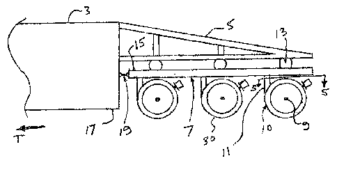
A vehicle apparatus comprises a frame with the axles attached to the frame
such that the
vertical distance between the axles and frame is constant, and the vehicle
body is attached
to the frame through a plurality of suspension units. The axles, attached
wheels, .and
frame thus move up and down together, and the movement of the frame is
essentially an
average of the movement up and down of all the axles supporting the frame.
Thus each
axle does not exert an independent force on the vehicle body, and variations
in forces
experienced by the vehicle body are reduced. Wheels can be distributed across
the width
of the vehicle apparatus thereby distributing a vehicle weight across the
width of the road
surface. Outside wheels can be mounted on axle arms that pivot about a
vertical axis,
such that they can be pivoted out of the way to allow access to inside wheels
for
maintenance.


Claims

Note: Claims are shown in the official language in which they were submitted.


8
CLAIMS:
What is claimed is:
1. A suspension apparatus for mounting ground engaging wheels to a vehicle,
the
assembly comprising:
an axle frame;
a plurality of axles attached under the axle frame such that a vertical
distance
between the axles and frame is substantially constant;
at least one wheel mounted on each axle and supporting the axle frame for
movement along the ground in an operating travel direction;
at least one suspension unit mounted on the axle frame;
frame couplers attached to the axle frame at a first portion thereof and
adapted at
a second portion thereof for attachment to the vehicle;
wherein the axle frame is attachable to a vehicle body such that a weight of
the
vehicle body is supgorted on the at least one suspension unit.
2. The apparatus of Claim 1 wherein the suspension units comprise at least one
of air
springs, leaf springs, and coil springs.
3. The apparatus of any one of Claims 1 and 2 wherein at least one frame
coupler is
pivotally attached to the axle frame about a substantially horizontal axis
oriented
substantially perpendicular to the operating travel direction and adapted for

9
pivotal attachment to the vehicle about a substantially horizontal axis
oriented
substantially perpendicular to the operating travel direction.
4. The apparatus of any one of Claims 1-3 wherein the frame coupler is
resilient
thereby changing shape in response to force.
5. The apparatus of any one of Claims 1-4 comprising an axle arm extending
upward from at least one axle and pivotally attached to the axle frame about a
substantially vertical axis.
6. The apparatus of Claim 5 further comprising an alignment rod attached to at
least
one axle arm and to the axle frame such that movement of the at least one axle
arm about the vertical axis is inhibited.
7. The apparatus of Claim 6 wherein the alignment rod is flexible such that
the at
least one axle arm can pivot about the vertical axis in response to force
applied
thereto.
8. The apparatus of any one of Claims 6 and 7 wherein a length of the
alignment rod
is adjustable.
9. The apparatus of any one of Claims 5 - 7 comprising right, center, and left
axle
arms extending upward from respective right, center, and left axles and
pivotally
attached to the axle frame about respective right, center, and left
substantially
vertical axes laterally spaced substantially evenly across the axle frame.
10. The apparatus of Claim 8 further comprising an alignment rod attached to
each
axle arm and to the axle frame such that movement of each axle arm about the
vertical axis is inhibited.

10
11. The apparatus of Claim 9 wherein alignment rods attached to the right and
left
axle arms are removable such that the right and left axle arms can pivot to
provide
access to the center axle.

Description

Note: Descriptions are shown in the official language in which they were submitted.


CA 02476092 2004-07-29
2
APPARATUS 1FOR MOUNTING W~ELS TO A VEHICLE BODY
This invention is in the field of vehicles and in particular the wheels
supporting such
vehicles.
BACKGROUND
Typical trucks, trailers, and like vehicles have a body fixed to a frame that
is supported
on one or more axles with attached wheels. Conventionally, the nudes are
mounted to the
frame through a suspension unit of some kind, typically incorporating springs,
airbags,
and the like, whereby the axle can move up and down with respect to the
vehicle frame to
absorb shock. Commonly the axle will extend from one side of the vehicle to
the other,
and have one or more wheels at each end. In any event, as the vehicle move
along a
mad, each axle moves up and down independently as the road surface varies, and
each
axle imparts a different and constantly varying force through its suspension
unit to the
frame and the vehicle body, causing considerable stress to the frame and body.
Similarly the road surface is also subjected to these constantly varying
forces and damage
is incurred as the wh~ls move up and down against the road surface. As well,
conventional vehicles typically have a pair of wheels on each end of each
axle, with none
in between, such that the weight of the vehicle is bom by a relatively narrow
strip of the
mad surface on each side of the vehicle. This concentration of weight leads to
road
damage as well.
Heavy haul vehicles are known for hauling unusually heavy loads, such as
buildings, and
large equipment, where wheels are placed under middle pardons a~f the vehicle
as well so
that the load is carried by a larger area of the road surface. In such uses
the weight per
square inch of tire that contacts the road surface is typically about the same
as in a
conventional vehicle with a normal load. In such vehicles the axle is mounted

CA 02476092 2004-07-29
3
conventionally to the frame through a suspension unit and the greater loads
are
accommodated by providing many more wheels than are typically used for
vehicles.
Vehicles are also known where the axle is simply fixed to the ficame such that
the axle
and frame move together, and the only dampening of the consi:antly varying
forces is
provided by the flexibility of the rubber tires between the wheel and the
road.
SUMMARY OF THE INVENTION:
It is an object of the present invention to provide a vehicle apparatus that
overcomes
problems in the prior art.
The present invention provides a vehicle apparatus that reduces variations in
forces on
the vehicle body as the vehicle apparatus moves along a road. The vehicle
apparatus
comprises a frame with the axles attached to the frame such that the vertical
distance
between the axles and frame is constant, and wherein the vehicle body is
attached to the
frame through a plurality of suspension units comprising springs,. air bags,
and the like.
The axles, and attached wheels, and frame thus move up and down together, and
the
movement of the frame is essentially an average of the movement up and down of
all the
axles supporting the frame. Thus each axle does not exert an independent force
on the
vehicle body, and variations in forces experienced by the vehicle body are
reduced.
In the prior art, the wheels at each end of each axle move independently in
response to
the forces imparted upon them as the vehicle moves over the road. The vehicle
apparatus
of the invention limits the up and down movement of each wheel try fixing each
wheel to
the frame with the result that the wheels roll forward in accordance with the
orientation
of the frame and not independently in accordance with the road, thus reducing
the
variations in force of the wheels on the road surface.

CA 02476092 2004-07-29
4
The wheels can be distributed across the width of the vehicle apparatus, and
can be
mounted on axle arms that pivot about a vertical axis, such that outside
wheels can be
pivoted out of the way to allow access to inside wheels for maintenance. The
pivoting
mount can also allow the wheels to pivot somewhat during turns, reducing
scrubbing of
the wheels against the road.
DESCRIPTION OF THE DRAWINGS:
While the invention is claimed in the concluding portions thereof,, preferred
embodiments
are provided in the aocornpanying detailed description, which may best be
understood in
conjunction with the accompanying diagram where like parts are labeled with
like
numbers, and where:
Fig. 1 is a side view of the axle frame attached to the rear end of the
vehicle body;
Fig. 2 is a side view of a wheelset with one wheel of the tandem set removed,
schematically illustrating the attachment of the axle arm to the axle frame;
Fig. 3 is a top view schematically illustrating an arrangement of wheelsets
under the axle
frame;
Fig. 4 is a side view illustrating the frame coupler;
Fig. 5 is schematic cross-section view along line 5-5 in Fig. I;
Fig. 6 is a schematic top view of an embodiment of the alignment rod and its
attachment
between the frame and axle arm.
DETAILED DESCRIPTION OF THE ILLUSTRATED EM$ODIMENTS:
__ _._. ~___w....~~~,~-__._. ___ -~..~------. _.. , ,

CA 02476092 2004-07-29
Fig. 1 illustrates a vehicle apparatus 1 of the present invention comprising a
vehicle body
3 rigidly attached to a body extension member 5.
An axle frame 7 is supported on a plurality of axles 9 and attached wheels 10.
The axles
9 are mounted to an axle arm 11 that is pivotally mounted to the axle frame 7
about a
vertical pivot axis PA. Thus the axles 9 and wheels 10 can pivot about the
vertical pivot
axis PA, as illustrated in Fig. 2, but do not move up and down with respect to
the axle
frame 7. The illustrated embodiment shows the axle frame 7 mounted at a rear
end of
the apparatus 1, such that the apparatus is designed far travel in an
operating travel
direction T. In alternate embodiments, there could be such an axle frame 7 at
each end of
the vehicle apparatus 1.
The body extension member 5 extends out from the vehicle body 3 over the axle
frame 7,
and is attached to the axle frame 7 through suspension units illustrated as
airbags 13. The
suspension units could alternatively comprise springs, as are known in the
art, or a like
cushioning mechanism that will allow the body extension member 5 to move up
and
down with respect tJo the axle frame 7. Thus instead of each axle 9 exerting a
constantly
varying upward force on the vehicle body 3 through an individual suspension
unit, the up
and down movement of the axle frame 7 is an average of the movement up and
down of
the wheels 10 and axles 9, and it is this averaged movement that is
transmitted through
the suspension units to the body extension member 5 and thus to the vehicle
body 3.
In addition to the air bags 13, the front end 15 of the axle frame 7 is
coupled to the rear
end 17 of the vehicle body by a frame coupler 19, as illustrated in Fig. 4.
The frame
coupler 19 is pivotally attached at the front end to the vehicle body 3 and at
the rear end
to the axle frame 7, by pins 21 through brackets 23. Thus the vehicle body 3
can move
vertically with respect to the axle frame 7 as the airbags 13, or like
suspension units, flex
during operation. The frame coupler 19 illustrated in Fig. 4 may be curved and
may be
made from spring steel, such that the vehicle body 3 and axle frame 7 can move

CA 02476092 2004-07-29
6
somewhat with respect to each other. Where the suspension units include leaf
springs,
the leaf springs could serve to couple the axle frame 7 to the vehicle body 3.
The illustrated embodiment comprises nine tandem wheel sets 30 arranged as
illustrated
in Fig. 3. This arrangement distributes the weight of the vehicle apparatus 1
across a
substantial width of the roadway, reducing damage to the road surface. As seen
in Fig. 5,
each wheel set 30 comprises a pair of wheels 10 mounted on a short axle 9. The
axle 9 is
attached to an sale arm 11 which angle upward and forward to a vertical arm
portion 31
that is inserted in a bushing 33 in the axle frame 7. The axle arm 11 can thus
pivot about
the vertical pivot axis PA, but is fixed vertically with respect to the axle
frame 7.
As seen in Fig. 2, the wheel sets 30 are maintained in alignment by an
alignment rod 35
fixed between the axle frame 7 and the vertical arm portion 31. This rod 35
can be made
somewhat flexible to allow the axle arm 11 to givot somewhat during turns to
reduce
scrubbing of the wheels lU against the road surface, but at the same time
maintain
alignment for road travel. Fig. 6 illustrates one embodiment of the alignment
rod 35
comprising springs 37 bearing against either side of a frame bracket 36
attached to the
axle frame 7. Adjusting nuts 39 allow for proper adjustment of the rad for
proper
alignment of the wheelset 30 in the operating travel direction T.
A problem with distributing wheels 10 across the width of the axle frame 7 as
in the
illustrated embodiment is that it is very difficult and time consuming to
change a tire or
do other maintenance on the inside wheel sets 30A. In the illustrated
embodiment, this
difficulty is mach reduced. The inside wheel sets 30A are accessed by jacking
up the
axle frame 7, disconnecting the alignmern rod 35, and then pivoting the
outside wheel
sets 30B out and away.
The foregoing is considered as illustrative only of the principles of the
invention.
Further, since numerous changes and modifications will readily occur to thane
skilled in
the art, it is not desired to limit the invention to the exact construction
and operation

CA 02476092 2004-07-29
shown and described, and accordingly, all such suitable changes or
modifications in
structure or operation which may be resorted to are intended to fall within
the scope of
the claimed invention.

Representative Drawing
A single figure which represents the drawing illustrating the invention.
Administrative Status

2024-08-01:As part of the Next Generation Patents (NGP) transition, the Canadian Patents Database (CPD) now contains a more detailed Event History, which replicates the Event Log of our new back-office solution.

Please note that "Inactive:" events refers to events no longer in use in our new back-office solution.

For a clearer understanding of the status of the application/patent presented on this page, the site Disclaimer , as well as the definitions for Patent , Event History , Maintenance Fee  and Payment History  should be consulted.

Event History

Description Date
Application Not Reinstated by Deadline 2012-01-16
Inactive: Dead - No reply to s.30(2) Rules requisition 2012-01-16
Deemed Abandoned - Failure to Respond to Maintenance Fee Notice 2011-07-29
Inactive: Abandoned - No reply to s.30(2) Rules requisition 2011-01-17
Small Entity Declaration Request Received 2010-07-22
Small Entity Declaration Determined Compliant 2010-07-22
Inactive: S.30(2) Rules - Examiner requisition 2010-07-15
Amendment Received - Voluntary Amendment 2010-02-25
Inactive: S.30(2) Rules - Examiner requisition 2009-08-25
Letter Sent 2009-08-24
Small Entity Declaration Request Received 2009-08-12
Small Entity Declaration Determined Compliant 2009-08-12
Reinstatement Requirements Deemed Compliant for All Abandonment Reasons 2009-08-12
Deemed Abandoned - Failure to Respond to Maintenance Fee Notice 2009-07-29
Small Entity Declaration Determined Compliant 2008-05-13
Small Entity Declaration Request Received 2008-05-13
Letter Sent 2007-02-21
All Requirements for Examination Determined Compliant 2007-01-29
Request for Examination Requirements Determined Compliant 2007-01-29
Request for Examination Received 2007-01-29
Inactive: Cover page published 2006-01-29
Application Published (Open to Public Inspection) 2006-01-29
Inactive: First IPC assigned 2004-12-24
Inactive: Filing certificate - No RFE (English) 2004-09-10
Application Received - Regular National 2004-09-10
Small Entity Declaration Determined Compliant 2004-07-29

Abandonment History

Abandonment Date Reason Reinstatement Date
2011-07-29
2009-07-29

Maintenance Fee

The last payment was received on 2010-07-22

Note : If the full payment has not been received on or before the date indicated, a further fee may be required which may be one of the following

  • the reinstatement fee;
  • the late payment fee; or
  • additional fee to reverse deemed expiry.

Patent fees are adjusted on the 1st of January every year. The amounts above are the current amounts if received by December 31 of the current year.
Please refer to the CIPO Patent Fees web page to see all current fee amounts.

Fee History

Fee Type Anniversary Year Due Date Paid Date
Application fee - small 2004-07-29
MF (application, 2nd anniv.) - small 02 2006-07-31 2006-07-25
Request for examination - small 2007-01-29
MF (application, 3rd anniv.) - small 03 2007-07-30 2007-07-23
MF (application, 4th anniv.) - small 04 2008-07-29 2008-05-13
MF (application, 5th anniv.) - small 05 2009-07-29 2009-08-12
Reinstatement 2009-08-12
MF (application, 6th anniv.) - small 06 2010-07-29 2010-07-22
Owners on Record

Note: Records showing the ownership history in alphabetical order.

Current Owners on Record
CLARE KIRKLAND
Past Owners on Record
None
Past Owners that do not appear in the "Owners on Record" listing will appear in other documentation within the application.
Documents

To view selected files, please enter reCAPTCHA code :


To view images, click a link in the Document Description column (Temporarily unavailable). To download the documents, select one or more checkboxes in the first column and then click the "Download Selected in PDF format (Zip Archive)" or the "Download Selected as Single PDF" button.

List of published and non-published patent-specific documents on the CPD .

If you have any difficulty accessing content, you can call the Client Service Centre at 1-866-997-1936 or send them an e-mail at CIPO Client Service Centre.

({010=All Documents, 020=As Filed, 030=As Open to Public Inspection, 040=At Issuance, 050=Examination, 060=Incoming Correspondence, 070=Miscellaneous, 080=Outgoing Correspondence, 090=Payment})


Document
Description 
Date
(yyyy-mm-dd) 
Number of pages   Size of Image (KB) 
Abstract 2010-02-24 1 18
Description 2004-07-28 6 244
Claims 2004-07-28 3 74
Abstract 2004-07-28 1 24
Drawings 2004-07-28 3 54
Representative drawing 2006-01-04 1 10
Description 2010-02-24 6 229
Filing Certificate (English) 2004-09-09 1 168
Reminder of maintenance fee due 2006-03-29 1 112
Acknowledgement of Request for Examination 2007-02-20 1 176
Courtesy - Abandonment Letter (Maintenance Fee) 2009-08-23 1 174
Notice of Reinstatement 2009-08-23 1 163
Courtesy - Abandonment Letter (R30(2)) 2011-04-10 1 165
Courtesy - Abandonment Letter (Maintenance Fee) 2011-09-22 1 173
Fees 2006-07-24 3 69
Fees 2007-07-22 4 118
Fees 2008-05-12 4 125
Correspondence 2008-05-12 4 125
Correspondence 2009-08-11 2 58
Fees 2009-08-11 3 106
Correspondence 2010-07-21 2 58
Fees 2010-07-21 3 112