Note: Descriptions are shown in the official language in which they were submitted.
CA 02476253 2004-08-11
WO 03/069732 PCT/US03/04372
DEVICE AND METHOD
FOR CONNECTING WIRE
BACKGROUND OF THE INVENTION
Field of the Invention
The present invention generally relates to a device and method for
connecting wire, and more particularly to a device and method for connecting
wire, which may be used to connect a flat wire.
Description of the Related Art
Conventional wire connections are typically made by means of a
conductive material slightly conformed and placed within a close proximity.
Such
connections utilize various forms of fastening to create pressure for the
desired
effect of mechanical stability.
However, there are inherent problems with such arrangements which
include varying contact resistance upon installation, changing contact
resistance
over time, loss of signal, corrosion, difficulty of installation, and
disconnection
under various mechanical conditions.
In addition, conventional wire is typically in the form of a wire strand or a
plurality of wire strands. Such wire is incompressible and must be formed by
the
user to properly fasten to a connector. However, even after being formed in
some
fashion, such wire typically does not make good surface contact. Indeed, to
CA 02476253 2004-08-11
WO 03/069732 PCT/US03/04372
improve the surface contact, the wires are often welded or soldered to the
connector. However, this is extremely burdensome, time consuming and costly.
Moreover, welding or soldering the wire to the connector makes the connection
irreversible.
SUMMARY OF THE INVENTION
In view of the foregoing problems of the conventional techniques, an
object of the present invention is to provide a device and method for
connecting
wire which provides a secure, durable, large-surface area contact connection
mechanism and which may be used to connect flat wire.
In a first aspect of the present invention, a device for connecting wire
includes a conductive rod having a first slot for inserting a conductor of the
wire,
and an insulating sleeve covering a portion of the conductive rod, the
insulating
sleeve having a second slot through which the conductor contacts the
conductive
rod. The conductive rod is rotated to apply the conductor to an outer surface
area
of the conductive rod to form an electrical connection between the conductor
and
the conductive rod.
The device may also include a template formed on the wire for reducing a
strain on the wire (e.g., when the conductor is connected to the conductive
rod), a
termination connected to the conductive rod, for electrically connecting the
device
to a source/target device, and a cap for rotating the conductive rod, the cap
being
formed on an end of the conductive rod.
The template may provide a guide for cutting insulation around the
2
CA 02476253 2004-08-11
WO 03/069732 PCT/US03/04372
conductor so that a user knows, for example, how much insulation to cut around
the conductor to expose the proper amount of conductor to be inserted into the
conductive rod. The template may also provide a rotating stop mechanism so
that
the conductive rod is rotated by a desired amount.
The conductor may be inserted into the first slot so that, when the
conductive rod is rotated, the conductor is applied or wound around the
conductive rod. The first slot may also have an edge (e.g., an abrupt edge) to
help
apply the conductor to the conductive rod. In addition, the conductor may be
compressed between the insulating sleeve and the conductive rod.
Further, the conductive rod may include a metal or non-metal conductive
material. The rod may have a cylindrical, elliptical or other cross-sectional
design. The rod may, thus, be tubular or have other multifaceted or flat
planar
surfaces and include a metal conductive device termination (e.g., to connect
the
device to another (e.g., source/target) device. In addition, the conductive
rod and
device termination may be plated with one or more conductive plating
materials.
Further, the contact area between the conductive rod and the conductor of the
wire
may be greater than a cross-sectional area of the termination.
In addition, the inventive device may be used to connect a wire having a
plurality of conductive layers. For example, the wire may include at least one
elongated conductor having a width of 0.125 inches or more and comprising at
least one conductive layer having a thickness in a range of 0.0004 and 0.0200
inches, a bonding material between the conductors, and an insulation layer
surrounding the conductors and bonding material. In addition, the thickness of
the
3
CA 02476253 2004-08-11
WO 03/069732 PCT/US03/04372
wire may be about 0.050 inches or less.
Further, the insulating sleeve may have a roughened outer surface and may
be transparent, translucent or opaque and/or color-coded or otherwise
differentiated by surface or molded indicator. In addition, the insulating
sleeve
may also include an open end for inserting the conductive rod, and a partially-
open end to allow the insulating sleeve to expand, for example, to allow a
conductor to be applied or wound around the conductive rod.
Further, the rotating cap may have the same color and texture as the
insulating sleeve, and may be formed of the same material as the insulating
sleeve.
The rotating cap may also include an indicator for visually displaying to a
user, a
degree of rotation of the rotating cap.
In a second aspect of the present invention, an inventive method of
connecting wire (e.g., insulated wire) includes inserting a conductor of a
wire into
a conductive rod, inserting the conductive rod into an insulating sleeve, and
rotating the conductive rod to apply (e.g., wind and compress) the conductor
around a surface of the conductive rod. The method may also include applying a
strain relief and application template to the wire.
In the inventive method, the conductor may be compressed between the
insulating sleeve and the surface of the conductive rod. Also, the contact
area
between the applied conductor and conductive rod may be greater than the cross
sectional area of the termination affixed to the conductive rod.
With its unique and novel features, the present invention provides a tight,
stable wire connecting device and method. The inventive device provides a
large
4
CA 02476253 2010-04-08
surface area for contact to minimize contact electrical or electromagnetic
signal resistance.
Further, the inventive device helps to ensure that a contact pressure is
evenly applied over
the surface area of the conductive rod and conductor of the wire. In addition,
the contact
area provided by the inventive device is substantially air-tight to enhance
resistance to
corrosion of the conductive rod of the inventive device or conductors to which
is applied.
Furthermore, the resulting contact is also very durable and resistant to
mechanical failure
because of the secure connection provided by the inventive device.
In another aspect of the invention, there is provided a device for connecting
wire
comprising a conductive rod having a first slot for inserting a conductor of
said wire; and
an insulating sleeve covering a portion of said conductive rod, said
insulating sleeve
having a second slot through which said conductor contacts said conductive
rod; and a
termination formed on said conductive rod, wherein a contact area formed
between said
conductor and an outer surface area of said conductive rod is greater than a
cross-sectional
area of said termination.
In another aspect of the invention, there is provided a method of connecting
wire,
comprising inserting a conductor of said wire into a conductive rod; inserting
said
conductive rod into an insulating sleeve; and rotating said conductive rod to
apply said
conductor around a surface of said conductive rod, wherein said conductor is
applied to an
outer surface area of said conductive rod to form an electrical connection
between said
conductor and said conductive rod, and wherein a contact area formed between
said
conductor and said conductive rod is greater than a cross-sectional area of a
termination
affixed to said conductive rod.
5
CA 02476253 2010-04-08
In yet another aspect of the invention, there is provided a method of
connecting
wire, comprising applying a stain relief and application template to said
wire; inserting a
conductor of said wire into a conductive rod; rotating said conductive rod to
apply said
conductor to said conductive rod up to an edge of the strain relief and
application
template; and aligning said wire with a slot in an insulating sleeve and
sliding said
insulating sleeve over said conductor and conductive rod, wherein a contact
area formed
between said conductor and an outer surface area of said conductive rod is
greater than a
cross-sectional area of a termination affixed to said conductive rod.
BRIEF DESCRIPTION OF THE DRAWINGS
The foregoing and other objects, aspects and advantages will be better
understood
from the following detailed description of a preferred embodiment of the
invention with
reference to the drawings, in which:
Figure 1 is an illustration of a device 100 for connecting wire according to
the
present invention;
Figure 2 illustrates an exploded view of the device 100 for connecting wire
according to the present invention;
Figure 3A-3B illustrate the device 100 having a conductor of a wire inserted
therein, and a cross-sectional view of the device 100 along lines I-I;
Figure 4A-4C illustrate the device 100 and opposing axial views of the device
100;
Figure 5 illustrates a cross-sectional view of the device 100 along lines 1-1
and having a conductor of a wire inserted therein;
5a
CA 02476253 2004-08-11
WO 03/069732 PCT/US03/04372
Figures 6A-6B illustrate a template 600, 650 for reducing a strain on wire
to be inserted into the device 100;
Figure 7 illustrates the device 100 having a wire connected thereto;
Figure 8 is a flow diagram illustrating a method 800 for connecting wire
according to the present invention;
Figure 9 is a flow diagram illustrating a first exemplary embodiment of the
inventive method for connecting wire according to the present invention; and
Figure 10 is a flow diagram illustrating a second exemplary embodiment
of the inventive method for connecting wire according to the present
invention.
DETAILED DESCRIPTION OF PREFERRED
EMBODIMENTS OF THE INVENTION
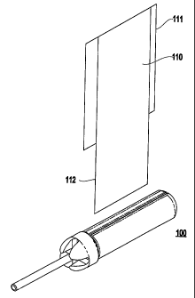
Referring now to the drawings, Figure 1 illustrates a device 100 for
connecting wire according to the present invention. For example, as shown in
Figure 1, the inventive device 100 may be used to connect a wire 110 (e.g., an
insulated flat wire) having a conductor 112 (e.g., at least one conductor) and
an
outer insulation layer 111 to another device such as a conventional appliance
or
device (e.g., a source/target device).
Specifically, the inventive device 100 may be used to connect a wire (e.g.,
a plurality of wires) to another device or structure, for example, for
transmitting or
receiving a transmission. An advantage of the inventive device 100 is that it
may
maintain the impedance and other electromagnetic propagation characteristics
of
the wire through the connection. In other words, there is almost no contact
resistance involved with the inventive device 100.
6
CA 02476253 2004-08-11
WO 03/069732 PCT/US03/04372
The inventive device 100 may be used to connect wire having various
sizes and shapes. In other words, the inventive device 100 is not necessarily
limited with respect to the size or shape of wire connected thereby. The wire
may
be, for example, an insulated wire having a conductor formed of a metallic,
metallic alloy or conductive material and may be flexible. The conductor(s) of
the
wire should be of sufficient gauge and resilience to allow it to be safely
used for
its respective application. For example, the wire types may include speaker
wire,
phone wire, data wire, or wire for carrying, for example, standard household
110
volt AC electricity.
As shown in Figure 2, the inventive device 100 may include a conductive
connector barrel 210 (e.g., a conductive rod). The connector barrel 210 may be
made, for example, of a conductive material or metal such as zinc. Further,
the
connector barrel 210 may also be plated (e.g., with a metal such as copper,
nickel,
or gold) to improve the characteristics of the connector barrel 210.
The connector barrel 210 may also have a basically cylindrical shape (e.g.,
have a circular cross-section), as shown in Figure 2. However, the connector
barrel 210 does not have to have a strictly cylindrical shape, but may be
generally
cylindrical and having flat sides. For example, the connector barrel 210 may
have
two flat sides on opposite sides of the connector barrel 210, as shown in
Figure 1.
The connector barrel 210 may also have other shapes, such as an elliptical
cross-
section.
Further, the connector barrel 210 includes a slot 215 into which a
conductor 112 (e.g., a plurality of conductors) of a wire 110 may be inserted.
7
CA 02476253 2004-08-11
WO 03/069732 PCT/US03/04372
Therefore, when the connector barrel 210 is rotated, the conductor(s) 112 may
be
applied or wound so as to electrically connect the conductor(s) 112 and
thereby
the wire 110 to the connector barrel 210.
The slot 215 in the connector barrel 210 may thus have a length
and width sufficient to insert the conductor(s) 112 (e.g., slightly longer and
wider
than the conductors), or a portion thereof, to be connected, and facilitate
the
application of the conductor(s) 112 of the wire when the connector barrel 210
is
rotated. For instance, to facilitate the application of the conductor(s), the
slot 215
may have a sharp edge at the outer surface of the connector barrel 210.
Further, the slot 215 may go through (e.g., all the way through) the center
of the connector barrel 210. The inner walls of the slot 215 may also be
plated
(e.g., copper, nickel or gold plated) as with the connector barrel 210
generally.
For instance, Figures 3A-3B illustrate the device 100 having a wire (e.g., a
conductor 112 of a wire) inserted therein, and a cross-sectional view along
lines I-
I. In particular, the cross-sectional view of Figure 3B shows the conductor
112 of
a wire inserted into the inventive device 100 and applied around the connector
barrel 210.
Referring again to Figure 2, the inventive device 100 also includes an
insulating sleeve 220. The insulating sleeve 220 may be substantially rigid
(e.g.,
being only slightly bendable) and formed of many conventional electrically
insulating materials. For example, the insulating sleeve 220 may be formed of
a
thermoplastic such as acrylonitrile butadiene styrene (ABS). In addition, the
insulating sleeve 220 may be translucent to allow a user to see through the
8
CA 02476253 2004-08-11
WO 03/069732 PCT/US03/04372
insulating sleeve 220 to the connector barrel 210 and conductor(s) 112 of the
wire
110 contained therein. Further, the insulating sleeve 220 may be color-coded
to
indicate a characteristic (e.g., polarity, ground, etc.) of the conductor(s)
112
contained therein.
As shown in Figure 2, the insulating sleeve 220 may have a shape
generally of a hollow cylinder having one end 222 open (e.g., completely open)
so
that the connector barrel 210 may be inserted therein, and another end 223
which
is only partially open. More specifically, the sleeve 220 may have a
substantially
cylindrical shape and have an inner diameter which is slightly larger than an
outer
diameter of the connector barrel 210 so that the insulating sleeve 220 may be
slid
onto the connector barrel 210 to provide an interference fit when conductor(s)
are
applied. Further, the insulating sleeve 220 should be long enough to cover the
length of the connector barrel 210.
For instance, Figure 4A-4C illustrate the device 100 and opposing axial
views of the device 100. Specifically, Figure 4C provides an axial view (i.e.,
end
view) of the partially open end 223 of the insulating sleeve 220. The
partially
open end 223 is not closed so as to allow the insulating sleeve 220 to expand
to
allow for the conductor(s) of a wire to be wrapped around the connector barrel
210 inside the insulating sleeve 220. The insulating sleeve 220 may also have
an
outer surface that is roughened (e.g., textured) to provide a better gripping
surface
for the user.
Further, the insulating sleeve 220 may compress the conductor(s) around
the connector barrel 210. The inventors have determined that a flexible
feature of
9
CA 02476253 2004-08-11
WO 03/069732 PCT/US03/04372
the insulating sleeve 210 helps to ensure a high contact pressure between the
conductor(s) 112 and the connector barrel 210. Further, the contact pressure
may
be uniform (e.g., constant) across the width of the conductor(s). Further, the
high
contact pressure and large surface contact area provided by the connector
barrel
210 help to ensure that the inventive device 100 exhibits substantially zero
contact
resistance. Therefore, unlike conventional connectors, with the inventive
device
100 there is no reduction in performance because of the connection.
In addition, the wall of the insulating sleeve 220 may have a thickness
which is sufficient to provide electrically insulating qualities, and so the
thickness
may vary depending upon the particular application. In other words, for more
powerful electrical applications, the walls of the insulating sleeve 220 may
be
thicker to provide better insulation, than for low power applications.
Further, as shown in Figures 4B-4C, the insulating sleeve 220 may include
a slot 225 through which the conductor(s) of a wire may be connected to the
connector barrel 210. For instance, the slot 225 may have a width comparable
to a
width of the slot 215 in the connector barrel 210. Further, as shown in Figure
4B,
the slot 225 may extend almost from one end of the insulating sleeve 220 to
the
other (e.g., from end 222 to end 223).
Thus, when the insulating sleeve 220 is slid onto the connector barrel 210,
the conductor(s) of the wire may be inserted simultaneously into the slot 225
of
the insulating sleeve 220 and the slot 215 of the connector barrel 210. The
connector barrel 210 may then be wound to apply the conductor(s) 112 and
tightly
secure the conductor(s) in and around the connector barrel 210, in the
inventive
CA 02476253 2004-08-11
WO 03/069732 PCT/US03/04372
device 100.
Alternatively, the conductor(s) 112 may be inserted into the slot 215 in the
connector barrel 210, the connector barrel may then be wound to apply the
conductor(s) securely around the connector barrel and the connector barrel 210
may then be inserted into the insulating sleeve 220, with the connector barrel
210
oriented so that the conductor(s) are inserted into the slot 225 of the
insulating
sleeve. In other words, the connector barrel 210 may be inserted into the
insulating sleeve 220 either before or after the conductor(s) are inserted
into the
connector barrel 210.
In fact, the insulating sleeve 220 may be slid onto the connector barrel 210
either before or after the connector barrel 210 is rotated to apply the
conductor(s).
For example, before the connector barrel 210 is inserted into the insulating
sleeve
220, the user may apply the conductor(s) 112 around the connector barrel 210
using his hand or other device. On the other hand, the user may insert the
connector barrel 210 into the insulating sleeve 220 and use the slot 225 and
inside
surface of the insulating sleeve to apply the conductor(s) around the
connector
barrel 210.
Further, as shown in Figure 2, the inventive device 100 may also include a
rotating cap 230 which is affixed (e.g., temporarily or permanently) to one
end of
the connector barrel 210. The rotating cap 230 maybe employed by a user to
facilitate easy rotation of the connector barrel 210. Specifically, by
rotating the
rotating cap 230, the user may easily rotate the connector barrel 210 either
in or
out of the insulating sleeve 220.
11
CA 02476253 2004-08-11
WO 03/069732 PCT/US03/04372
The rotating cap 230 may be formed of an electrically insulating material.
For example, the rotating cap 230 may be formed of the same material as the
insulating sleeve 220. Further, the rotating cap 230 may have similar
characteristics as the insulating sleeve 220 (e.g., translucent, transparent,
opaque,
color-coding, outer diameter, etc.,) to provide a substantially uniform outer
appearance to the inventive device 100. In addition, the rotating cap 230 may
have a diameter larger than the diameter of the insulating sleeve 220 to
provide a
larger gripping surface for the user. Further, the outer surface of the
rotating cap
230 may be roughened (e.g., include notches or grooves) to make it easier for
a
user to grip and turn the rotating cap 230.
Further, the rotating cap 230 may be affixed to the connector barrel 210 by
adhesive (e.g., glue or epoxy) or may be merely tightly form-fitted so that no
adhesive is required. In addition, the outer surface of the end of the
connector
barrel 210 onto which the rotating cap 230 is affixed, and/or the inner
surface of
the rotating cap 230 may be roughened (e.g., slotted or notched) to enhance
the fit
and prevent the rotating cap 230 from slipping on the connector barrel 210.
Further, Figure 4A shows an axial view (e.g., end view) of the rotating cap
230. The rotating cap 230 may include an indicator 235 (e.g., slots, marks,
etc.)
to indicate to the user a degree of rotation (e.g., 90 ) of the rotating cap
230. For
example, a user may use the indicator 235 to control a degree of rotation of
the
rotating cap 230 so as to control application of the conductor(s) on the
connector
barrel 210.
For example, Figure 3B (and Figure 5) illustrates a cross-sectional view of
12
CA 02476253 2004-08-11
WO 03/069732 PCT/US03/04372
the device along lines I-I (e.g., see Figure 3A). Figure 5 (similarly to
Figure 3B)
illustrates a larger cross-sectional view of the device 100 having a conductor
112
of a wire inserted therein. Figures 3B and 5, shows the rotating cap 230
having a
larger diameter than the insulating sleeve 220, and the conductor 112 of a
wire
110 being applied around the connector barrel 210. Specifically, Figures 3B
and 5
illustrate an example where the rotating cap 230 has been rotated 360 (e.g.,
one
complete turn) so that the conductor 112 of the wire 110 is around (e.g.,
completely around) the connector barrel 210.
Referring again to Figure 2, the inventive device 100 may include a
termination 240 (e.g., flat wire to conventional wire termination). The
termination 240 may be used, for example, to connect the device 100 (e.g.,
connect the conductor of a wire inserted in the device 100) to another device
such
as an amplifier, a stereo tuner, or the like.
Specifically, the termination 240 may be formed of a strand of wire or
conductor (e.g., an electrically conductive metal such as copper, silver
alloys, or
gold plated metals) or other standard interconnects, such as Banana Jacks, or
RCA
connectors. Further, the termination 240 may be connected to the connector
barrel
210 (e.g., the end of the connector barrel 210). For example, the termination
may
be securely connected (e.g., permanently or temporarily) to the connector
barrel
210 by crimping, soldering, welding, mechanical connection, or may be
integrally
formed with the contact rod 110 as one unit.
Further, the termination 240 may be formed of a thin wire (e.g., conductor)
having a thickness (e.g., diameter) of about 80/1000 inches. However, it
should
13
CA 02476253 2004-08-11
WO 03/069732 PCT/US03/04372
be noted that the thickness of the termination 240 may vary and may, for
example,
be dictated by the particular application of the device 100. For example, if
the
device 100 is used to connect wire to a stereo or phone line, the termination
240
may be substantially smaller than more powerful applications.
It should also be noted that the contact area between the surface of the
connector barrel 210 and the conductor(s) of the wire connected thereby, may
be
substantially larger than the cross-sectional area of the termination 240.
This may
ensure, for example, that the inventive device 100 has almost no contact
resistance
and that there is no reduction in performance due to the connection.
The unique device 100 creates a greatly enhanced contact surface area.
For example, the contact surface area for 110 V AC may range from 196 to 392
times greater than cross-sectional gauge area for solid core round wire. For
example, a single conductive layer would be 392 times greater than cross-
sectional gauge area for solid core round wire and two or more layers would be
196 times greater than cross-sectional gauge area for solid core round wire.
This
contact surface area may be varied, for example, by varying the width and
number
of layers of the wire conductor and the length and diameter of the connector
rod
barrel.
Referring now to Figures 6A-6B, the inventive device 100 may further
include a template 600, 650 for stabilizing the wire (e.g., reducing a strain
on the
wire). Specifically, Figure 6A illustrates a template 600 which may be used on
wire (e.g., an insulated wire) having a single conductor and Figure 6B
illustrates a
template 650 which may be used on for a wire (e.g., an insulated wire) having
2-
14
CA 02476253 2004-08-11
WO 03/069732 PCT/US03/04372
conductors. The template 600, 650 may be secured to the wire (e.g., on the
insulation) before the conductor(s) of the wire are inserted into the
connector
barrel 210. The template 600, 650 maybe formed of a material (e.g., a plastic
such as polyester film, etc.) and may be secured (e.g., by adhesive, bonding,
fusing or the like) to the wire to be connected by the inventive device 100.
For
example, the template 600, 650 may be wrapped around the outside of an
insulated wire and adhered to the insulation.
The template 600, 650 improves the durability of (e.g., provide strain relief
to) the end of the insulation and wire which is to be inserted into the
inventive
device 100. For instance, the template 600 may help to prevent the end of the
insulation surrounding the conductor(s) from tearing.
Further the template 600, 650, after it is applied to the wire, may serve to
limit the amount of conductor(s) which may be wound or applied around the
connector barrel 210.
Further, the template 600, 650 may provide a guide for cutting the
insulation around the conductor(s)which is to be connected by the device 100.
For instance, as shown in Figures 6A-6B, the user may fold the template along
a
fold line 601, 602 and align an end 610, 611 of the template 600, 650 with the
end
of the conductor(s) of the wire to be inserted into the device 100. A user may
then use the indicators 620, 621 (e.g., lines) on the template 600, 650 to cut
the
template 600, 650 to peel back the insulation on the wire to expose a
sufficient
portion of the conductor(s) to be inserted into the device 100. In addition,
as
shown in Figure 6B, the template 650 may include an indicator 631 for
indicating
CA 02476253 2010-04-08
where to cut the template 650 and insulation around the conductor(s) to
provide sufficient
movement to allow the user to work with the end of the wire. Further, the
template 600,
650 may include other indicia 661,662 (e.g., aesthetic indicia).
Referring again to the drawings, Figure 7 shows the inventive device 100
having a
flat insulated wire 1 10 connected thereto. Specifically, the insulation
around the
conductor(s) in the wire. 110 has been stripped back to expose the (e.g.,
conductor) inside
the insulated wire 1 10 and the exposed conductor(s) has been inserted into
the connector
device. The device 100 may be used to connect a flat wire having a thickness
of no more
than about 0.050 inches. For example, the inventive device 100 may be used to
connect
the multipurpose wire disclosed in U. S. Pat. No. 6,107,577.
Further, such a flat wire may include a conductor (e.g., plurality of
conductors)
which is formed as a conductive layer (e.g., a plurality of conductive
layers). For instance,
the conductive layers may be stacked on top of each other so that they may be
inserted
together into one connector barrel 210 in the inventive device 100. More
specifically, the
conductive layers may each have a thickness of about 0.0004 to 0.020 inches
(e.g., about
0.0020 inches), all of which is surrounded by a thin insulating film.
Further, the inventive device 100 may be used to connect a multiple-conductor
(e.g., 2 conductor, 3-conductor, etc.) wire in a substantially parallel and co-
planar
arrangement, contained in one insulation film. As with a single conductor
wire, each
conductor may have a plurality of conductive layers which are substantially co-
planar and
parallel. For instance, the wire may include two
16
CA 02476253 2004-08-11
WO 03/069732 PCT/US03/04372
substantially coplanar and parallel conductors, each conductor having two
conductive layers stacked one on another.
Further, the conductors in a wire having a plurality of conductors
may be inserted into a single device 110. Alternatively, each conductor may be
connected by a separate device 100. In other words, each conductor may be
inserted into a separate connector barrel 210 and insulating sleeve 220 so
that each
conductor is connected separately to another device.
In addition, the inventive device 100 may be used to connect a plurality of
wires together. For example, the inventive device 100 may be used with or
without the termination 240 so that the two separate lengths of wire may be
connected, for example, to make one length of wire.
Referring again to the figures, as shown in Figure 8, the present invention
also includes an inventive method 800 for connecting wire.
As shown in Figure 8, the inventive method 800 uses a connecting device
having a connector barrel and insulating sleeve. Specifically, the inventive
method includes inserting (810) the conductor(s) of a wire into a slot in the
connector barrel. The inventive method also includes rotating (820) the
connector
barrel to crimp the conductor(s) around the connector barrel and form an
electrical
connection. The inventive method 800 also includes inserting (830) the
connector
barrel into the insulating sleeve so that the conductor(s) contact the
connector
barrel through a slot in the insulating sleeve. The inventive method 800 may
also
include affixing a template over the wire to secure the wire during a
connection.
An exemplary embodiment of the inventive method is shown in Figure 9.
17
CA 02476253 2004-08-11
WO 03/069732 PCT/US03/04372
In this exemplary embodiment, a template may be formed over the wire to secure
the wire. This embodiment also includes exposing (810) conductor(s) in the
wire
by trimming the wire insulation material either using template 600, 650 or by
cutting around insulating material. The method may proceed by inserting (820)
the conductor(s) into the aligned insulating sleeve slot and the conductive
rod
(e.g., connector barrel) slot. The electrical connection may be made by
rotating
(830) the conductive rod by turning the rotation cap on the end of said
conductive
rod to apply the conductor(s) around the surface of the conductive rod until
the
conductor(s) is halted by the wire insulation or the strain relief template
around
the until the template 600, 650 stops the rotation. The method may also
include
connecting (940) the conductive rod to an appliance or device (e.g., a
conventional appliance or device).
Another example of the inventive method is shown in Figure 10. As
shown in Figure 10, the inventive method may include exposing (1010)
conductor(s) in the wire by trimming the wire insulation material either using
template 600, 650 or by cutting around insulating material, and inserting
(1020)
the exposed conductors into the connector barrel slot and rotating connector
barrel
to apply the conductor(s) to form an electrical connection. The method may
proceed by aligning (1030) the slot in the insulating sleeve with the wire
edge and
sliding the insulating sleeve over the applied conductor(s) and conductive rod
barrel to create an interference connection. The method may also include
connecting (1040) the connector barrel (e.g., conductive rod) to an appliance
or
device (e.g., a conventional appliance or device).
18
CA 02476253 2004-08-11
WO 03/069732 PCT/US03/04372
Therefore, with its unique and novel features, the present invention
provides a tight, stable wire connecting device and method. The inventive
device
100 provides a large surface area for contact to minimize contact resistance.
Further, the inventive device 100 helps to ensure that a contact pressure is
evenly
applied over the surface area of the connector barrel 210 and conductor(s). In
addition, the contact area provided by the inventive device 100 is
substantially air-
tight to enhance resistance or corrosion of the various components of the
wires or
conductors that are applied to the inventive device. Furthermore, the
resulting
contact is also very durable and resistant to mechanical failure because of
the
secure connection provided by the inventive device 100. This includes
resistance
to vibration and external pull forces which can cause subsequent loss of
electrical
contact. The inventive device 100 also maintains this large surface contact
area
over the life of the device. Furthermore the device can be reused many times
over
the life of the device such as when a user moves and rewires at a new location
While the invention has been described in terms of preferred
embodiments, those skilled in the art will recognize that the invention can be
practiced with modification within the spirit and scope of the appended
claims.
For example, although the invention is shown herein connecting an insulated
wire,
the invention may also be used to connect non-insulated wire. Further,
although
the invention is shown herein connecting one wire and one conductor, it should
be
understood that the invention may be used to connect a plurality of wires and
a
plurality of conductors.
19