Language selection

Search

Patent 2476470 Summary

Third-party information liability

Some of the information on this Web page has been provided by external sources. The Government of Canada is not responsible for the accuracy, reliability or currency of the information supplied by external sources. Users wishing to rely upon this information should consult directly with the source of the information. Content provided by external sources is not subject to official languages, privacy and accessibility requirements.

Claims and Abstract availability

Any discrepancies in the text and image of the Claims and Abstract are due to differing posting times. Text of the Claims and Abstract are posted:

  • At the time the application is open to public inspection;
  • At the time of issue of the patent (grant).
(12) Patent Application: (11) CA 2476470
(54) English Title: TURBINE AIRFOIL COOLING FLOW PARTICLE SEPARATOR
(54) French Title: SEPARATEUR DE PARTICULES D'UN COURANT D'AIR DE REFROIDISSEMENT POUR PROFIL DE TURBINE
Status: Deemed Abandoned and Beyond the Period of Reinstatement - Pending Response to Notice of Disregarded Communication
Bibliographic Data
(51) International Patent Classification (IPC):
  • F2C 7/052 (2006.01)
  • F1D 5/18 (2006.01)
  • F1D 25/32 (2006.01)
(72) Inventors :
  • HUDSON, ERIC A. (United States of America)
(73) Owners :
  • UNITED TECHNOLOGIES CORPORATION
(71) Applicants :
  • UNITED TECHNOLOGIES CORPORATION (United States of America)
(74) Agent: NORTON ROSE FULBRIGHT CANADA LLP/S.E.N.C.R.L., S.R.L.
(74) Associate agent:
(45) Issued:
(22) Filed Date: 2004-08-04
(41) Open to Public Inspection: 2005-02-28
Examination requested: 2004-08-04
Availability of licence: N/A
Dedicated to the Public: N/A
(25) Language of filing: English

Patent Cooperation Treaty (PCT): No

(30) Application Priority Data:
Application No. Country/Territory Date
10/652,913 (United States of America) 2003-08-28

Abstracts

English Abstract


A vane assembly for a turbine engine comprising a plurality of vanes each
comprising
a pressure side wherein the pressure side of at least one of the plurality of
vanes comprises at
least one opening extending through the pressure side into an interior portion
of the at least
one of the plurality of vanes.


Claims

Note: Claims are shown in the official language in which they were submitted.

CLAIMS
1. A vane assembly for a turbine engine comprising:
a plurality of vanes each comprising a pressure side wherein said pressure
side of at
least one of said plurality of vanes comprises at least one opening extending
through said
pressure side into an interior portion of said at least one of said plurality
of vanes.
2. The particle separator of claim 1 wherein each of said at least one opening
comprises
a diameter less than 1.5 millimeters.
3. The particle separator of claim 1 wherein between 1% and 25% of said
pressure side
is covered by said at least one opening.
4. The particle separator of claim 1 wherein at least one of said at least one
opening is
formed by a slot.
5. The particle separator of claim 1 wherein said plurality of vanes comprise
turbine
engine turning vanes.
6. A method for removing particles from engine airflow comprising the steps
of:
providing at least one opening through a pressure side of a vane;
passing airflow containing contaminating particles across said pressure side
of said
vane; and
collecting said contaminating particles which pass through said at least one
opening.
7. The method of claim 6 wherein collecting said contaminating particles
comprises the
steps of:
receiving said contaminating particles in an interior cavity; and
moving said contaminating particles from said interior cavity to a venting
location.
5

Description

Note: Descriptions are shown in the official language in which they were submitted.


CA 02476470 2004-08-04
EH-10730 (02-632) ~ r ~ ~ ' ~ -' ''
TURBINE AIRFOIL COOLING FLOW PARTICLE SEPARATOR
U.S. GOVERNMENT RIGHTS
The invention was made with U.S. Government support under contract F33615-97-
C-2779 awarded by the U.S. Air Force. The U.S. Government has certain rights
in the
invention.
BACKGROUND OF THE INVENTION
( 1 ) Field of the Invention
The present invention relates an inertial particle separator for cooling air
provided
to turbine blades.
(2~Description of the Related Art
Gas turbine engine design and construction requires ever increasing efficiency
and
performance. In order to achieve such increased efficiency and performance,
often times the
combustion component of the engine is modified such that exit temperatures are
elevated.
However, turbine airfoil temperature capability must be raised in such
instances owing to the
need for durability. In response to this need, various methods have been
introduced to
improve the cooling technology employed on turbine blades. These cooling
schemes employ
small holes and passages for cooling air flow. The most advanced cooling
designs employ
progressively smaller cooling features. Unfortunately, these small features
are prone to
plugging by dirt particulates. Such dirt particulates may derive from the
external engine
environment, fuel contaminates, less than fully burned fuel particulates, and
other various
sources of particulate matter. By clogging the cooling features, the dirt
particulates result in
the burning and oxidation of the airfoils.
What is therefore needed is a method for separating contaminating particles in
order to improve the longevity of new technology air foil cooling schemes
which make use of
small internal cooling features. It is additionally necessary to improve and
to decrease the
incidence of airfoil cooling passage plugging present in existing designs.
SUMMARY OF THE INVENTION
Accordingly, it is an object of the present invention to provide an inertial
particle
separator for cooling air provided to turbine blades.
It is a further object of the present invention to provide a vane assembly for
a
turbine engine which comprises a plurality of vanes each comprising a pressure
side wherein
the pressure side of at least one of the plurality of vanes comprises at least
one opening

EH-10730 (02-632)
CA 02476470 2004-08-04
extending through the pressure side into an interior portion of the at least
one of the plurality
of vanes.
It is a further object of the present invention to provide a method for
removing
particles from engine airflow which comprises the steps of fabricating at
least one opening
through a pressure side of a vane passing airflow comprising contaminating
particles across
the pressure side of the vane, collecting the contaminating particles which
pass through the at
least one opening.
BRIEF DESCRIPTION OF THE DRAWINGS
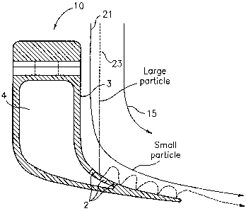
FIG. 1 is a diagram of the turning vanes of the present invention.
FIG. 2 is a diagram of the turning vanes of the present invention showing the
increased turn gas flow direction.
FIG. 3 is a diagram of the turning vanes of the present invention illustrating
the
path of exemplary large and small particles.
FIG. 4 is a graph illustrating the probability of capture as a function of
particle
size.
DETAILED DESCRIPTION
It is therefore the primary objective of the present invention to provide an
inertial
particle separator for cooling air provided to turbine blades. The object of
the present
invention is primarily achieved by adding one or more slots, or openings, to
existing turning
vanes of a size and orientation sufficient to capture and evacuate particles
present within the
airflow. As will be described more fully below, particles present in the
airflow tend to travel
along the pressure side of turning vanes. Depending on the size and the mass
of the particles
contained within the airflow, the inertia of the particles may be used to
capture the particles
as they impact upon the pressure side of the turning vane. By including a
series of openings
or slots in the wall of the airfoil, it is possible to capture a considerable
percentage of
particles as the airflow moves through the turning vanes.
With reference to Fig. 1 there is illustrated a plurality of turning vanes 10
of the
present invention. While illustrated with reference to the TOBI (Tangential
Onboard
Injection) system, the turning vanes of the present invention are no so
limited. Rather, the
present invention encompasses any and all vane utilized to reduce pressure
losses and reduce
the cooling air temperature of the cooling air supplied to the blades of an
engine. As can be
2

EH-10730 (02-632)
CA 02476470 2004-08-04
seen, fuming vanes 10 are comprised of an interior cavity 4. An external edge
of each
turning vane 10 corresponds to the pressure side 3 of the turning vane. There
is indicated
airflow 15 which flows generally in a direction corresponding to pressure side
3. Note that a
plurality of openings 2, or slots, have been fabricated into pressure side 3
commencing at a
point at or after the turning area 17 of the vane 10. As used herein, "turning
area" refers to the
area of the vane located on the pressure side of the vane, starting at or near
the point of
maximum turn on the pressure side of the vane, and extending in the direction
of airflow 15.
Particles, embedded in airflow 15, may pass through the openings 2 and enter
into the interior
cavity 4. Due to their higher mass, dirt particles are less able to turn with
the air molecules
comprising airflow 15 and are concentrated on the pressure side 3 of the
airflow. As a result,
particles can be removed through openings 2. After passing through opening 2
and into
interior cavity 4, the dirty air containing the dirt particles is passed
through the interior cavity
for venting to a venting location 31 less sensitive to dirt contamination.
Venting location 31 is
preferably maintained at a lower pressure than is interior cavity 4 in order
to provide a
suction force sufficient to draw the airflow required to conduct dirt
particles from the main
airflow stream.
With reference to Fig. 3 there is illustrated the path of both relatively
large
particles and relatively small particles. Small particle path 21 represents
the path followed by
an exemplary small particle. Large particle path 23 represents the path
followed by an
exemplary large particle traveling in the general direction of airflow 15.
Note that, because
of the increased mass and inertia of the large particles traveling along the
large particle path
23, the large particles impact pressure side 3 of turning vane 10 and proceed
to bounce
several times as they travel in the general direction of airflow 15. In
contrast, small particles
traveling along small particle path 21 tend, because of their smaller mass and
lower inertia, to
continue along with airflow 15 past turning vane 10. As is evident, because of
the tendency
for large particles to bounce several times as they move in correspondence
with airflowl5,
increasing the number of openings 2 to forming passage ways into interior
cavity 4 increases
the likelihood of capturing any given large particle. In order to increase the
likelihood of
capturing small particles traveling along small particle path 21, it is
preferable to increase the
degree of turning experienced by the small particles. With reference to Fig.
2, there is
illustrated an increased turn gas flow direction 13 arises from rotating each
of the plurality of
turning vanes 10 so as to increase the maximum amount of turn present at a
maximum turn
area 17, and along increased turn gas flow direction 13. In a preferred
embodiment, the
3

EH-10730 (02-632)
CA 02476470 2004-08-04
openings are less than 1.5 millimeters as measured in the direction of airflow
15. Preferably,
the total amount of pressure side 3 removed by the openings 2 is between 1 %
and 25%.
The aforementioned insights are graphically represented in figure 4. As is
evident,
the probability of capture, or "POC" as a function of particles size forms a
generally Gaussian
curve. That is to say, as the particle size approaches zero very few if any
particles are
captured and, additionally, as the particle size approaches a very large size,
few large
particles are captured. To the left hand side of the Gaussian curve there are
two exemplary
dotted curves drawn to illustrate the increasing likelihood of capturing
particles of any
particular small size by steadily increasing the turning angle of increased
turn gas flow
direction 13 as described above. Likewise, to the right hand side of the
curve, there are two
exemplary dotted graph lines drawn to show the increased likelihood of
capturing large
particles as a result of increasing number slots.
It is apparent that there has been provided in accordance with the present
invention
an inertial particle separator for cooling air provided to turbine blades
which fully satisfies
the objects, means, and advantages set forth previously herein. While the
present invention
has been described in the context of specific embodiments thereof, other
alternatives,
modifications, and variations will become apparent to those skilled in the art
having read the
foregoing description. Accordingly, it is intended to embrace those
alternatives,
modifications, and variations as fall within the broad scope of the appended
claims.
4

Representative Drawing
A single figure which represents the drawing illustrating the invention.
Administrative Status

2024-08-01:As part of the Next Generation Patents (NGP) transition, the Canadian Patents Database (CPD) now contains a more detailed Event History, which replicates the Event Log of our new back-office solution.

Please note that "Inactive:" events refers to events no longer in use in our new back-office solution.

For a clearer understanding of the status of the application/patent presented on this page, the site Disclaimer , as well as the definitions for Patent , Event History , Maintenance Fee  and Payment History  should be consulted.

Event History

Description Date
Application Not Reinstated by Deadline 2010-08-04
Time Limit for Reversal Expired 2010-08-04
Deemed Abandoned - Conditions for Grant Determined Not Compliant 2009-09-03
Deemed Abandoned - Failure to Respond to Maintenance Fee Notice 2009-08-04
Notice of Allowance is Issued 2009-03-03
Letter Sent 2009-03-03
4 2009-03-03
Notice of Allowance is Issued 2009-03-03
Inactive: Approved for allowance (AFA) 2009-02-23
Amendment Received - Voluntary Amendment 2008-11-21
Inactive: S.30(2) Rules - Examiner requisition 2008-08-14
Amendment Received - Voluntary Amendment 2007-12-10
Inactive: S.30(2) Rules - Examiner requisition 2007-06-12
Inactive: IPC from MCD 2006-03-12
Application Published (Open to Public Inspection) 2005-02-28
Inactive: Cover page published 2005-02-27
Inactive: First IPC assigned 2005-02-17
Letter Sent 2004-11-09
Inactive: Single transfer 2004-09-30
Inactive: Courtesy letter - Evidence 2004-09-21
Inactive: Filing certificate - RFE (English) 2004-09-14
Letter Sent 2004-09-14
Application Received - Regular National 2004-09-14
Request for Examination Requirements Determined Compliant 2004-08-04
All Requirements for Examination Determined Compliant 2004-08-04

Abandonment History

Abandonment Date Reason Reinstatement Date
2009-09-03
2009-08-04

Maintenance Fee

The last payment was received on 2008-07-29

Note : If the full payment has not been received on or before the date indicated, a further fee may be required which may be one of the following

  • the reinstatement fee;
  • the late payment fee; or
  • additional fee to reverse deemed expiry.

Patent fees are adjusted on the 1st of January every year. The amounts above are the current amounts if received by December 31 of the current year.
Please refer to the CIPO Patent Fees web page to see all current fee amounts.

Fee History

Fee Type Anniversary Year Due Date Paid Date
Application fee - standard 2004-08-04
Request for examination - standard 2004-08-04
Registration of a document 2004-09-30
MF (application, 2nd anniv.) - standard 02 2006-08-04 2006-07-19
MF (application, 3rd anniv.) - standard 03 2007-08-06 2007-07-30
MF (application, 4th anniv.) - standard 04 2008-08-04 2008-07-29
Owners on Record

Note: Records showing the ownership history in alphabetical order.

Current Owners on Record
UNITED TECHNOLOGIES CORPORATION
Past Owners on Record
ERIC A. HUDSON
Past Owners that do not appear in the "Owners on Record" listing will appear in other documentation within the application.
Documents

To view selected files, please enter reCAPTCHA code :


To view images, click a link in the Document Description column (Temporarily unavailable). To download the documents, select one or more checkboxes in the first column and then click the "Download Selected in PDF format (Zip Archive)" or the "Download Selected as Single PDF" button.

List of published and non-published patent-specific documents on the CPD .

If you have any difficulty accessing content, you can call the Client Service Centre at 1-866-997-1936 or send them an e-mail at CIPO Client Service Centre.

({010=All Documents, 020=As Filed, 030=As Open to Public Inspection, 040=At Issuance, 050=Examination, 060=Incoming Correspondence, 070=Miscellaneous, 080=Outgoing Correspondence, 090=Payment})


Document
Description 
Date
(yyyy-mm-dd) 
Number of pages   Size of Image (KB) 
Description 2004-08-03 4 222
Abstract 2004-08-03 1 9
Drawings 2004-08-03 2 42
Claims 2004-08-03 1 33
Representative drawing 2005-02-02 1 10
Description 2007-12-09 5 218
Claims 2007-12-09 2 66
Claims 2008-11-20 2 41
Acknowledgement of Request for Examination 2004-09-13 1 185
Filing Certificate (English) 2004-09-13 1 168
Courtesy - Certificate of registration (related document(s)) 2004-11-08 1 106
Reminder of maintenance fee due 2006-04-04 1 112
Commissioner's Notice - Application Found Allowable 2009-03-02 1 163
Courtesy - Abandonment Letter (Maintenance Fee) 2009-09-28 1 172
Courtesy - Abandonment Letter (NOA) 2009-11-25 1 164
Correspondence 2004-09-13 1 26