Sélection de la langue

Search

Sommaire du brevet 2476470 

Énoncé de désistement de responsabilité concernant l'information provenant de tiers

Une partie des informations de ce site Web a été fournie par des sources externes. Le gouvernement du Canada n'assume aucune responsabilité concernant la précision, l'actualité ou la fiabilité des informations fournies par les sources externes. Les utilisateurs qui désirent employer cette information devraient consulter directement la source des informations. Le contenu fourni par les sources externes n'est pas assujetti aux exigences sur les langues officielles, la protection des renseignements personnels et l'accessibilité.

Disponibilité de l'Abrégé et des Revendications

L'apparition de différences dans le texte et l'image des Revendications et de l'Abrégé dépend du moment auquel le document est publié. Les textes des Revendications et de l'Abrégé sont affichés :

  • lorsque la demande peut être examinée par le public;
  • lorsque le brevet est émis (délivrance).
(12) Demande de brevet: (11) CA 2476470
(54) Titre français: SEPARATEUR DE PARTICULES D'UN COURANT D'AIR DE REFROIDISSEMENT POUR PROFIL DE TURBINE
(54) Titre anglais: TURBINE AIRFOIL COOLING FLOW PARTICLE SEPARATOR
Statut: Réputée abandonnée et au-delà du délai pour le rétablissement - en attente de la réponse à l’avis de communication rejetée
Données bibliographiques
(51) Classification internationale des brevets (CIB):
  • F2C 7/052 (2006.01)
  • F1D 5/18 (2006.01)
  • F1D 25/32 (2006.01)
(72) Inventeurs :
  • HUDSON, ERIC A. (Etats-Unis d'Amérique)
(73) Titulaires :
  • UNITED TECHNOLOGIES CORPORATION
(71) Demandeurs :
  • UNITED TECHNOLOGIES CORPORATION (Etats-Unis d'Amérique)
(74) Agent: NORTON ROSE FULBRIGHT CANADA LLP/S.E.N.C.R.L., S.R.L.
(74) Co-agent:
(45) Délivré:
(22) Date de dépôt: 2004-08-04
(41) Mise à la disponibilité du public: 2005-02-28
Requête d'examen: 2004-08-04
Licence disponible: S.O.
Cédé au domaine public: S.O.
(25) Langue des documents déposés: Anglais

Traité de coopération en matière de brevets (PCT): Non

(30) Données de priorité de la demande:
Numéro de la demande Pays / territoire Date
10/652,913 (Etats-Unis d'Amérique) 2003-08-28

Abrégés

Abrégé anglais


A vane assembly for a turbine engine comprising a plurality of vanes each
comprising
a pressure side wherein the pressure side of at least one of the plurality of
vanes comprises at
least one opening extending through the pressure side into an interior portion
of the at least
one of the plurality of vanes.

Revendications

Note : Les revendications sont présentées dans la langue officielle dans laquelle elles ont été soumises.


CLAIMS
1. A vane assembly for a turbine engine comprising:
a plurality of vanes each comprising a pressure side wherein said pressure
side of at
least one of said plurality of vanes comprises at least one opening extending
through said
pressure side into an interior portion of said at least one of said plurality
of vanes.
2. The particle separator of claim 1 wherein each of said at least one opening
comprises
a diameter less than 1.5 millimeters.
3. The particle separator of claim 1 wherein between 1% and 25% of said
pressure side
is covered by said at least one opening.
4. The particle separator of claim 1 wherein at least one of said at least one
opening is
formed by a slot.
5. The particle separator of claim 1 wherein said plurality of vanes comprise
turbine
engine turning vanes.
6. A method for removing particles from engine airflow comprising the steps
of:
providing at least one opening through a pressure side of a vane;
passing airflow containing contaminating particles across said pressure side
of said
vane; and
collecting said contaminating particles which pass through said at least one
opening.
7. The method of claim 6 wherein collecting said contaminating particles
comprises the
steps of:
receiving said contaminating particles in an interior cavity; and
moving said contaminating particles from said interior cavity to a venting
location.
5

Description

Note : Les descriptions sont présentées dans la langue officielle dans laquelle elles ont été soumises.

CA 02476470 2004-08-04
EH-10730 (02-632) ~ r ~ ~ ' ~ -' ''
TURBINE AIRFOIL COOLING FLOW PARTICLE SEPARATOR
U.S. GOVERNMENT RIGHTS
The invention was made with U.S. Government support under contract F33615-97-
C-2779 awarded by the U.S. Air Force. The U.S. Government has certain rights
in the
invention.
BACKGROUND OF THE INVENTION
( 1 ) Field of the Invention
The present invention relates an inertial particle separator for cooling air
provided
to turbine blades.
(2~Description of the Related Art
Gas turbine engine design and construction requires ever increasing efficiency
and
performance. In order to achieve such increased efficiency and performance,
often times the
combustion component of the engine is modified such that exit temperatures are
elevated.
However, turbine airfoil temperature capability must be raised in such
instances owing to the
need for durability. In response to this need, various methods have been
introduced to
improve the cooling technology employed on turbine blades. These cooling
schemes employ
small holes and passages for cooling air flow. The most advanced cooling
designs employ
progressively smaller cooling features. Unfortunately, these small features
are prone to
plugging by dirt particulates. Such dirt particulates may derive from the
external engine
environment, fuel contaminates, less than fully burned fuel particulates, and
other various
sources of particulate matter. By clogging the cooling features, the dirt
particulates result in
the burning and oxidation of the airfoils.
What is therefore needed is a method for separating contaminating particles in
order to improve the longevity of new technology air foil cooling schemes
which make use of
small internal cooling features. It is additionally necessary to improve and
to decrease the
incidence of airfoil cooling passage plugging present in existing designs.
SUMMARY OF THE INVENTION
Accordingly, it is an object of the present invention to provide an inertial
particle
separator for cooling air provided to turbine blades.
It is a further object of the present invention to provide a vane assembly for
a
turbine engine which comprises a plurality of vanes each comprising a pressure
side wherein
the pressure side of at least one of the plurality of vanes comprises at least
one opening

EH-10730 (02-632)
CA 02476470 2004-08-04
extending through the pressure side into an interior portion of the at least
one of the plurality
of vanes.
It is a further object of the present invention to provide a method for
removing
particles from engine airflow which comprises the steps of fabricating at
least one opening
through a pressure side of a vane passing airflow comprising contaminating
particles across
the pressure side of the vane, collecting the contaminating particles which
pass through the at
least one opening.
BRIEF DESCRIPTION OF THE DRAWINGS
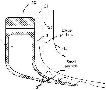
FIG. 1 is a diagram of the turning vanes of the present invention.
FIG. 2 is a diagram of the turning vanes of the present invention showing the
increased turn gas flow direction.
FIG. 3 is a diagram of the turning vanes of the present invention illustrating
the
path of exemplary large and small particles.
FIG. 4 is a graph illustrating the probability of capture as a function of
particle
size.
DETAILED DESCRIPTION
It is therefore the primary objective of the present invention to provide an
inertial
particle separator for cooling air provided to turbine blades. The object of
the present
invention is primarily achieved by adding one or more slots, or openings, to
existing turning
vanes of a size and orientation sufficient to capture and evacuate particles
present within the
airflow. As will be described more fully below, particles present in the
airflow tend to travel
along the pressure side of turning vanes. Depending on the size and the mass
of the particles
contained within the airflow, the inertia of the particles may be used to
capture the particles
as they impact upon the pressure side of the turning vane. By including a
series of openings
or slots in the wall of the airfoil, it is possible to capture a considerable
percentage of
particles as the airflow moves through the turning vanes.
With reference to Fig. 1 there is illustrated a plurality of turning vanes 10
of the
present invention. While illustrated with reference to the TOBI (Tangential
Onboard
Injection) system, the turning vanes of the present invention are no so
limited. Rather, the
present invention encompasses any and all vane utilized to reduce pressure
losses and reduce
the cooling air temperature of the cooling air supplied to the blades of an
engine. As can be
2

EH-10730 (02-632)
CA 02476470 2004-08-04
seen, fuming vanes 10 are comprised of an interior cavity 4. An external edge
of each
turning vane 10 corresponds to the pressure side 3 of the turning vane. There
is indicated
airflow 15 which flows generally in a direction corresponding to pressure side
3. Note that a
plurality of openings 2, or slots, have been fabricated into pressure side 3
commencing at a
point at or after the turning area 17 of the vane 10. As used herein, "turning
area" refers to the
area of the vane located on the pressure side of the vane, starting at or near
the point of
maximum turn on the pressure side of the vane, and extending in the direction
of airflow 15.
Particles, embedded in airflow 15, may pass through the openings 2 and enter
into the interior
cavity 4. Due to their higher mass, dirt particles are less able to turn with
the air molecules
comprising airflow 15 and are concentrated on the pressure side 3 of the
airflow. As a result,
particles can be removed through openings 2. After passing through opening 2
and into
interior cavity 4, the dirty air containing the dirt particles is passed
through the interior cavity
for venting to a venting location 31 less sensitive to dirt contamination.
Venting location 31 is
preferably maintained at a lower pressure than is interior cavity 4 in order
to provide a
suction force sufficient to draw the airflow required to conduct dirt
particles from the main
airflow stream.
With reference to Fig. 3 there is illustrated the path of both relatively
large
particles and relatively small particles. Small particle path 21 represents
the path followed by
an exemplary small particle. Large particle path 23 represents the path
followed by an
exemplary large particle traveling in the general direction of airflow 15.
Note that, because
of the increased mass and inertia of the large particles traveling along the
large particle path
23, the large particles impact pressure side 3 of turning vane 10 and proceed
to bounce
several times as they travel in the general direction of airflow 15. In
contrast, small particles
traveling along small particle path 21 tend, because of their smaller mass and
lower inertia, to
continue along with airflow 15 past turning vane 10. As is evident, because of
the tendency
for large particles to bounce several times as they move in correspondence
with airflowl5,
increasing the number of openings 2 to forming passage ways into interior
cavity 4 increases
the likelihood of capturing any given large particle. In order to increase the
likelihood of
capturing small particles traveling along small particle path 21, it is
preferable to increase the
degree of turning experienced by the small particles. With reference to Fig.
2, there is
illustrated an increased turn gas flow direction 13 arises from rotating each
of the plurality of
turning vanes 10 so as to increase the maximum amount of turn present at a
maximum turn
area 17, and along increased turn gas flow direction 13. In a preferred
embodiment, the
3

EH-10730 (02-632)
CA 02476470 2004-08-04
openings are less than 1.5 millimeters as measured in the direction of airflow
15. Preferably,
the total amount of pressure side 3 removed by the openings 2 is between 1 %
and 25%.
The aforementioned insights are graphically represented in figure 4. As is
evident,
the probability of capture, or "POC" as a function of particles size forms a
generally Gaussian
curve. That is to say, as the particle size approaches zero very few if any
particles are
captured and, additionally, as the particle size approaches a very large size,
few large
particles are captured. To the left hand side of the Gaussian curve there are
two exemplary
dotted curves drawn to illustrate the increasing likelihood of capturing
particles of any
particular small size by steadily increasing the turning angle of increased
turn gas flow
direction 13 as described above. Likewise, to the right hand side of the
curve, there are two
exemplary dotted graph lines drawn to show the increased likelihood of
capturing large
particles as a result of increasing number slots.
It is apparent that there has been provided in accordance with the present
invention
an inertial particle separator for cooling air provided to turbine blades
which fully satisfies
the objects, means, and advantages set forth previously herein. While the
present invention
has been described in the context of specific embodiments thereof, other
alternatives,
modifications, and variations will become apparent to those skilled in the art
having read the
foregoing description. Accordingly, it is intended to embrace those
alternatives,
modifications, and variations as fall within the broad scope of the appended
claims.
4

Dessin représentatif
Une figure unique qui représente un dessin illustrant l'invention.
États administratifs

2024-08-01 : Dans le cadre de la transition vers les Brevets de nouvelle génération (BNG), la base de données sur les brevets canadiens (BDBC) contient désormais un Historique d'événement plus détaillé, qui reproduit le Journal des événements de notre nouvelle solution interne.

Veuillez noter que les événements débutant par « Inactive : » se réfèrent à des événements qui ne sont plus utilisés dans notre nouvelle solution interne.

Pour une meilleure compréhension de l'état de la demande ou brevet qui figure sur cette page, la rubrique Mise en garde , et les descriptions de Brevet , Historique d'événement , Taxes périodiques et Historique des paiements devraient être consultées.

Historique d'événement

Description Date
Demande non rétablie avant l'échéance 2010-08-04
Le délai pour l'annulation est expiré 2010-08-04
Réputée abandonnée - les conditions pour l'octroi - jugée non conforme 2009-09-03
Réputée abandonnée - omission de répondre à un avis sur les taxes pour le maintien en état 2009-08-04
Un avis d'acceptation est envoyé 2009-03-03
Lettre envoyée 2009-03-03
month 2009-03-03
Un avis d'acceptation est envoyé 2009-03-03
Inactive : Approuvée aux fins d'acceptation (AFA) 2009-02-23
Modification reçue - modification volontaire 2008-11-21
Inactive : Dem. de l'examinateur par.30(2) Règles 2008-08-14
Modification reçue - modification volontaire 2007-12-10
Inactive : Dem. de l'examinateur par.30(2) Règles 2007-06-12
Inactive : CIB de MCD 2006-03-12
Demande publiée (accessible au public) 2005-02-28
Inactive : Page couverture publiée 2005-02-27
Inactive : CIB en 1re position 2005-02-17
Lettre envoyée 2004-11-09
Inactive : Transfert individuel 2004-09-30
Inactive : Lettre de courtoisie - Preuve 2004-09-21
Inactive : Certificat de dépôt - RE (Anglais) 2004-09-14
Lettre envoyée 2004-09-14
Demande reçue - nationale ordinaire 2004-09-14
Exigences pour une requête d'examen - jugée conforme 2004-08-04
Toutes les exigences pour l'examen - jugée conforme 2004-08-04

Historique d'abandonnement

Date d'abandonnement Raison Date de rétablissement
2009-09-03
2009-08-04

Taxes périodiques

Le dernier paiement a été reçu le 2008-07-29

Avis : Si le paiement en totalité n'a pas été reçu au plus tard à la date indiquée, une taxe supplémentaire peut être imposée, soit une des taxes suivantes :

  • taxe de rétablissement ;
  • taxe pour paiement en souffrance ; ou
  • taxe additionnelle pour le renversement d'une péremption réputée.

Les taxes sur les brevets sont ajustées au 1er janvier de chaque année. Les montants ci-dessus sont les montants actuels s'ils sont reçus au plus tard le 31 décembre de l'année en cours.
Veuillez vous référer à la page web des taxes sur les brevets de l'OPIC pour voir tous les montants actuels des taxes.

Historique des taxes

Type de taxes Anniversaire Échéance Date payée
Taxe pour le dépôt - générale 2004-08-04
Requête d'examen - générale 2004-08-04
Enregistrement d'un document 2004-09-30
TM (demande, 2e anniv.) - générale 02 2006-08-04 2006-07-19
TM (demande, 3e anniv.) - générale 03 2007-08-06 2007-07-30
TM (demande, 4e anniv.) - générale 04 2008-08-04 2008-07-29
Titulaires au dossier

Les titulaires actuels et antérieures au dossier sont affichés en ordre alphabétique.

Titulaires actuels au dossier
UNITED TECHNOLOGIES CORPORATION
Titulaires antérieures au dossier
ERIC A. HUDSON
Les propriétaires antérieurs qui ne figurent pas dans la liste des « Propriétaires au dossier » apparaîtront dans d'autres documents au dossier.
Documents

Pour visionner les fichiers sélectionnés, entrer le code reCAPTCHA :


Pour visualiser une image, cliquer sur un lien dans la colonne description du document (Temporairement non-disponible). Pour télécharger l'image (les images), cliquer l'une ou plusieurs cases à cocher dans la première colonne et ensuite cliquer sur le bouton "Télécharger sélection en format PDF (archive Zip)" ou le bouton "Télécharger sélection (en un fichier PDF fusionné)".

Liste des documents de brevet publiés et non publiés sur la BDBC .

Si vous avez des difficultés à accéder au contenu, veuillez communiquer avec le Centre de services à la clientèle au 1-866-997-1936, ou envoyer un courriel au Centre de service à la clientèle de l'OPIC.

({010=Tous les documents, 020=Au moment du dépôt, 030=Au moment de la mise à la disponibilité du public, 040=À la délivrance, 050=Examen, 060=Correspondance reçue, 070=Divers, 080=Correspondance envoyée, 090=Paiement})


Description du
Document 
Date
(aaaa-mm-jj) 
Nombre de pages   Taille de l'image (Ko) 
Description 2004-08-03 4 222
Abrégé 2004-08-03 1 9
Dessins 2004-08-03 2 42
Revendications 2004-08-03 1 33
Dessin représentatif 2005-02-02 1 10
Description 2007-12-09 5 218
Revendications 2007-12-09 2 66
Revendications 2008-11-20 2 41
Accusé de réception de la requête d'examen 2004-09-13 1 185
Certificat de dépôt (anglais) 2004-09-13 1 168
Courtoisie - Certificat d'enregistrement (document(s) connexe(s)) 2004-11-08 1 106
Rappel de taxe de maintien due 2006-04-04 1 112
Avis du commissaire - Demande jugée acceptable 2009-03-02 1 163
Courtoisie - Lettre d'abandon (taxe de maintien en état) 2009-09-28 1 172
Courtoisie - Lettre d'abandon (AA) 2009-11-25 1 164
Correspondance 2004-09-13 1 26