Note: Descriptions are shown in the official language in which they were submitted.
CA 02476525 2004-08-04
A METHOD OF OPERATING A DISCHARGE LAMP
Background of the Invention
The present invention is directed to a method of operating a discharge lamp
that
reduces segregation in the arc discharge tube.
Operation of an arc discharge tube with its axis other than horizontal can
lead to
segregation of vapor phase species, which in turn leads to color separation
over the length
of the arc tube, reduced light output, local overheating of the arc tube wall,
and other
problems that may cause premature lamp failure or unsatisfactory lamp
performance.
This is particularly true for lamps having high aspect ratio arc tubes (arc
tubes whose
length-to-width ratio is > about 2).
Acoustic modulation of the input lamp power has been proposed as a solution to
the segregation problem. For example, U.S. Patent No. 6,124,683 describes an
arc
discharge lamp in which the arc is straightened by acoustic modulation of the
lamp power
resulting in improved efficacy and a reduced asymmetry of the color. The
acoustic
modes of discharge lamps are known to those of skill in the art, and the
following is a
brief summary of what is known. Modulation of lamp power causes modulation of
the
arc temperature distribution and, as a result, modulation of the gas pressure
distribution
throughout the arc discharge tube of the lamp. Certain frequencies of
modulation cause
standing wave oscillation of the gas pressure in the tube. Because of the
cylindrical
shape of commercial arc discharge tubes, the acoustic modes can generally be
described
as modes of a cylinder of a size comparable to the discharge, or inner, cavity
(i.e., the
cavity in which the arc is formed) in the arc tube of the lamp. If the
pressure has a spatial
-1-
CA 02476525 2004-08-04
dependence along the axis of the tube (i.e., the cylinder of comparable size),
then the
mode is longitudinal with the number of half-wavelengths in the standing wave
determining the order of the mode. For example, if there are two half-
wavelengths, the
mode is the second longitudinal mode. If the pressure has a spatial dependence
along the
radius of the tube, then the mode is radial, and if the pressure has a spatial
dependence
around the circumference of the tube, then the mode is azimuthal. Combination
acoustic
modes are also possible, such as radial-longitudinal modes and azimuthal-
longitudinal
modes, in which the pressure distribution varies along more than one
coordinate. These
combination modes can be further defined, depending on the periodicity of the
standing
wave, such as a combination acoustic mode of the third azimuthal and second
longitudinal modes.
The resonance frequencies for each of these acoustic modes are determined by
the dimensions of the discharge cavity of the are tube and the speed of sound
in the gas
phase in the discharge cavity. In a first approximation, the speed of sound
depends on the
arc temperature and the composition of the gas phase in the discharge cavity.
More
particularly, the speed of sound is proportional to (T/m)"2 where T is the
temperature and
in is the average molecular mass of the various vapor phases constituents. In
arc tubes
having a high Xe gas fill pressure, in is approximately the mass of Xe.
Although the arc
temperature in an operating are tube is location dependent, the resonance
frequencies
nevertheless may be reasonably estimated using an isothermal cylindrical
model.
The longitudinal mode (nL) frequencies are roughly
fn L = (n*C)/(2*Length),
-2-
CA 02476525 2004-08-04
where f n1. is the nth longitudinal mode, C is the average speed of sound in
the gas phase,
and Length is the cavity length.
The radial mode (nR) frequencies are roughly
f .R = (knR*C)/(n*D)
where fnR is the nth radial mode, knR is a constant that is known for each
radial mode (it
is 3.83 for the first radial mode and higher for subsequent modes), C is the
average speed
of sound in the gas phase, and D is the diameter of the cavity.
The azimuthal mode (nA) frequencies are roughly
f nA = `knA*C)/(t*D)
where fnA is the nth azimuthal mode, k1A is a constant that is known for each
azimuthal
mode (it is 1.84 for the first azimuthal mode, 3.05 for the second, 4.20 for
the third and
higher for subsequent modes), C is the average speed of sound in the gas
phase, and D is
the diameter of the cavity.
Better estimates of the resonance frequencies can be obtained from finite
element
calculations of the eigenmodes of vessels approximating the shape of the
cavity in which
the arc is formed using well estimated temperature and composition
distributions.
For some combination modes the frequencies can be determined by combining
the frequencies of the individual modes in quadrature. For example, the
resonance
frequency of the first radial (1R) and fourth longitudinal (4L) combination
mode is:
f1R4L2=f1R2+f4L2.
These frequencies are the power modulation frequencies (denoted herein "power
frequencies"). The corresponding voltage (or current) frequencies depend on
the type of
-3-
...v ,vA. nA- a~.v..rm..+ins -'aVVmn F4d'. . - . P
CA 02476525 2011-01-18
waveform being applied. For sine waves, the corresponding current (or voltage)
frequencies
are one-half the power frequencies.
With reference again to the prior art, a further solution to the problem of
vertical
segregation is offered in U.S. Pat. No. 6,184,633 that suggests that amplitude
modulation of
an arc-straightening frequency sweep may be effective. For example, a
(current) frequency
sweep from 45 kHz to 55 kHz every ten milliseconds in a saw tooth pattern may
be
amplitude modulated at a frequency corresponding to the second longitudinal
acoustic mode
and a modulation index of 0.24. The modulation index is defined as (Vmax -
Vmin)/(Vmax
+ Vmin), where Vmax is the maximum peak-to-peak voltage of the amplitude
modulated
envelope and Vmin is the minimum peak-to-peak voltage of the amplitude
modulated
envelope. This reference points out that amplitude modulation at a frequency
corresponding
to the first longitudinal acoustic mode is less effective than the preferred
frequency
corresponding to the second longitudinal acoustic mode, although vertical
segregation is
reduced somewhat with amplitude modulation at the frequency corresponding to
the first
longitudinal acoustic mode.
Summary of the Invention
Therefore, it is desirable to provide a novel method of operating a discharge
lamp
that reduces segregation of vapor phase species during operation of the
discharge lamp,
especially when the arc discharge tube axis is other than horizontal and the
arc discharge
tube has a high aspect ratio.
It is further desirable to modulate the input power of a discharge lamp in
such a way
as to excite a first longitudinal resonance mode whereby segregation in the
arc discharge
tube is reduced.
-4-
CA 02476525 2011-01-18
In accordance with one aspect of the invention, there is provided a method of
operating a discharge lamp, the discharge lamp having an arc discharge tube
having a
substantially cylindrical inner cavity, the arc discharge tube when operated
in a vertical
orientation exhibiting an acoustic response spectrum at an upper region of the
arc tube, the
acoustic response spectrum including a frequency region at which a first
longitudinal mode
is excited, the acoustic response spectrum having a maximum response at a
first frequency,
f max, a minimum response at a second frequency f min, and an inversion point
at a third
frequency, f;n,,, wherein fmax < f;,,,, and f;n is between fma< and fmin, the
method comprising:
adding a first longitudinal mode resonance excitation frequency, fexc, to the
modulated lamp power wherein f ins - 0.2* f;,,,, < f exc < f inv.
In another aspect, the method further includes modulating lamp power with at
least
one arc-straightening frequency.
These and other features and advantages of the invention will be apparent to
those of
skill in the art of the present invention after consideration of the following
drawings and
description of preferred embodiments.
Brief Description of the Drawings
Figure 1 is a graph depicting an instantaneous standing wave pressure
perturbation
of the first longitudinal (1 L) acoustic mode along the length of a
cylindrical
-5-
CA 02476525 2004-08-04
cavity.
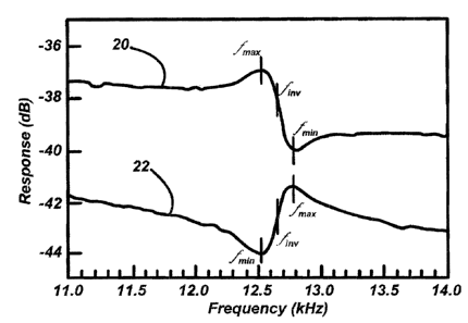
Figure 2a is a graph of two acoustic response spectra for the 1L acoustic mode
as
observed for the two locations shown in Figure 2b, which is a schematic of an
arc
discharge tube in a vertical orientation.
Figure 3 is a graph of several acoustic response spectra at different
modulation
amplitudes for the 1 L acoustic mode as observed at the upper region of the
discharge
tube.
Description of Preferred Embodiments
In a preferred embodiment, the present invention is a method of operating a
discharge lamp that uses two power frequency components.. The first component
is a
sweep over a range of frequencies whose purpose is to straighten and center
the arc in the
discharge cavity. The swept frequencies are preferably over or near the second
azimuthal
(2A) resonance frequency, but there can be a relatively wide range of sweep
frequencies
for particular types of waveforms. The 2A frequency is between the first
azimuthal (1 A)
and first radial (1R) acoustic mode frequencies. It is noted here that not all
arc discharge
tubes require arc straightening to stabilize and center the are. Therefore,
while it is
preferred to include an arc-straightening frequency component, it is not
always necessary.
The second component is an excitation of the first longitudinal (1 L)
resonance
mode, but in a way that is different from the usual way of matching a
resonance.
Usually, the excitation of a resonance is strongest when the applied frequency
matches a
resonance peak frequency, falling off as the excitation frequency is detuned
to higher or
lower frequencies. The "center" frequency corresponds to the peak in
resonance. The
-6-
CA 02476525 2004-08-04
inventor has found that there are two different responses when the excitation
frequency is
near but separated from the center of the 1 L resonance response in the
acoustic spectrum.
By way of further explanation, and with reference to the first longitudinal (1
L)
acoustic mode shown in Figure 1, for a cylindrical cavity with an isothermal
temperature
distribution, the 1L mode is the lowest frequency resonance mode, with the
wavelength
of the standing pressure wave being twice the length of the cylinder. The
resulting
pressure distribution is axially asymmetric, with the perturbation at one end
of the arc
discharge tube being opposite in sign from the other end. Due to this
asymmetry, the 1 L
mode is not expected to be effectively excited in an arc tube that is axially
symmetric
with respect to arc position and vapor distribution. However, when the arc
tube 5 is
operated vertically as illustrated in Figure 2b, an asymmetric vapor
distribution arises in
the substantially cylindrical discharge cavity 17 due to segregation. A
spatially resolved
acoustic resonance spectrum (Figure 2a) can be obtained by placing a
photodiode at the
projected image of the operating are tube, preferably towards ends of the arc
tube where
the pressure perturbation and consequent light fluctuation are enhanced
(observation
points 10 and 12 in Figure 2b). A preferred location to observe the acoustic
resonance
spectrum is at a point which is approximately one-quarter of the length of the
cavity away
from an end of the discharge cavity. It is not desirable to observe the
response directly at
the electrodes 15 because of the "hot spots" which occur at the point of arc
attachment. It
is also not desirable to observe the response too close to the center
(lengthwise) of the arc
tube as the amplitude of the response is minimal at the center.
Instrumentation that
measures the acoustic resonance spectrum of the are tube is known. (See, e.g.,
J. Olsen
and W.P. Moskowitz, "Optical Measurement of Acoustic Resonance Frequencies in
HID
-7-
CA 02476525 2004-08-04
Lamps," Proceedings of the IEEE Industrial Applications Society Annual
Meeting, New
Orleans, LA, Oct. 1997) The frequency spectrum of the light output, as
detected by a
photodiode placed at the image plane of a projection of the arc tube, is
normalized by the
frequency spectrum of the input power in order to determine the acoustic
response of the
arc tube. A small amount of noise over an appropriate bandwidth is added to
the input
power in order to obtain an acoustic response over a desired frequency range.
A vector
signal analyzer such as the HP89410A (Hewlett-Packard) can be used to
facilitate the
measurement.
With the arc tube in Figure 2b oriented vertically and a photodiode positioned
to
observe an acoustic response at point 10 at an upper region of the arc tube,
the input
lamp power is modulated with at least one arc-straightening frequency to
produce a stable
discharge. A further frequency component is then added to the modulated lamp
power as
described above and the acoustic response spectrum is observed. Preferably,
the
spectrum extends about 2kHz on either side of the 1 L resonance response. More
generally, the spectrum includes a frequency range of about 20% on either
side of the
1 L resonance response. At the upper region of the arc tube, acoustic response
spectrum
is observed as shown in Figure 2a wherein the 1 L resonance response appears
centered about a frequency of about 12.6 kHz. The 1 L feature in acoustic
response
spectrum 20 has a maximum response at a first frequency, f max, and a minimum
response
20 at a second frequency, f,,,;,, with an inversion occuring at a third
frequency, f;,,,,, which is
between fmax and fmjn, In this case, fmaxand fm;n are separated by about 300
Hz. As the
asymmetry in the are tube increases over time, f max, f min, f 11 , tend to
shift to higher
frequencies. Moreover, it is important to note that fmax occurs at a frequency
below f;nV
-8-
CA 02476525 2004-08-04
and fmin occurs at a frequency above f inv. The importance of the relative
positions of
,f max, fmin, and f inv will be made clear below.
When the photodiode is positioned at point 12 at a lower region of the arc
tube,
the observed 1 L acoustic response is still centered at about 12.6 kHz however
the
acoustic response spectrum 22 appears as the inverse of the acoustic response
spectrum
20 observed at the upper region. In this case, f max occurs at a frequency
which is greater
than f inv and ,fmin occurs at a frequency which is less than f;nv. The
position of f inv
remains essentially the same and f max and fmin are still separated by about
300Hz.
Excitation of the 1 L resonance can induce different directions of flow in the
arc
tube, and the behavior depends on whether the applied excitation frequency is
above or
below f inv. More importantly, the segregation behavior may be dramatically
different
depending upon the applied excitation frequency and the relative positions of
f max, fmin,
and f inv in the arc tube s acoustic response spectrum. In an arc discharge
tube whose
electrodes extend the same length into the discharge cavity as shown in Figure
2b, the
acoustic response spectrum observed at an upper region of the arc tube, when
the arc tube
is operated in a vertical orientation, is similar to spectrum 20 in Figure 2a
wherein f max
occurs at a frequency below f inv and fmin occurs at a frequency above f inv.
If the 1 L
excitation frequency is selected to be below f inv, e.g., at around 12 kHz,
there is an
improved mixing of the vapor phase species and decreased segregation, as
indicated by
reduced color separation of the arc. The 1 L response in the acoustic spectrum
also
decreases in amplitude as the 1 L resonance amplitude is increased, indicating
that the
lamp is becoming more symmetric (e.g., as shown in Figure 3). In contrast, if
the applied
excitation frequency is above fine, e.g., at about 13 kHz, the arc tube tends
to segregate
-9-
CA 02476525 2004-08-04
further, with extreme color separation of the arc. Segregation increases until
f inv, which
is shifting higher with segregation, becomes equal to the applied excitation
frequency.
There a stable level of segregation is reached. If the lamp were to segregate
further, f inv
would be higher than the applied excitation frequency, which would tend to
decrease
segregation.
With careful selection of the applied excitation frequency, the 1L resonance
can
be effectively used to reduce segregation in the arc discharge tube. For arc
tubes which
exhibit at an upper region, when operated vertically, an acoustic response
spectrum
wherein fmax<f inv, the applied excitation frequency, f eXC, should be less
than f in,,. For
most arc tubes exhibiting this behavior, the range of useful excitation
frequencies will
extend about 1-2 kHz below f inv, with the optimal effect being obtained when
feXC is
approximately equal to f m~X. Hence, it is preferred that fn,,-2kHz _< f exe <
f inv. More
generally, it preferred that the applied excitation frequency be within 20% of
fin,,,
(fin,,-0.2 * f inv <_ f eXC < f inv), and even more preferred within 10% of
fin,,,
(f inv-0.1 *f inv < fen < f inv)=
Lamp Sample: JA013
The method of this invention was tested on a lamp having the following
characteristics.
Arc tube shape: The inner cavity is substantially cylindrical with spherical
end
bells. The arc tube has an inner length of about 23 mm and a 3.7 mm diameter
at the
center of the arc tube that tapers slightly towards the ends.
Arc tube contents: 10 mg of a metal halide salt mixture (Nal: DyI3: Ho13:
TM13:
TII in a 6: 1: 1: 1: 0.75 molar ratio), 2 bar Xe.
-10-
CA 02476525 2004-08-04
Acoustic response: f,,,a, at 12.7 kHz, f i,,,, at 12.85 kHz.
In preparation for the tests, the lamp was first run on a square wave with a
132-
145 kHz ripple (for straightening the arc), vertically base up, until most of
the salt had
accumulated at the bottom (dome) end of the arc tube. In this situation, the
tendency of
the vapor to mix or segregate is quickly detectable through changes in are
color, without
having to wait for the salt to redistribute. A 12 kHz excitation frequency was
then added
to the ripple, mixing the lamp vapor and reducing the color separation which
had begun
to appear.
With reference again to Figure 3, acoustic spectra in. the 1 L region were
observed
at an upper region of the arc tube and were recorded as a function of 12 kHz
excitation
amplitude (relative amplitude from 0.15 to 0.03), keeping the power constant
at 70W by
adjusting the square wave amplitude. As the amplitude is decreased, the vapor
begins to
segregate, the 1 L feature in the acoustic spectrum becomes more pronounced,
and the
lamp voltage also decreases.
Increasing the amplitude restores the lamp to stable vertical operation. This
ability to recover from a segregated state is not seen when using some other
acoustic
resonance modes, which are mainly useful for preventing segregation when
applied to a
lamp which is not yet segregated. Because the 1 L mode is asymmetric, it can
be readily
excited in a segregated lamp whereas axially symmetric modes such as the
second and
fourth longitudinal modes may not be readily excited.
An amplitude modulation method of selectively applying the 1 L resonance
excitation frequency was also tested successfully on lamp JA013. In this case,
a sine
wave swept in frequency from 63-71 kHz (126-142 kHz power) was used to power
and
-11-
CA 02476525 2004-08-04
straighten the arc. The amplitude of the sine wave was then modulated at 12
kHz to
allow vertical operation. A modulation index of 0.1 is sufficient for
preventing
segregation in the short term. A preferred modulation index is from 0.1 to
0.15.
The 1 L resonance frequency can be applied while starting the lamp in vertical
orientation. As the lamp warms up, the 1 L mode is "captured" and the lamp
eventually
reaches a non-segregated state of operation.
Another advantage of using the 1 L resonance frequency is that no salt rings
accumulate on the hot cylindrical part of the arc tube. This may help to
prevent corrosion
of the arc tube wall.
A potential drawback in using these frequencies is that they are low, being
within
the audible range in the case of some lamps. In shorter lamps, the 1 L
resonance is higher,
at about 20 kHz, and using a 1 L resonance frequency according to the method
of this
invention has been successfully used to prevent segregation. in these lamps.
In addition to
reducing the length of the arc tube, another way of increasing the 1 L
resonance frequency
(and all other frequencies) is to decrease the average molecular mass of the
buffer gas.
For this reason, fill gas compositions with lighter gases such as argon can be
substituted
for xenon.
In a preferred embodiment, the 1 L excitation frequency, fexc, may be a fixed
frequency, or a frequency sweep through a range of frequencies within the
range dictated
by the acoustic response spectrum as explained above. The frequency sweep
through the
arc-straightening frequency range may be at a sweep rate of 100-1,000 Hz.
As noted above, two power frequency components are used in the present
invention. There are generally multiple kinds of voltage waveforms that can
produce the
-12-
CA 02476525 2004-08-04
desired power frequency components in the operating lamp. The inventor has
used the
following types of voltage waveforms to get the two power frequency components
A and
B, where A is the arc-straightening sweep over a range of frequencies and B is
the 1 L
resonance excitation frequency, f c: (1) square wave with additive ripple: a
low
frequency(about 20-500 Hz) switched-DC waveform with a high frequency ripple
superimposed, where the ripple is obtained by adding two sine waves with
frequencies A
and B; (2) square wave with sequential ripple: a low frequency(about 20-500
Hz)
switched-DC waveform with a high frequency ripple superimposed, where the
ripple is a
sine wave which alternates between frequency A and frequency B; and (3)
amplitude
modulation (AM): a sine wave at frequency (A/2) is amplitude modulated at
frequency B.
Other possibilities are (4) direct drive sequential: a sine wave in which the
frequency
alternates between (A/2) and (B/2); (5) direct drive additive: a sum of two
sine waves at
frequencies (A/2) and (B/2); (6) other periodic waves besides sine waves; and
(7)
additive or amplitude modulated waveforms in which the interference bands are
used (for
example, when two frequencies C and D are combined, there are often power
components at C+D, C-D, 2C+D, 2C-D, etc.).
By way of example, and with reference to Tables 1-3 below, the inventor has
operated different lamp types using waveform type (2) above. Segregation was
reduced
during vertical operation. The frequency of the switched-DC (square wave)
voltage
waveform was 400 Hz. The sweep rate for frequency A was 1 kHz. The gate times
indicate the time spent at each frequency as the frequency alternates between
A and B.
Lamp ID: JH062
Arc tube shape: The inner cavity is approximately cylindrical with spherical
end
-13-
CA 02476525 2004-08-04
bells. The arc tube has an inner length of about 23 mm and a 3.7 mm diameter
at the
center that tapers slightly towards the ends.
Arc tube contents: 1.8 mg Nal, 0.77 mg CeI3, 1.8 mg DyI3, 0.89 mg Ca12, 0.21
mg
TlI, 2 bar Xe.
Electrical: At 65 W, voltage is about 54 V and current is about 1.2 A.
Acoustic response: f,,,ax at 12.95 kHz, f;, at 13.15 kHz.
Some parameters that worked are given in Table 1 below:
Table 1
Freq A Gate A Ampl A Freq B Gate B Ampl B
130-150 kHz 1.8 ms 30 vpp 12.9 kHz 0.7 ms 50 vpp
130-150 kHz 1.5 ms 30 vpp 12.9 kHz 1.0 ms 33 vpp
130-150 kHz 1.3 ms 30 vpp 12.9 kHz 1.2 ms 30 vpp
130-150 kHz 1.0 ms 30 vpp 12.9 kHz 1.5 ms 24 vpp
130-150 kHz 0.5 ms 30 vpp 12.9 kHz 2.5 ms 20 vpp
130-150 kHz 1.5 ms 30 vpp 12.7 kHz 1.0 ms 30 vpp
130-150 kHz 1.5ms 30vpp 12.2 kHz 1.0ms 32 vpp
130-150 kHz 1.5 ms 30 vpp 11.7 kHz 1.0 ms 37 vpp
130-150 kHz 1.5ms 30vpp 11.2 kHz 1.0ms 39vpp
Lamp ID: LA007
Arc tube shape: Approximately cylindrical with spherical ends; 5.2 mm inner
diameter at the center that tapers slightly towards ends; and inner length
about 30.5 mm.
-14-
CA 02476525 2004-08-04
Arc tube contents: 15 mg of a metal halide salt mixture (Nal: Dy13: Ho13:
TmI3:
TlI in a 6: 1: 1: 1: 0.75 molar ratio), 1 bar Xe.
Electrical: Lamp voltage was 90-95 V.
Acoustic response: f;,,, estimated at 8.9 kHz.
Some parameters that worked are given in Table 2:
Table 2
FreqA Gate A Ampl A Freq B Gate B Ampl B
85-100 kHz 1.5 ms 70 vpp 8.8 kHz 1.0 ms 70 vpp
Lamp ID: CAl
Arc tube shape: Cylindrical; 3.2 mm i.d.; and 22.4 mm inner length.
Arc tube contents: 3 mg of a metal halide salt mixture (Nal: DyI3: HoI3: TmI3:
Tll
in a 6: 1: 1: 1: 0.75 molar ratio), 2 bar Xe.
Electrical: At 50 W, voltage is about 40 V and current is about 1.25 A.
Acoustic response: fmax at 13-14 kHz, f;,,,, at 14.4-14.6 kHz.
Some parameters that worked are given in Table 3:
-15-
CA 02476525 2004-08-04
Table 3
Freq A Gate A Ampl A Freq B Gate B Ampl B
155-175 kHz 1.5 ms 27 vpp 14 kHz 1.0 ms 27 vpp
155-175 kHz 1.5 ms 27 vpp 13.4 kHz 1.0 ms 30 vpp
155-175 kHz 1.5 ms 27 vpp 12.4 kHz 1.0 ms 30 vpp
155-175 kHz 1.5 ms 27 vpp 11.4 kHz 1.0 ms 30 vpp
155-175 kHz 1.5 ms 27 vpp 10.4 kHz 1.0 ms 35 vpp
155-175 kHz 1.5 ms 27 vpp 9.4 kHz 1.0 ms 38 vpp
While embodiments of the present invention have been described in the
foregoing
specification and drawings, it is to be understood that the present invention
is defined by
the following claims when read in light of the specification and drawings.
-16-