Note: Descriptions are shown in the official language in which they were submitted.
CA 02476554 2004-08-25
WO 03/056175 PCT/US02/40073
1
Description
ENERGY TRANSFER ASSEMBLY
BACKGROUND OF THE INVENTION
The present invention relates to an improved assembly to
facilitate the transfer of energy, specifically, the transfer of
the mechanical or kinetic energy present in a moving vehicle into
usable electrical power. This is accomplished utilizing a
plurality of vehicles traveling on a substantially closed loop
track system, wherein the track is structured to include impact
members to absorb the kinetic energy from the vehicles, and lever
and gear assemblies to transfer the kinetic energy to a power
generator, such as a conventional electrical power generator.
Description of the Related Art
With the drastic and continued increase in world population,
and the attendant increases in industrialization, there is an ever
increasing demand for conventional fuels, such as fossil fuels.
The result is the diminishment of the world fossil fuel supply
resulting in shortages and continuously rising prices which have
occurred in numerous industrialized nations. Although such
conventional fuels are still the primary source of energy for
driving conventional power generating assemblies, such as
electrical power generators, there is an ever increasing demand
for alternative energy sources which would effectively reduce the
demand for fossil fuel and which would also be less detrimental
to the environment than conventional.
Among the recognized alternative energy sources are nuclear
energy and solar energy. Nuclear energy, while effective for
driving conventional electrical power generators and similar power
generating devices, is known to be dangerous and extremely
expensive. As a result of recent accidents resulting in death to
inhabitants in the vicinity surrounding nuclear power facilities,
nuclear energy has become a less and less desirable alternative.
Solar energy, on the other hand, while considered to be a
clean and safe alternative source of energy, has recognized
CA 02476554 2004-08-25
WO 03/056175 PCT/US02/40073
2
disadvantages related to efficiency. As a result, utilization of
solar energy has not been generally accepted for use in industrial
applications or wide spread, high capacity electrical power
generation.
As such, there is still an increasing demand for an alternate
energy source which is efficient for driving relatively large
scale, high capacity electrical generators and similar devices,
and is capable of providing electrical power for both domestic and
industrial facilities in densely populated areas. One area which
has generally been overlooked is the utilization of mechanical
energy, specifically, the kinetic energy available in moving
vehicles, such as moving trains, which are plentiful throughout
the United States as well as most industrialized countries of the
world and are capable of being used to drive electrical generators
or similar power generating devices, thereby effectively
transferring their kinetic energy into usable electrical power,
without the disadvantages and threats to public health and safety
or to the environment, which are inherent in conventional power
generating assemblies.
Summary of the Invention
The present invention is directed to an improved energy
transfer assembly which allows the efficient transfer of
mechanical or kinetic energy into electrical energy. The improved
energy transfer assembly utilizes a generally circular track
system preferably comprising a substantially closed loop
configuration, along which one or more wheeled vehicles may
travel, such as conventional locomotive engines and railcars. At
least one pair of impact members, each including a first impact
member and a second impact member, are operatively positioned
along the track system, and each of the impact members are
alternately movable between an extended position and a retracted
position upon contact with a flange of a wheel of the vehicles)
traveling along the track system. In one embodiment of the
present invention, a plurality of pairs of impact members are
operatively positioned along the track system.
CA 02476554 2004-08-25
WO 03/056175 PCT/US02/40073
3
The present invention further incorporates one or more lever
assemblies, each interconnected to a pair of impact members such
that the impact plates are in driving engagement with the
corresponding lever assembly. Each lever assembly is subsequently
interconnected with and operates in cooperative engagement with
a corresponding gear assembly. The cooperative association
between each lever assembly and the corresponding gear assembly
is structured such that a drive arm, which movably interconnects
the lever assembly to a primary auxiliary gear of the gear
assembly, causes movement of the primary auxiliary gear.
In one embodiment of the present invention, each gear
assembly includes a plurality of auxiliary gears each associated
with a corresponding drive gear. In addition, each gear assembly
includes a corresponding transfer drive gear, which is structured
to effect the movement of a rotational component of a power
generator. As a result of the movement of the rotational
component, each power generator of the present invention produces
usable electrical power, which may be transferred to any one of
a number of remote locations via a plurality of conductor cables.
The continuous movement of the locomotives and railcars
around the circular track system of the present invention may
transfer enough kinetic energy to power potentially hundreds of
large electrical generators, for example, 1,000 kilowatts, each
of which can provide electrical energy to many inhabitants in
numerous cities either at a very low cost, or perhaps, at no cost .
These and other objects, features and advantages of the
present invention will become more clear when the drawings as well
as the detailed description are taken into consideration.
Brief Description of the Drawings
For a fuller understanding of the nature of the present
invention, reference should be had to the following detailed
description taken in connection with the accompanying drawings in
which:
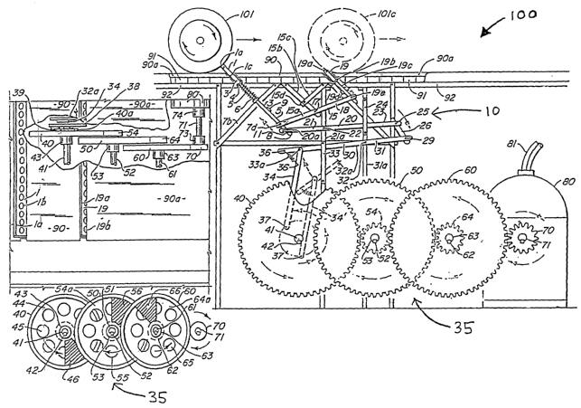
Figure 1 is a top view in partial cutaway of a gear assembly
and impact members of the present invention.
CA 02476554 2004-08-25
WO 03/056175 PCT/US02/40073
4
Figure 2 is a side view of a portion of the gear assembly of
the present invention.
Figure 3 is a side view and partial phantom of operative
components of the present invention as a flange on a wheel of a
vehicle contact the impact members associated therewith.
Figure 4 is a side view similar to the embodiment of Figure
3 wherein the flange of the wheel of the vehicle contacts
different impact members at different locations.
Figure 5 is a front view in partial section and cutaway
showing the operation of various components of one preferred
,embodiment of the present invention.
Figure 6 is a side view showing details of certain components
of the gear assembly of the present invention taken along line 6-6
of Figure 7.
Figure 7 is an end view taken along line 7-7 of Figure 6.
Figure 8 is a sectional view similar of that of Figure 6
showing different positions of the various components thereof.
Figure 9 is a sectional view in partial cutaway showing
details of each of the impact members taken along line 9-9 of
Figure 5.
Figure 10 is a front view of another preferred embodiment of
the present invention utilizing a locomotive engines) and/or
railcars as the moving vehicle shown in partial section and
cutaway demonstrating the operation of various components of the
present invention in association with the vehicle.
Figure 11 is a schematic representation of one preferred
embodiment of a generally circular, substantially closed loop
railway track system of the present invention illustrating the
relative locations of a plurality of pairs of grooves.
Figure 12 is a side view of the pair of grooves in a portion
of one of the rails of the railway track system along line 12-12
of Figure 11.
Like reference numerals refer to like parts throughout the
several views of the drawings.
CA 02476554 2004-08-25
WO 03/056175 PCT/US02/40073
Detailed Description of the Preferred Embodiment
While this invention is susceptible of embodiment in many
different forms, there is shown in the drawings and will herein
be described in further detail, including specific dimensional
5 features of at least one most preferred embodiment, with the
understanding that the present disclosure is to be considered as
an exemplification of the present invention and is not intended
to limit the scope of embodiments encompassed by the present
invention to the specific embodiments described and illustrated
herein.
The present invention is directed to an improved energy
transfer assembly, generally shown as 100 throughout the Figures.
The assembly 100 includes a track system 110, which preferably has
a generally circular closed loop configuration, as illustrated in
Figure 11, upon which one or more wheeled vehicles travel. In one
preferred embodiment of the present invention, the track system
110 includes parallel rails 112, including a plurality of inner
rails 114 and a plurality of outer rails 116, such as are commonly
used for commercial locomotive engines and the various railcars
they transport.
As illustrated in Figures 11 and 12, each of the plurality
of inner rails 114 and outer rails 116 of the present invention
include at least one, but preferably a plurality of pairs of
grooves 118, which are each oriented at a predetermined angle of
preferably 45 degrees into the direction of travel of the wheels
101 of the vehicles) traveling along the track system 110, in at
least one preferred embodiment of the present invention. As
illustrated in Figure 11, each corresponding pair of grooves 118
in the inner rails 114 and the outer rails 116 are aligned such
that a line drawn from the center of the circular closed loop
configuration of the track system 110 will intersect each
corresponding pair of grooves 118 along the track system 110.
Each of the plurality of pairs of grooves 118 are separated
by pavement plates, including a short pavement plate 90 and a long
pavement plate 90a. These pavement plates 90 and 90a, as well as
Certain other components of the present invention, are supported
CA 02476554 2004-08-25
WO 03/056175 PCT/US02/40073
6
by a supporting plate 91 and supporting beam 92. Other
conventional structures may be included such as a concrete curb
and/or a gutter.
A preferred embodiment of the present invention includes a
generally circular, substantially closed loop railway track system
110 which is preferably structured to facilitate the operation of
four locomotive engines each pulling nineteen railcars, and two
locomotive engines each pulling eighteen railcars. Preferably,
each of the railcars is 55 feet in length, with each of the
nineteen railcars having a load weight of two tons, while each of
the eighteen railcars has a load weight of three tons. The
locomotive engines are electrically powered and will at least
initially receive the electrical power they require to operate
from an external power source, preferably from a system of
overhead wires. However, once the assembly is operational, the
locomotive engines will receive their required electrical power
from the power generated by the assembly 100. The trains will
operate one behind the other at the same speed, preferably
controlled by remote control, and at a distance of approximately
2 0 4 0 feet f rom one another .
As previously indicated, at least one embodiment of the
present invention utilizes parallel rails 112. These parallel
rails 112 have a preferred gauge of 4 feet and 8.5 inches between
the inner rails 114 and the outer rails 116. Preferably, the
outer rails 116 form a circle having a circumference of
approximately 6,750 feet, thereby requiring approximately 150
rails, each preferably being approximately 45 feet long and 6
inches high. Further, each outer rail 116 preferably includes at
least two pairs of grooves 118 in the inside face of the rail,
each being 1.5 inches long and 5/8 of an inch deep. The outside
face of each outer rail 116 may include a fortifying support at
each location which coincides with each pair of grooves 118 in the
inside face of each rail 116. Each of the grooves in each pair
of grooves 118 preferably has an inclination of 45 degrees facing
into the direction of travel of the oncoming trains, with the
groove of each pair of grooves 118 closest to the oncoming train
CA 02476554 2004-08-25
WO 03/056175 PCT/US02/40073
7
being a leading groove 118a and while the other is a trailing
groove 118b. The separation between each pair of grooves 118
along the path of each outer rail 116 may be approximately 20 feet
and 3 inches, and the separation between each corresponding
leading groove 118a and trailing groove 118b is preferably about
2 feet. The pair of grooves 118 near either end of each outer
rail 116 are preferably maintained a distance of approximately 10
feet and 1.5 inches from either end of each rail 116.
With respect to the inner rails 114, they preferably form a
circle having a circumference of 6,720 feet thereby requiring
approximately 150 inner rails 114, each preferably being
approximately 44 feet and 9.6 inches long and 6 inches high. Each
inner rail 114 also preferably has at least two pairs of grooves
118 in the inside face of each inner rail 114, with the separation
between the leading groove 118a and the trailing groove 118b in
each pair of grooves 118 also being approximately 1 foot and 11-
5/8 inches. The separation between the pairs of grooves 118 along
the inner rails 114 is preferably 20 feet and 1-7/8 inches, and
the pairs of grooves 118 near either end of each inner rail 114
are also maintained a distance of approximately 10 feet and 1 inch
from each end.
Each inner rail 114 arid - outer rail- -116 - is- preferably
constructed of steel and has a curvature of 2.4 degrees. The
generally circular closed loop railway track system 110 is
preferably constructed at a height of approximately 10.5 feet
above grade to provide enough space below the tracks for the other
components of the assembly 100 of the present invention.
Each railcar utilized by the present invention preferably has
five pairs of wheels 101, each wheel 101 being 34 inches in
diameter and including a flange 102. Each flange 102 is
preferably 2 inches wide to provide sufficient contact surface
area with a plurality of pairs of impact members, each having a
first impact member 1 and a second impact member 19, operatively
positioned around the track system 110 in each of the
corresponding pair of leading grooves 118a and trailing grooves
118b, respectively, in each of the inner rails 114 and outer rails
CA 02476554 2004-08-25
WO 03/056175 PCT/US02/40073
8
116. The separation between each pair of wheels 101 is preferably
11 feet, and the wheels 101 near each end of each railcar are
maintained a distance of 5.5 feet from either end, such that each
pair of wheels 101 of each railcar that operates on the generally
circular closed loop railway track system 110 are preferably
maintained at a distance of 11 feet from one another. The
distance between each pair of wheels 101 of each railcar operating
on the generally circular closed loop railway track system 110 is
significant in relation to the distance between each pair of
grooves 118 in the parallel rails 112 in order to assure that the
wheels 101 of each railcar do not contact both the first and
second impact members 1 and 19 of any pair of impact members at
the same time. The trains each operate at the same speed,
preferably 30 miles per hour (mph) , and maintain a distance of
approximately 40 feet between one another. At higher speeds, the
available kinetic energy is multiplied several times, thereby
providing an increase in the amount of electrical power generated.
As indicated above, the present invention comprises a
plurality of pairs of impacts members, each having first and
second impact members 1 and 19 operatively positioned in spaced
apart relation to one another along the track system 110. Each
impact member 1 and 19 is preferably 4 feet and 9 inches Long, 4
inches high, and 1 inch thick, constructed of a light weight yet
hard material, and having a plate-like configuration with
oppositely disposed smooth surfaces. Further, each first and
second impact member 1 and 19 includes a plurality of first and
second leading rollers, la and 19a, respectively, formed along the
leading longitudinal edge of each member, thus positioned to
engage the flange 102 of one of the wheels 101, as noted above.
Further, each first and second impact member 1 and 19 is
preferably positioned at an approximately 45 degree angle to an
outer surface of the track system 110 and into the direction which
the wheels 101 of the trains) travel. This positions each first
and second leading roller 1a and 19a in a substantially
perpendicular relation to the oncoming surface of the flange 102
on each wheel 101, to achieve maximum efficiency of operation of
CA 02476554 2004-08-25
WO 03/056175 PCT/US02/40073
9
the assembly of the present invention upon contact.
Each pair of impact members 1 and 19 are at least partially
interconnected to one another by a plurality of minor action
levers 15, preferably three in number with each being
approximately 21 inches long, 3 inches wide, and 3/4 of an inch
thick, and constructed of steel. A short arm 15a of each minor
action lever 15 is preferably 10.5 inches long while a long arm
18 of each minor action lever 15 is preferably 10.75 inches long
having an approximately 2.5 inch wide groove in one end. Each
minor lever short arm 15a is preferably interconnected to the
first impact member 1 by a corresponding one of a plurality of
first minor impact bars 5 which are either 23 or 32 inches long
and 7/8 of an inch in diameter, with each also being constructed
of steel. The first minor impact bar 5 which is generally
positioned near the middle of the first impact member 1 is
preferably 32 inches long, while the remaining first minor impact
bars 5 are preferably 23 inches long. Each of the first minor
action levers 15 are interconnected to one of a plurality of
corresponding first major impact bars 8, which ultimately
interconnect with one of a plurality of first major action levers
20, as discussed in further detail hereinafter.
Further, each of the plurality of minor action levers 15 is-
preferably supported on a corresponding one of a plurality of
second long support beams 15b, which are interconnected to one of
a plurality of corresponding second short support beams 15c. The
second long and short support beams 15b and 15c are preferably
oriented at opposing 45 degree angles from the underside of the
track system 110 and interconnected by one of a plurality of
second f fixed al ignment bars 15d . In one pref erred embodiment , one
of a plurality first fulcrums 17 movably interconnects each minor
action lever 15 to a corresponding one of the plurality of second
long support beams 15b. Each of the plurality of minor lever long
arms 18 is preferably interconnected to a corresponding one of a
plurality of second minor impact bars 19c by one of a plurality
of second minor lever pivotal connectors 19e, which allow each
first minor action lever 15 to be further positionable based on
CA 02476554 2004-08-25
WO 03/056175 PCT/US02/40073
the movement of each second impact member 19.
Each of the first and second impact members 1 and 19 are
disposed to be movable between an extended position, as
illustrated by the position of the first impact member 1 in Figure
5 3, and a retracted position, as illustrated by the position of the
second impact member 19 in Figure 3. In a preferred embodiment
of the present invention, the extended position is at least
partially defined by a portion of the first or second impact
member 1 and 19 extending outwardly from an outer surface of the
10 rails 112.
It should be apparent from Figures 3 and 4 that as the flange
102 of one of the wheels 101 engages each first or second impact
member 1 and 19, the impact member will be forced from its
extended position to the retracted position, while the other of
the first or second impact member 1 and 19 not contacted by the
flange 102 will be forced into its opposite, extended position.
For example, when the flange 102 contacts the first impact member
1, it will of course be forced downwardly into its retracted
position from its extended position, as illustrated by the
position of the wheel 101 and the first impact member 1 with wheel
101 at position 101a, in Figure 4. Further, upon the flange 102
of the wheel 101 contacting the impact member 1 arid--forcing it
into its retracted position, the second impact member 19 will be
forced upwardly into its extended position, also as illustrated
in Figure 4. Since the travel of the train will be as indicated
by the directional arrows in Figure 4, the second impact member
19 will be subsequently contacted by the flange 102 of the wheel
101, as represented by the position of the wheel at lOlb. This
will then force the second impact member 19 into its retracted
position and, accordingly, due to the interconnection of the
impact members 1 and 19 by the plurality of minor action levers
15, will force the first impact member 1 back into its extended
position. In the extended position, each of the first and second
impact members 1 and 19 are ready for contact with the flange 102
of the next oncoming wheel 101.
For purposes of clarity, Figure 4 represents the various
CA 02476554 2004-08-25
WO 03/056175 PCT/US02/40073
11
positions of the wheel 101 as it approaches, and as its flange 102
subsequently contacts, each of the first and second impact members
1 and 19. For example, the wheel 101 in a first position
illustrates the wheel 101 upon immediate impact of its flange 102
with a first leading roller 1a mounted~on a leading edge of the
first impact member 1 (see Figure 9). The position of the wheel
101 at 101a illustrates the first impact member 1 being driven
into its retracted position against one of a plurality of
compression springs 6. Position 101b shows the position of the
wheel 101 immediately upon its flange 102 contacting the second
leading roller 19a connected to a leading edge of the second
impact member 19. Finally, the position of the wheel 101 at 101c
in Figure 3 illustrates the second impact member 19 being driven
into its retracted position.
Other structural features of the first and second impact
members 1 and 19 preferably include first and second fixed
members, 1c and 19c, respectively, which are provided along with
two lateral alignment bars 2 to maintain the impact members 1 and
19 in position in each corresponding pair of grooves 118. The
plurality of first minor impact bars 5 preferably serve as an
interconnection between a movable spring compression plate 4 and
each minor lever short arm 15a . In at least - one ercibodiment of the - -
present invention, the plurality of compression springs 6 serve
to bias the first impact member 1 into its extended position. A
fixed spring compression plate 7, including a plurality of
compression plate apertures 7a, preferably five in number, is
connected to the underside of the track system 110 by two first
long support beams 7b, which are preferably disposed at a 45
degree angle from the underside of the track system 110.
A preferred embodiment of the assembly 100 of the present
invention includes a lever assembly, generally shown as 10
throughout the Figures. The lever assembly 10 includes a
plurality of linkage members which serve to provide a movable
interconnection between each pair of first and second impact
members 1 and 19 and a corresponding gear assembly, generally
shown as 35.
CA 02476554 2004-08-25
WO 03/056175 PCT/US02/40073
12
As previously noted, the assembly 100 of at least one
embodiment of the present invention includes a plurality of first
maj or impact bars 8 each movably interconnected to a corresponding
one of the plurality of first major action levers 20. Each first
major impact bar 8 is movably interconnected to the corresponding
first major action lever 20 by a lever slot connector 20a which
is positioned through lever slot 11. In addition, each first
major impact bar 8 is preferably movably interconnected to one end
of a corresponding one of the plurality of minor action levers 15
by way of a minor lever pivotal connector 7d. This provides a
movable, preferably pivotal, interconnection between each pair of
first and second impact members 1 and 19 to each corresponding
first major action lever 20.
Each first major action lever 20 is preferably movably
supported on a first vertical support beam 21a by a corresponding
one of a plurality of second fulcrums 22. A first guide plate 24
is provided for each first major action lever long arm 23, and a
corresponding one of a plurality of auxiliary levers 26 is
preferably movably connected to one end of each first major action
lever 20 by a first auxiliary pivotal connector 25.
A preferred embodiment of the assembly 100 of the present
invention further- includes -a- plurality of -second maj-or-actiori
levers 30 each being at least partially and movably supported on
a corresponding one of a plurality a second vertical support beam
31a by one of a plurality of third fulcrums 32. Further, a second
guide plate 33 is provided for a second major lever long arm 32a
on each of the plurality of second major action levers 30. Each
second major action lever 30 also includes a second major lever
short arm 31 which is preferably movably interconnected to a
corresponding one of the plurality of auxiliary levers 26 by a
second auxiliary pivotal connector 29.
The opposite end of each of the plurality of second major
action levers 30 is preferably movably interconnected to a
Corresponding one of a plurality of drive arms 34. In a preferred
embodiment, each drive arm 34 has an elongated configuration with
one end interconnected to the end of the long arm 32a of the
CA 02476554 2004-08-25
WO 03/056175 PCT/US02/40073
13
corresponding second major action lever 30 by a first drive arm
pivotal connector 33a, and an opposite end of each drive arm 34
interconnected to a corresponding one of a plurality of auxiliary
gears 38 by a second drive arm pivotal connector 37.
Additionally, each drive arm 34 is preferably interconnected to
its corresponding second major action lever 30 by one of a
plurality of drive arm springs 36, which serve to bias each drive
arm 34 into an upstroke orientation, as discussed in further
detail below. Each drive arm spring 36 is preferably 2.5 inches
long and 3/8 of an inch in diameter, and serves to at least
partially pull the drive arm 34 through the last third of a cycle
along a circular path of rotation of a corresponding one of a
plurality of primary auxiliary gears 38, thereby maintaining the
gear 38 in the best position to rotate forward each time the
flange 102 of one of the wheels 101 contacts the corresponding
pair of first and second impact members 1 and 19. Preferably, a
delay of a fraction of a second occurs between the contact of the
flange 102 with the first impact member 1 and, subsequently, the
second impact member 19,,and in this fraction of a second, each
drive arm spring 36 assists in positioning its corresponding
primary auxiliary gear 38 into an optimum position to rotate
forward v~hen a subsequent -flange-102 contact's the corresponding
first and second impact members 1 and 19.
The assembly 100 of the present invention further preferably
includes a pawl and ratchet assembly including a spring biased
pawl 39 mounted on each of the plurality of primary auxiliary
gears 38 about a pawl pivot point 39a, which allows the pawl 39
to rotate with the gear 38, and about the pivot point 39a, as
illustrated in Figures 6, 7, and 8. Each spring biased pawl 39
cooperatively associates with a ratchet assembly 40a, which is
preferably mounted to a primary drive gear 40. In a preferred
embodiment, a primary hub 43 serves to interconnect the racket
assembly 40a and the primary drive gear 40 such that rotation of
these components is coincident and in the same direction. The
cooperative association of each spring biased pawl 39 and its
corresponding ratchet assembly 40a is such as to allow forced
CA 02476554 2004-08-25
WO 03/056175 PCT/US02/40073
14
rotation of the primary drive gear 40 in only one direction, as
indicated by the directional arrows in Figures 6 and 8. Further,
rotation of the ratchet assembly 40a as well as the primary drive
gear 40 may still occur even when the drive arm 34 is not driving
the primary auxiliary gear 38 as a result of the cooperative
association of the spring biased pawl 39 and the racket assembly
40a. The position of the drive arm 34 and the second drive arm
pivotal connector 37 in the upstroke orientation are shown in
solid lines in Figure 6, while a downstroke orientation of the
drive arm 34' and the second drive arm pivotal connector 37', as
well as the spring biased pawl 39' , are shown in phantom by dashed
lines. The primary drive gear 40 is preferably attached to a
primary shaft 41 by a primary key member 42.
In at least one embodiment of the assembly 100 of the present
invention, the gear assembly 35 comprises a plurality of gear
pairs, each including an auxiliary gear and a drive gear. For
example, in a preferred embodiment, the outer periphery of each
primary drive gear 40 is disposed in meshing and driving
engagement with a corresponding one of plurality of secondary
auxiliary gears 54 which is interconnected to a corresponding
secondary drive gear 50, such that the secondary drive gear 50 is
rotatable with and in the same -direction-as the corresponding
secondary auxiliary gear 54. Similar to the primary drive gears
40, each secondary drive gear 50 includes a secondary hub 53 and
is attached to a secondary shaft 51 by a secondary key 52.
Further, the outer periphery of each secondary drive gear 50 is
disposed in meshing and driving engagement with a corresponding
one of a plurality of tertiary auxiliary gears 64 which is
interconnected to a corresponding tertiary drive gear 60, such
that the tertiary drive gear 60 is rotatable with and in the same
direction as the corresponding tertiary auxiliary gear 64. The
tertiary drive gear 60 also includes a tertiary hub 63 and is
attached to a tertiary shaft 61 by a tertiary key 62. The gear
ratio between each corresponding pair of auxiliary and drive gears
is preferably 4 to 1.
Further, as illustrated in Figure 2, each of the plurality
CA 02476554 2004-08-25
WO 03/056175 PCT/US02/40073
of drive gears 40, 50, and 60 preferably include a thin wall
portion 44, 54a, and 64a, respectively, comprising an
approximately 315 degree sector of its surface area. Each of the
thin wall portions 44, 54a, and 64a, further include a plurality
5 of drive gear apertures 45, 55, and 65, respectively, integrally
formed therein. In addition, each of the drive gears 40, 50, and
60 include a solid, preferably weighted, portion 46, 56, and 66,
respectively, comprising an approximately 45 degree sector of
their surface area, as illustrated in Figure 2. The combination
10 of drive gear apertures 45, 55, and 65 are preferably arranged in
a suitable counter balancing arrangement with the weighted
portions 46, 56, and 66, as illustrated in Figure 2, to maximize
the acceleration and rotation of a corresponding one of a
plurality of transfer drive gears 70, and, ultimately, a rotatable
15 component of a corresponding power generator 80.
In a preferred embodiment, the outer periphery of each of the
plurality of tertiary drive gears 60 is disposed in meshing and
driving engagement with the corresponding one of the plurality of
transfer drive gears 70, which are interconnected to the rotatable
component of the corresponding power generator 80 by a transfer
drive shaft 71 and first and second transfer hubs 73 and 74. Each
rotatable component, for example, a rotor, is preferably
structured to rotate with the corresponding transfer drive gear
70, and may be associated with a fixed component, for example; a
stator within the corresponding power generator 80, thereby
generating usable electrical power, which may be transferred to
one of a plurality of remote locations by way of a corresponding
one of a plurality of conductor cables 81.
Having described the components of at least one preferred
embodiment of the assembly 100 of the present invention, the
following is a description of the interaction of the various
components in the generation of usable electrical power. As an
initial matter, the improved energy transfer assembly 100 includes
a generally circular, substantially closed loop railway track
system 110 structured to permit travel of a plurality of wheeled
vehicles, preferably a plurality of locomotive engines, each
CA 02476554 2004-08-25
WO 03/056175 PCT/US02/40073
16
transporting a plurality of railcars. The assembly 100 further
includes a plurality of pairs of first and second impact members
1 and 19 interconnected with one another by a series of minor
action levers 15. Each pair of first and second impact members
1 and 19 are operatively positioned in spaced apart relation along
the track system 110 at a distance such that the flange 102 of one
the wheels 101 cannot concurrently or simultaneously contact the
first and second impact members 1 and 19. Further, each first and
second impact member 1 and 19 extend outwardly from the outer
surface of the rails 112 and are preferably oriented at an
inclination of 45 degrees into the direction of travel of the
oncoming trains, when in their extended orientation. Thus, the
leading and trailing grooves 118a and 118b through which each
first and second impact members 1 and 19 pass through,
respectively, are also spaced apart along the track system 110,
and are preferably oriented at an angle of approximately 45
degrees into the direction of travel of the oncoming trains.
The interaction of each pair of first and second impact
members 1 and 19 upon contact with the flanges 102 of the wheels
101 of the train will of course be a push/pull type of action, as
a result of their interconnection by the series of minor action
levers 15 . Each minor action lever 15 has a minor lever short arm - --
15a interconnected to each first impact member 1 by one of a
plurality of first minor impact bars 5. Further, each minor
action lever 15 has a minor lever long arm 18 interconnected to
its corresponding second impact member 19 by one of the plurality
of second minor impact bars 19c. More specifically, the first and
second impact members 1 and 19 are interconnected such that when
the first impact member 1 is forced downwardly into the retracted
position upon contact with the flange 102 of the wheel 101, the
minor lever short arms 15a are forced downward at a 45 degree
angle from the underside of the track system 110. Simultaneously,
each minor lever long arm 18 is forced upwardly at a 45 degree
angle which results in the second impact member 19 being forced
into the extended position into the path of travel of the oncoming
train, as illustrated in Figure 4.
CA 02476554 2004-08-25
WO 03/056175 PCT/US02/40073
17
Additionally, each minor lever short arm 15a is
interconnected to the corresponding first major lever short arm
21 by the first major impact bar 8, such that the movement of the
minor action lever 15 results in a corresponding movement of the
first major action lever 20. Each first major lever long arm 23
is movably interconnected to the corresponding one of the
plurality of second maj or lever short arms 31 by the auxiliary
lever 26 by first and second auxiliary connectors 24 and 26,
respectively. Further, each second major lever long arm 32a is
interconnected to the corresponding one of the plurality of drive
arms 34 which is subsequently movably interconnected to the
corresponding primary auxiliary gear 38. As such, the "push/pull"
action of each pair of first and second impact members 1 and 19
results in the driving movement of the corresponding primary
auxiliary gear 38, through the movably interconnected
configuration of each pair of impact members 1 and 19 with the
corresponding lever assembly 10, which ultimately results in
rotation of the corresponding transfer drive gear 70 through the
interconnection of the drive arm 34 with the corresponding gear
assembly 35. Accordingly, the mechanical or kinetic energy of
each train traveling along the generally circular, substantially
closed loop railway track system 110, which is based iri part on-
each train's weight and speed, is ultimately transferred in part
to the plurality of power generators 80 by its corresponding
transfer drive gear 70, following contact and driving engagement
with each corresponding pair of first and second impact members
1 and 19.
The first and second major action levers 20 and 30 receive
almost all of the kinetic energy of each train's weight and speed
by means of the first major impact bar 8 which movably
interconnects the first impact member 1 with the corresponding
minor action lever 15 and first major action lever 20. Each minor
lever short arm 15a and each first major lever short arm 21 are
forced downwardly when the flanges 102 of the wheels 101 of the
train contact the corresponding first impact member 1, and
simultaneously, the corresponding minor lever long arm 18 and
CA 02476554 2004-08-25
WO 03/056175 PCT/US02/40073
18
first major lever long arm 23 are forced upwardly, forcing the
corresponding second impact member 19 into its extended position.
In addition, this forces the corresponding second major lever long
arm 32a downward, thereby causing drive arm 34 to drive the
corresponding primary auxiliary gear 38 along approximately 180
degrees of its circular rotation.
After passing beyond the first impact member 1, the flanges
102 of the wheels 101 reach the corresponding second impact member
19, which is now in its extended position. Upon contact with the
flanges 102, the second impact member 19, and the interaction of
the corresponding lever assemb1y,10, serves to effectively pull
the primary auxiliary gear 38 through the remaining 180 degrees
of its circular rotation. Each rotation of the primary auxiliary
gear 38 serves to rotate the primary drive gear 40 one time, which
ultimately generates 64 revolutions of the corresponding transfer
gear 70, in this preferred embodiment of the present invention.
Thus, if the train's speed is 30 miles per hour, the train will
travel approximately 44 feet per second, thereby allowing the
flanges 102 of the wheels 101 to contact each pair of first and
second impact members 1 and 19 approximately five times per
second. With the resultant number of revolutions of the
corresponding transfer drive gear 70, approximately---320
revolutions per second, each electrical power generator 80 is
operated efficiently. Further, the mechanical or kinetic energy
of each train, which is transmitted to each of the plurality of
power generators 80 through the corresponding lever assembly 10
and gear assembly 35, is more than enough to operate the
electrical power generators 80 in a manner which will render the
assembly 100 of the present invention commercially feasible.
Since many modifications, variations and changes in detail
can be made to the described preferred embodiment of the
invention, in particular with respect to the specific dimensions
of the various components described herein, it is intended that
all matters in the foregoing description and shown in the
accompanying drawings be interpreted as illustrative and not in
a limiting sense. Thus, the scope of the invention should be
CA 02476554 2004-08-25
WO 03/056175 PCT/US02/40073
19
determined by the appended claims and their legal equivalents.
Now that the invention has been described,