Note: Descriptions are shown in the official language in which they were submitted.
CA 02477052 2004-08-11
SELF-PROPELLED WALK-BEHIND SNOWPLOW VEHICLE
FILED OF THE INVENTION
The present invention relates to a snowplow vehicle having an engine
equipped with a silencer or muffler for reducing the noise level when exhaust
gases from the engine pass through the muffler.
BACKGROUND OF THE INVENTION
Rotary snowplow machines or vehicles equipped with a snowplow unit
disposed at a front end of the vehicle body are known as disclosed, for
example,
in Japanese Utility Model Laid-open Publication (JP-UM-A) No. 64-5919. The
snowplow unit of the disclosed snowplow vehicle comprises a snow worm or
auger that delivers snow, a fan blower that throws the delivered snow
upwardly,
and a guide duct or shooter that guides the thrown snow into a selected
direction.
The snowplow vehicle has an engine mounted on an upper part of the vehicle
body, left and right propelling crawler units disposed on lower left and right
sides, respectively, of the vehicle body, and left and right handlebars
extending
from a rear part of the vehicle body in a backward direction of the vehicle.
Thus, the disclosed snowplow vehicle is a self-propelled walk-behind vehicle
that
is maneuvered by a human operator walking behind the snowplow vehicle while
grasping handgx~ips of the handlebars.
The self-propelled walk-behind snowplow vehicle includes an exhaust
system having a muffler disposed on a left side of the engine above the left
crawler belt, and a tail pipe extending from the muffler in a lateral outward
direction of the snowplow vehicle. The muffler thus disposed is located at a
relatively high position. To the operator who is standing near the muffler
during snowplow operation, exhaust sound from the muffler is felt loud and
unpleasant. Furthermore, the muffler located at a relatively high position may
-1-
CA 02477052 2004-08-11
obstruct field of vision of the operator when the operator is looking ahead of
the
snow auger. A further problem is that when the snowplow vehicle is traveling
alongside a snow wall, a stream of exhaust gases emitted from the tail pipe in
a
lateral outward direction is partly reflected from the snow wall in a backward
direction of the snowplow vehicle and thereafter comes into the face of the
operator. At the same time, the stream of exhaust gases may splash snow
flakes from the snow wall, which will shower onto a body of the operator as
the
snowplow vehicle travels forward.
Another example of the conventional rotary snowplow vehicles is
disclosed in Japanese Patent Publication (JP-B) No. 60-38491. The disclosed
snowplow vehicle includes an engine mounted on a body of the vehicle, a top
cover disposed on the vehicle body so as to conceal the engine with a space
defined between a rear end of the vehicle body and a rear end the top cover,
an
exhaust pipe extending from the engine downward through the space between
the vehicle body and the top cover, and a muffler connected to a lower end of
the
exhaust pipe.
The muffler thus arranged at a lower position of the snowplow vehicle
does not obstruct forward view of the operator. However, since the muffler is
disposed at the rear end of the vehicle body, exhaust sound from the muffler
is
still loud and gives unpleasant feel to the operator. Another drawback
associated with the prior arrangement is that the space defined between the
rear end of the vehicle body and the rear end of the top cover allows entry of
radiant heat from the muffler, which will lower the engine cooling efficiency.
SUM1VIARY OF THE INVENTION
It is, accordingly, an object of the present invention to provide a
self-propelled walk-behind snowplow vehicle having an exhaust system
including a muffler arranged to ensure that exhaust sound from the muffler is
-2-
CA 02477052 2004-08-11
sufficiently low and does not provide an unpleasant feel to the operator,
obstruction-free forward view of the operator is maintained, the operator does
not surfer from a blow of exhaust gases or a shower of snow flakes when the
snowplow vehicle is traveling alongside a snow wall, and a high engine cooking
efficiency can be retained.
According to the present invention, there is provided a self-propelled
walk-behind snowplow vehicle comprising: a vehicle body an engine mounted on
an upper part of the vehicle body left and night traveling units mounted on a
lower part of the vehicle body at left and right sides thereof and a muffler
connected to the engine, the muffler being disposed below the engine and
located
between the left and right traveling units.
This arrangement allows the muffler to be disposed close to a ground
surface so that the ground can take up or absorb exhaust sound emitted from
the
muffler. Additionally, since the position of the muffler is relatively far
apart
from the position of the head of an operator, the level of exhaust sound
transmitted from the muffler to the operator is relatively low. The muffler
disposed at such a low position does not obstruct forward view of the
operator.
Furthermore, particularly in winter seasons, radiant heat from the muffler is
taken up or absorbed by the ground of low temperature or snow deposited on the
ground surface. The muffler can be cooled with high efficiencies.
In one preferred form of the invention, the engine is a vertical engine
having a crankshaft disposed vertically and a cylinder head disposed
horizontally. The cylinder head projects from the vehicle body in a backward
direction of the snowplow vehicle. The cylinder head of the engine, the
vehicle
body and the left and right traveling units together define a space open
downward. The muffler is disposed in the space.
Preferably, the left traveling unit includes a left side frame extending in
-3-
CA 02477052 2004-08-11
a longitudinal direction of the snowplow vehicle, a left driving wheel
rotatably
mounted on the left side frame, and the right traveling unit includes a right
side
frame extending parallel to the left side frame, and a xzght driving wheel
rotatably mounted on the right side frame. The left and right side frames are
connected together by a cross member, the cross member being disposed
rearward of the muffler.
With this arrangement, the left side frame, right side frame and cross
member together surround corresponding sides of the muffler and thus protect
the muffler from damage. The left and right traveling units serve also as a
protection member associated with the muffler. This eliminates the need for a
separate protection member.
The self-propelled walk-behind snowplow vehicle may further
comprises: a carburetor connected to the engine a cover enclosing the engine,
the cover having an air intake hole formed in a rear end portion thereof and
open downward for introducing outside air into the cover and thence to the
carburetor, the muffler being disposed below and forwardly of the air intake
hole and a partition wall disposed between the muffler and the air intake hole
for blocking direct transmission of radiant heat from the muffler to the rear
end
portion of the cover including the air intake hole.
By thus blocking direct transmission of radiant heat from the muffler to
the rear end portion of the cover including the air intake hole, the radiant
heat
gives no effect on the temperature of outside air to be introduced from the
air
intake hole into the cover. Thus, the engine can be cooled with high
efficiency.
The partition wall may have an upper end vertically spaced from the
cover and defining together with the cover a gap that allows limited
transmission of radiant heat from the muffler to the rear end portion of the
cover
including the air intake hole. The thus transmitted radiant heat will thaw
-4-
CA 02477052 2004-08-11
snow deposited around the air intake hole, thereby preventing snow from being
drawn into the cover together with outside air, which would otherwise result
in
the occurrence of icing inside the cover.
Preferably, the cover has a bottom wall formed with an opening from
which part of the air that has been used for cooling the engine is discharged,
the
muffler and the engine are connected together by an exhaust pipe extending
vertically through the opening, and the partition wall is disposed rearward of
the opening and configured so as to keep the discharged air from flowing
behind
the partition wall. The partition wall may have a generally U-shaped
configuration and is disposed with an open side of the U-shaped configuration
facing forward. With this arrangement, the air discharged from the opening
can further cool the exhaust pipe.
In another preferred form of the invention, the self-propelled walk-
behind snowplow vehicle further comprises an auger housing disposed forwardly
of the vehicle body for receiving therein an auger driven by the engine, the
auger
housing extending in a widthwise direction of the snowplow vehicle. The
muffler has a tail pipe so configured as to direct exhaust gases in a forward
direction which is diagonal to a longitudinal centerline of the snowplow
vehicle
to the extent that a stream of exhaust gases discharged from the tail pipe
does
not strike on the auger housing.
Since the exhaust gases are discharged in a diagonally forward direction
of the snowplow vehicle, exhaust sound can hardly be transmitted to the
operator walking behind the snowplow vehicle. Additionally, since a stream of
exhaust gases emitted from the tail pipe does not strike on the auger housing,
it
is possible to prevent freezing or icing from occurring inside the auger
housing.
When the snowplow vehicle is traveling alongside a snow wall, the stream of
exhaust gases discharged from the tail pipe is reflected from the snow wall in
a
-5-
CA 02477052 2004-08-11
forward direction and does not give discomfort to the operator. Furthermore,
snow flakes that may be created when the stream of exhaust gases strikes on
the
snow wall generally scatter in a forward direction of the snowplow vehicle and
do not fly back toward the operator walking behind the snowplow vehicle.
BRIEF DESCRIPTION OF THE DRAWINGS
A preferred structural embodiment of the present invention will be
described in detail herein below, by way of example only, with the reference
to
the accompanying drawings, in which:
Fig. 1 is a side view of a self-propelled walk-behind crawler snowplow
vehicle according to an embodiment of the present invention
Fig. 2 is a side view showing a part of the snowplow vehicle including an
engine and a silencer or muffler connected to the engine
Fig. 3 is a plan view of the snowplow vehicle
Fig. 4 is an exploded perspective view of a portion of the snowplow
vehicle including the muffler and related parts thereof
Fig. 5 is a view showing the flow of radiant heat from the muffler
Figs. 6A and 6B are diagrammatical plan views showing streams of air
produced by partition walls of clifferent configurations disposed behind the
muffler according to the present invention
Figs. 7A and 7B are diagrammatical plan views illustrative of the
manner in which exhaust gases are discharged from a tail pipe of the present
invention when the snowplow vehicle is traveling alongside a snow wall and
Figs. 8A and 8B are views similar to Figs. 7A and 7B, but showing a
problem caused by exhaust gases discharged from a tail pipe according to a
comparative example.
DETAILED DESCRIPTION OF THE PREFERRED EMBODIMENTS
The following description is merely exemplary in nature and is in no
-6-
CA 02477052 2004-08-11
way intended to limit the invention or its application or use.
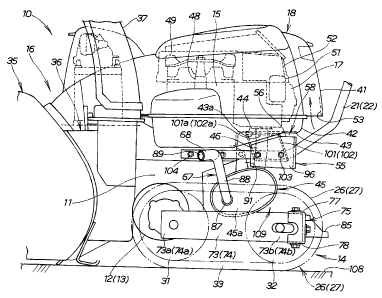
Referring now to the drawings and Fig. 1 in particular, there is shown a
self-propelled walk-behind crawler snowplow vehicle 10 according to an
embodiment of the present invention. The snowplow vehicle 10 generally
comprises a transmission case 11 as a body of the vehicle, left and right
electric
motors 12 and 13 mounted on left and right sides of a lower part of the
transmission case 11, a propelling apparatus 14 disposed on the lower part of
the
transmission case 11 and operatively connected to the electric motors 12, 13,
an
engine 15 mounted on an upper part of the transmission case 11, a snowplow
unit 16 disposed forwardly of the transmission case 11 and driven by the
engine
15, and left and right handlebars 21 and 22 extending backwardly and upwardly
from the upper part of the transmission case 11. A rear end portion of the
snowplow unit 16 and the engine 15 in its entirety are covered by a cover 18.
A
silencer or muffler 45 is disposed below the engine 15 and rearward of the
transmission case 11, the muffler 45 being connected to the engine 15 via an
exhaust pipe 46. The snowplow vehicle 10 also includes an operation control
board 23 mounted astride the handlebars 21, 22 at a position near handgrips
24,
that are formed at respective distal ends of the handlebars 21, 22. The
handgx~ips 24, 25 are adapted to be gripped by a human operator 113 (Fig. 8B)
20 walking behind the snowplow vehicle 10 in order to maneuver the snowplow
vehicle 10.
The propelling apparatus 14 includes a left traveling unit 26 disposed on
a lateral outer side of the left motor 12, namely on a left side of the lower
part of
the transmission case 11, and a night traveling unit 27 disposed on a lateral
25 outer side of the right motor 13, namely on a right side of the lower part
of the
transmission case 11. The left traveling unit 26 comprises a driving wheel 31
connected in driven relation to an output shaft of the left motor 12, an idler
CA 02477052 2004-08-11
wheel 32 disposed rearward of the driving wheel 31 for free rotation, and a
crawler belt 33 trained around the driving wheel 31 and the idler wheel 32.
The right traveling unit 27 has the same structure as the left traveling
unit 26 just descxzbed above. Accordingly, structural parts of the right
traveling unit 27 are designated by the same reference characters as those
used
in the left traveling unit 26, and further description thereof will be
omitted.
The snowplow unit 16 comprises an auger section 35, a rotary blower
section 36 and a shooter section 37. The rotary blower section 36 has a blower
housing 61 mounted to a front end portion of the transmission case 11, and a
blower 62 rotatably disposed in the blower housing 61. The blower 62 is
mounted on a drive shaft 63 for rotation therewith. The auger section 35 has
an auger housing 64 joined with a front end of the blower housing 61, and an
auger 65 rotatably disposed in the auger housing 64.
The cover 18 is composed of an upper cover member 41 configured to
cover or enclose the engine 15 from above, and a lower cover member 42
configured to cover a bottom surface of the engine 14. When assembled
together to form the cover 18, the upper and lower cover members 41, 42 fully
cover the engine 15. The engine 15 is a so-called "vertical" engine having a
crankshaft 48 disposed vertically and a cylinder disposed horizontally.
In operation, the left and right motors 12, 13 are driven to rotate the left
and right driW ng wheels 31 so that the left and right crawler belts 33 travel
around the driving and idler wheels 31 and 32 to thereby propel the snowplow
vehicle 10 in a desired direction. While the snowplow vehicle 10 is traveling
forward, motive power from the engine 15 is transmitted to the auger 65 and
the
blower 62 for driving them to perform a snowplow operation.
As shown in Fig. 2, the lower cover member 42 has a bottom wall 43
formed with an opening 44 for the passage therethrough of the exhaust pipe 46.
_g_
CA 02477052 2004-08-11
The exhaust pipe 46 extends from the engine 15 in a vertical downward
direction
through the opening 44 and is connected at a lower end thereof to a body of
the
muffler 45. Thus the muffler 45 is disposed below the engine 15 and located in
a space defied between the left and right traveling units 26, 27 at a rear
side of
the transmission case 11.
The engine 15 is provided with a carburetor 51 and an air cleaner 52
that are connected to a right side of the engine 15 (see also Fig. 3). The
engine
15, carburetor 51 and air cleaner 52 are covered by the cover 18 such that an
air
intake hole 53 is formed at a rear end portion of the upper cover member 41.
The air intake hole 53 opens downward. When the engine 15 is running, the
crankshaft 48 rotates a cooling fan 49 so that air outside the cover 18 is
drawn or
introduced from the air intake hole 53 into the cover 18. The outside air thus
introduced is guided by a rear end wall of the upper cover member 41 to flow
upward as indicated by the arrow and subsequently introduced into the air
cleaner 52 and the carburetor 51 in sequence.
The muffler 45 is disposed below and forward of the air intake hole 53.
Stated more specifically, the muffler 45 is disposed substantially beneath a
cylinder head 17 of the engine 15 (see also Fig. 3) that is located rearward
of the
crankshaft 48. The cylinder head 17 is disposed horizontally and oriented
backward of the snowplow vehicle 10. The muffler 45 is disposed horizontally
with its axis extending in a widthwise direction of the snowplow vehicle 10. A
partition wall 55 is disposed between the muffler 45 and the air intake hole
53 in
such a manner that a vertical space or gap 58 is formed between an upper edge
56 of the partition wall 55 and the bottom wall 43 of the lower cover member
42.
As shown in Fig. 3, the auger housing 64 is disposed forwardly of the
transmission case 11 (Fig. 1) and extending in the widthwise direction of the
snowplow vehicle 10, and the blower housing 61 is disposed between the auger
-9-
CA 02477052 2004-08-11
housing 64 and the transmission case 11. The engine 15 is mounted on the
transmission case 11 for driving the auger 65 and the blower 62 and includes
an
exhaust system having the muffler 45. The left and night handlebars 21, 22
extend from a rear part of the transmission case 11 in a backward direction of
the snowplow vehicle 10.
The muffler 45 has a tail pipe 67 extending from an end wall of the
muffler 45 in a widthwise direction of the snowplow vehicle 10. The tail pipe
67
has a discharge end portion 68 bent forwardly at angle ~ with respect to a
line
114 parallel to a longitudinal centerline of the snowplow vehicle 10. The bent
angle 8 of the discharge end portion 68 is determined such that a stream of
exhaust gases 71 (Figs. 7A and 7B) discharged from the tail pipe 67 does not
strike on or interfere with a left rear corner 66 of the auger housing 64.
If the stream of exhaust gases stxzkes on the auger housing 64, heat of
exhaust gases will melt down snow inside the auger housing 64. The molten
snow, i.e., water remaining inside the auger housing 64 may freeze up while
operation of the snowplow vehicle 10 is stopped. Icing thus occurring inside
the
auger housing 64 will hinder or sometimes stop smooth start of the auger
section
35. In case of the snowplow vehicle 10 of the invention, such icing problem
does
not occur because a stream of exhaust gases discharged from the forwardly bent
discharge end portion 68 of the tail pipe 67 does not inteWere with the auger
housing 64. The phantom line 114 shown in Fig. 3 indicates a snow wall formed
by the auger section 35 during snowplow operation of the snowplow vehicle 10.
As shown in Fig. 4, the left traveling unit 26 includes a left side frame
73 disposed horizontally and extending in a longitudinal direction of the
snowplow vehicle. The left driving wheel 32 (Fig. 2) is rotatably mounted on a
front end portion 73a (Fig. 2) of the left side frame 73, and the left idler
wheel 32
is rotatably mounted on a rear end portion 73b of the left side frame 73.
-10-
CA 02477052 2004-08-11
Similarly, the right traveling unit 27 includes a right side frame 74
extending
parallel to the left side frame 73. The right dxzving wheel 31 (Fig. 2) is
rotatably mounted on a front end portion 74a (Fig. 2) of the right side frame
74,
and the right idler wheel 32 is rotatably mounted on a rear end portion 74b of
the right side frame 74. Rear ends of the left and right side frames 73, 74
are
connected together by a cross member 75. The muffler 45 is disposed between
the left and night side frames 73, 74 (namely, between the left and right
traveling units 26, 27), and the cross member 75 is disposed behind or
backward
of the muffler 45.
The cross member 75 has a U-shaped cross section includes a vertical
wall 76 and upper and lower horizontal walls 77 and 78 (Fig. 2) extending
forwardly from upper and lower edges of the vertical wall 76. Opposite ends of
the U-shaped cross member 75 are substantially closed by left and right end
walls 81, 82 extending forwardly from left and night end edges of the vertical
wall 76. The cross member 75 has a box-like configuration open forward.
For assembly, the cross member 75 of forwardly open box-like
configuration is fitted over the rear end portions 73b, 74b of the left and
right
side frames 73, 74, and left and xzght end portions 75a, 75b of the cross
member
75 and the rear end portions 73b, 74b of the left and right side frames 73, 74
are
connected together by a plurality of screws 83.
The cross member 75 has a bracket 85 at a central portion thereof. The
bracket 85 is connected to a lower end 86a of a cylinder actuator 86 (Fig. 1).
The cylinder actuator 86 forms a part of a lift mechanism provided to move the
transmission case 11 (Fig. 2) to undergo vertical swinging movement about axes
of the left and might driving wheels 31.
As previously discussed, the muffler 45 is disposed between the left and
right side frames 73, 74 (i.e., between the left and right traveling units 26,
27)
-11-
CA 02477052 2004-08-11
with the cross member 75 disposed behind the muffler 45. With this
arrangement, left and right end walls 45a, 45b of the muffler 45 are protected
by
the left and xzght traveling units 26, 27, respectively, and a rear part 45c
of the
muffler 45 is protected by the cross member 75. The muffler 45 thus protected
is substantially free from damage. By thus using the traveling units 26, 27 as
a
protection means, the muffler 45 does not require a separate protection
member.
The muffler 45 is in the form of an elliptical cylinder disposed
horizontally with its axis extending transversely of the transmission case 11
(Fig.
2). The exhaust pipe 46 extends upward fiom the rear part 45c of the muffler
45 and has a flange 47 at an upper end thereof. The flange 47 is connected to
an exhaust manifold of the engine 15 (Fig. 2). The tail pipe 67 extends from
the
left end wall 45a in a lateral outward direction of the snowplow vehicle. The
tail pipe 67 has a base portion (proximal end portion) 87 connected to the
left
end wall 45a of the muffler 45, a central portion 88 extending upward from the
base portion 87 to the extent that an upper end 88a of the central portion 88
is
disposed above the left crawler belt 33 (Figs. 2 and 3), and the discharge end
portion 68 extending from the upper end 88a of the central portion 88. The
discharge end portion 68 is also disposed above the left crawler belt 33
(Figs. 2
and 3). As shown in Fig. 3, the discharge portion 68 has a bent shape
extending
from the upper end 88a of the central portion 88 first in a lateral outward
direction and subsequently in a diagonally forward direction, which is
inclined
at an angle 8 to the longitudinal centerline of the snowplow vehicle 10.
As shown in Fig. 2, the muffler 45 is attached by a bracket 91 to a rear
end of the transmission case 11 (Fig. 2). The muffler 45 is disposed below the
cylinder head 17 of the engine 15 and located between the left and right
traveling units 26, 2?. More specifically, the snowplow vehicle 10 has a
so-called "dead space" 109 defied between the cylinder head 17 of the engine
15,
- 12-
CA 02477052 2004-08-11
the rear end of the transmission case 11, the left and right traveling units
26, 27
and a ground surface 108. The muffler 45 is disposed in the dead space 109 for
a reason described later.
The partition wall 55 is disposed upwardly and rearward of the muffler
45. As shown in Fig. 4, the partition wall 55 is formed from a single plate
bent
into a U-shaped configuration for a reason described later. The partition wall
55 has an end plate 95 extending parallel to the rear part 45c of the muffler
45,
and left and right side plates 96, 97 extending forward from left and right
end
edges of the end plate 95. The end plate 95 has a pair of U-shaped cutout
recesses 98, 99 formed at an upper edge thereof at positions located adjacent
the
left and right ends of the end plate 95 for the passage therethrough of the
left
and right handlebars 21, 22, respectively. The left handlebar 21 has a portion
extending along an inner surface of the left side plate 96 with a left support
bracket 101 disposed therebetween, and the right handlebar 22 has a portion
extending along an inner surface of the right side plate 97 with a right
support
bracket 102 disposed therebetween. The left handlebar 21, the left support
bracket 101 and the left side plate 96 of the partition plate 55 are connected
together by a pair of bolt-and-nut fasteners 103. Similarly, the right
handlebar
22, the right support bracket 102 and the right side plate 97 of the partition
wall
55 are connected together by a pair of bolt-and-nut fasteners 103 (only one
being
shown in Fig. 4). The partition wall 55 is thus attached to the left and right
handlebars 21, 22. As shown in Fig. 2, the left and right handlebars 21, 22
have respective forward end portions secured by bolts 104 to left and might
side
walls of the transmission case 11.
The left and night support brackets 101, 102 have mounting flanges
lOla, 102a (Fig. 4) at upper ends thereof. The mounting flanges lOla, 102a are
connected to a hozzzontally extending rear part 43a of the bottom wall 43 of
the
-13-
CA 02477052 2004-08-11
lower cover member 42, as shown in Fig. 2. The lower cover member 42 is thus
supported at the rear part 43a of the bottom wall 43 thereof by means of the
left
and right support brackets 101, 102.
Operation of the snowplow vehicle 10 of the foregoing construction will
be described with reference to Figs. 5 to 7. Fig. 5 diagrammatically shows the
manner of flow or transmission of radiant heat from the muffler 45 and the
manner of flow of air introduced in the cover 18. When the engine 15 is
running, the crankshaft 48 rotates the cooling fan 49 so that air outside the
snowplow vehicle 10 is drawn or introduced from the air intake hole 53 into
the
cover 18, as indicated by the arrow A. The air is then drawn toward the
cooling
fan 49 while being guided by an inner surface of the cover 18, as indicated by
the
arrows B and C. A part of the air is introduced into the air cleaner 52 and
thence into the carburetor 51, as indicated by the arrow D. From the
carburetor 51 the air is supplied into an intake manifold of the engine 15.
The remaining part of the air is forced against the engine 15 to cool the
engine 15, as indicated by the arrow E. After cooling the engine 15, the air
is
discharged from the opening 44 of the lower cover member 42 into a space
extending forwardly of the partition wall 55, as indicated by the arrow F In
this instance, the partition wall 55 guides the air in a downward direction,
as
indicated by the arrow G, so that the air flows downward along the exhaust
pipe
46, thereby cooling the exhaust pipe 46.
By virtue of the partition wall 55 disposed vertically between the air
intake hole 53 and the muffler 45, the air discharged from the cover 16 is
guided
downward toward the muffler 45, as indicated by the arrow G, and is prevented
from being introduced again from the air intake hole 53 into the cover 18. By
thus blocking reentry of the air into the cover 18, the engine 15 received
inside
the cover 18 can be cooled with high efficiencies. The partition wall 55
disposed
- 14-
CA 02477052 2004-08-11
between the muffler 45 and the air intake hole 53 is effective to separate the
air
intake hole 53 from the muffler 45 to thereby block unlimited direct
transmission of radiant heat from the muffler 45 to the air intake hole 53.
When outside air is introduced from the air intake hole 53 into the cover
18 with snow flakes or powders entrained in the air, the snow powders may
cause freezing or icing inside the cover 18. To avoid this problem, the
vertical
space or gap 58 is provided between an upper end of the partition wall 55 and
the bottom wall 43 of the cover 18 so that a necessary amount of radiant heat
is
allowed to transmit from the muffler 45 to the air intake hole 53. The term
"necessary amount of radiant heat" means an amount of radiant heat which is
sufficient to melt down and vaporize snow 106 adhering to a neighboring part
of
the air intake hole 53 but does not affect cooling of the engine 15 when
introduced from the air intake hole 53 into the cover 18. By thus introducing
the necessary amount of radiant heat from the muffler 45 into the air intake
hole 53, the snow 106 adhering to the neighboring part of the air intake hole
53
will melt down and become vapor. Furthermore, since the partition wall 55 is
heated by radiant heat from the muffler 45, deposited snow 106 on the
partition
wall 45 can be also melting down and vaporized. This ensures that the air
introduced from the air intake hole 53 into the cover 18 is free from snow
flakes
or powders entrained therein and the freezing or icing problem does not occur
inside the cover 18.
As previously described, the muffler 45 is disposed below the engine 15
and located between the left and right traveling units 26, 27. Stated more
specifically, the engine 15 (more particularly the cylinder head 17 of the
engine
15) and the left and right traveling units 26, 27 define the space 109 open
downward, and the muffler 45 is disposed in the space 109. This arrangement
allows the muffler 45 to be located near the ground surface 108. The muffler
45
-15-
CA 02477052 2004-08-11
thus arranged is kept sufficiently far from the head of the operator walking
behind the snowplow vehicle 10 and does not obstruct forward field of vision
of
the operator when looking ahead of the auger section 35 (Fig. 2). Furthermore,
the ground 108, as indicated by the arrow H in Fig. 5, absorbs exhaust sound
emitted from the muffler 45. Thus, substantive reduction of exhaust sound can
be achieved. Additionally, the muffler 45 is cooled with high efficiencies
because radiant heat emitted from the muffler 45 in a downward direction, as
indicated by the arrow I in Fig. 5, can be taken up or absorbed by the ground
108
of low temperature or snow deposited on the ground surface 108.
In the illustrated embodiment, the partition wall 55 has a U-shaped
configuration, as shown in Fig. 4, the reason for which will become apparent
from a description given below with reference to Figs. 6A and 6B. Fig. 6A
shows a partition wall 200 disposed between the muffler 45 and the air intake
hole 53 for comparative purposes. The partition wall 200 is formed from a
rectilinearly extending elongate plate having a larger length than the muffler
45
and disposed vertically with left and right end edges 202, 203 located outward
of
left and right end walls (not designated) of the muffler 45. With this
arrangement, a part of the air, which has been used for cooling the engine 15
(Fig. 5), is discharged downward from the opening 44 of the cover 18 (Fig. 5).
In
this instance, the rectilinear partition wall 200 allows the discharged air to
flow
around the left and night end edges 202, 203 of the partition wall 200, as
indicated by the arrows J and K, thus moving from one side of the partition
wall
200 facing the muffler 45 to the other side of the partition wall 400 facing
the air
intake hole 53. The discharged air can be subsequently drawn from the air
intake hole 53 into the cover 18 (Fig. 5). Since the discharge air is higher
in
temperature than the flesh outside air, introduction of the discharged air
will
lower the cooling efficiency of the engine 15.
-16-
CA 02477052 2004-08-11
Fig. 6B diagrammatically shows an arrangement in which the partition
wall 55 of U-shaped configuration is disposed between the muffler 45 and the
air
intake hole 53 so that the left and right side plates 96, 97 projecting
forward
from left and right end edges of the end plate 95 disposed backward of the
muffler 45. With this arrangement, a part of the air, which has been used for
cooling the engine 15 (Fig. 5), is discharged from the opening 44 in a
downward
direction. In this instance, since the U-shaped partition wall 55 open
forward,
the discharged air is guided by the end plate 95 and the left and right side
plates
96, 97 to flow in a forward direction (i.e., a direction away from the air
intake
hole 53), as indicated by the arrows K and L. Thus, the air discharged from
the
cover 18 (Fig. 5) is prevented from being introduced from the air intake hole
53
into the cover 18. This insures high engine cooling efficiencies.
Figs. 7A and 7B diagrammatical illustrate the manner in which exhaust
gases are discharged from the tail pipe 67 of the present invention when the
snowplow vehicle 10 is traveling alongside a snow wall 114, and Figs. 8A and
8B
are views similar to Figs. 7A and 7B, respectively, but shows a problem caused
by exhaust gases discharged from a tail pipe 212 of a snowplow vehicle 210
according to a comparative example.
As shown in Figs. 7A and 7B, the tail pipe 67 extending from the left end
wall of the muffler 45 has a discharge end portion 68 bent forward at an angle
B (Fig. 7A) to the longitudinal centerline (not shown but extending
substantially parallel to the snow wall 114) so that a stream of exhaust gases
71
discharged from the tail pipe 67 does not strike on or interfere with the left
rear
corner 66 of the auger housing 64. By thus orienting the discharge end portion
68 of the tail pipe 67, it is possible to prevent the exhaust gas from being
reflected from the auger housing 61 in a direction toward the operator 113
(Fig.
7B), to lower the level of exhaust sound emitted from an exhaust system
- 17-
CA 02477052 2004-08-11
including the muffler 45 and the tail pipe 67, to prevent the exhaust gas from
being reflected from the snow wall 114 in a direction toward the operator 113,
and allow the exhaust gases 71 to create snow flakes 116 splashed from the
snow
wall 14 in a forward direction to thereby protect the operator 113 from a
shower
of snow flakes 116.
As shown in Figs. 8A and 8B, the tail pipe 212 according to the
comparative example has a discharge end portion 213 directed in a lateral
outward direction at right angles to a longitudinal center line (not shown but
extending substantially parallel to a snow wall 114). With the discharge end
portion 213 thus oizented, a stream of exhaust gases 214 emitted from the tail
pipe discharge end portion 213 is partly reflected from the snow wall 114 in a
backward direction toward the operator 113, as indicated by the arrow M. The
thus reflected stream of exhaust gases 214 transfers a high level of exhaust
sound directly to the operator 113 and can cause headaches and impaired
vision.
Furthermore, the stream of exhaust gases 214 may create snow flakes splashed
from the snow wall 114 in a backward direction of the snowplow vehicle 210.
As the snowplow vehicle 210 moves forward, the snow flakes 116 flow backward
and eventually strike as a shower onto a body of the operator 113, causing
discomfort to the operator 113.
As thus far explained, the invention is practiced or embodied in a
self-propelled walk-behind snowplow vehicle 10 of the type having a snowplow
unit 16 including an auger section 35 and a blower section 36. This invention
may be practiced or embodied a snowplow vehicle having a different type of
snowplow unit. Furthermore, while in the illustrated embodiment, the partition
wall 55 is disposed vertically, a backwardly tilted partition wall may
alternatively used. Additionally, the partition wall 55 of U-shaped
configuration
may be replaced with a partition wall having a generally C-shaped
configuration.
- 18-
CA 02477052 2004-08-11
In the illustrated embodiment, the partition wall 55 and the bottom wall 43 of
the lower cover member 42 are vertically separated by the space 58. In a
modified embodiment, the partition wall 55 may be held in contact with the
bottom wall 43 of the lower cover member 42. Furthermore, the partition wall
55 in the illustrated embodiment is bolted to the left and might handlebars
21, 22.
The way of attachment of the partition wall 55 should by no means be limited
to
one shown in the illustrated embodiment but may include another way of
attachment wherein the partition wall 55 is attached to the lower cover member
42.
Furthermore, the shape and configuration of the muffler 45 is not
limited to an elliptical cylinder as in the illustrated embodiment but may be
selected at option. Similarly, the tail pipe 45 has no limitation in shape and
configuration thereof except for a particular orientation of the discharge end
portion 68. Additionally, the shape and configuration of the cross member 75
is
not limited to one shown in Fig. 4 but may include any other variations
provided
that a cross member as assembled with the left and right side frames 73, 74,
can
effectively protect a rear part of the muffler 45 from damage.
- 19-